D Series

Fahrenheat D Series, F2544 Installation guide

  • Hello! I am an AI chatbot trained to assist you with the Fahrenheat D Series Installation guide. I’ve already reviewed the document and can help you find the information you need or explain it in simple terms. Just ask your questions, and providing more details will help me assist you more effectively!
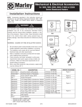
Wiring Instructions for Marley 2500 Series
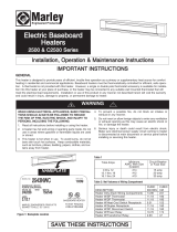
Electric Baseboard Heaters
General Safety Information:
These instructions are intended to supplement the installation instruction manuals provided with your
heater and thermostat. Please refer to these manuals for additional instructions and safety warnings.
If you continue to have questions regarding the installation procedure you may call our Technical
Services Hotline at 1-800-642-HEAT for assistance.
STEP 1
The 2500 Series Baseboard can be
wired from either end. Remove the
screw in junction box cover to reveal
wire compartment.
STEP 2
Bare copper ground wire.
Locate the two wires joined with an
orange wire nut.
STEP 3
Remove wire nut by turning it count-
er clockwise.
STEP 4
Separate the two wires by pulling
them apart.
STEP 5
Bring the power supply wires into
the junction box. A built-in clamp is
provided or you may remove one of
the knockouts. If a knockout is used,
an appropriate wire clamp must be
used.
STEP 6
Attach the bare copper ground wire
from the power supply to the ground
wire in the junction box with a wire
nut.
Note: Steps 7-9 are for REMOTE
MOUNTED THERMOSTATS ONL
Y
.
If you are using the unit mounted
thermostat, skip to step 10.
STEP 7
Attach the white wire from the power
supply to one of the wires that you
separated in step 4. Connect these
together with a wire nut.
STEP 8
Attach the black wire from the power
supply to the other wire separated in
step 4 using a wire nut.
STEP 9
Completed unit.
After all connections are completed,
double-check each to verify it is tight
and secure. Carefully fold wiring into
junction box and replace cover.
Note: Steps 10-15 are for INTER-
NAL BUILT-IN THERMOSTATS
ONL
Y. Following example uses dou-
ble-pole thermostat.
STEP 10
Locate the red wire(s) on the ther-
mostat. These are the L1 and L2
and attach to the power supply. The
black wire(s) are the load side and
attach to the heater.
STEP 11
Attach one red wire from the ther-
mostat to the white wire from the
power supply with a wire nut.
From Thermostat
From Power Supply
STEP 12
Attach the other red wire from the
thermostat to the black wire from the
power supply with a wire nut.
STEP 13
Attach one black wire from the ther-
mostat to one wire in the heater
separated in step 4 using a wire nut.
From Thermostat
From Thermostat
From Power Supply
From Heater (see step 4)
STEP 14
Attach the other black wire from the
thermostat to the other heater wire
separated in step 4.
From Thermostat
From Heater (see step 4)
STEP 15
Complete unit with built-in thermo-
stat.
Check all wiring and connections
before applying power to the heater.
Note: If wiring multiple units to one
thermostat make sure the amp load
does not exceed the thermostat rat-
ing and wire size. Make connections
for next heater at the same location
the two black wires from the thermo-
stat attached to the two wires in the
heater (see below).
When second heater is to be controlled
by thermostat in first heater.
1. Bring cable from second heater into
wiring compartment through built-in
cable clamp or knockout using cable
clamp.
2. Connect BLACK wire from second
heater at wire nut D.
3. Connect WHITE wire from second
heater at wire nut E.
4. Connect BARE (or GREEN) ground
wire from second heater at wire nut C.
D
C
E
Instructions for wiring multiple heaters to a single thermostat
TO SECOND
HEATER
TO HEATING
ELEMENT
LIMIT
B
A
R
E
B
L
A
C
K
B
L
A
C
K
W
H
I
T
E
B
A
R
E
SUPPLY AT LEFT END
TO SECOND
HEATER
TO HEATING
ELEMENT
B
L
A
C
K
W
H
I
T
E
B
A
R
E
B
L
A
C
K
W
H
I
T
E
B
A
R
E
POWER
SUPPLY
POWER
SUPPLY
SUPPLY AT RIGHT END
W
H
I
T
E
/