Page is loading ...

GENTLE FLUID HEAT
FOR THE PEOPLE YOU LOVE MOST
http://cadetheat.com/install/softheat
For how-to videos or more information, please visit:
ESPAÑOL ver la guía del propietario en cadetheat.com/espanol/softheat
cadetheat.com
855.CADET.US
Vancouver, Washington
tested to UL standards
OWNER’S GUIDE
SOFTHEAT

SAVE THESE INSTRUCTIONS
IMPORTANT INSTRUCTIONS
2
KNOW YOUR VOLTAGE!
TOOLS REQUIRED
1. Read all instructions before
installing or using this heater.
2. A heater has hot and arcing or
sparking parts inside. Do not use
it in areas where gasoline, paint,
or ammable vapors or liquids are
used or stored.
3. This heater is hot when in use. To
avoid burns, do not let bare skin
touch hot surfaces. Keep combus-
tible materials, such as furniture,
pillows, bedding, papers, clothes,
and curtains away from heater.
4. To prevent a possible re, do
not block air intakes or exhaust
in any manner. Do not use on
soft surfaces, like a bed, where
openings may become blocked.
5. Do not insert or allow foreign
objects to enter any ventilation
or exhaust opening as this may
cause an electric shock or re, or
damage the heater.
6. Use this heater only as described
in this manual. Any other use
not recommended by the
manufacturer may cause re,
electric shock, or injury to persons.
7. This heater must be installed in a
xed, permanent location.
8. CAUTION – High temperature.
Keep electrical cords, drapes,
and other furnishings away from
heater.
9. Extreme caution is necessary
when any heater is used by or near
children or invalids and whenever
the heater is left operating and
unattended.
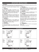
When using electrical appliances, basic precautions should always be
followed to reduce the risk of re, electric shock, and injury to persons,
including the following:
120 volt
single pole breaker
240 volt
double pole breaker
• A 120 volt heater will fail if connected to a 240 volt electrical supply! Connecting a 240
volt heater to a 120 volt electrical supply will only give you one quarter of the heat
output.
Tape Measure
Straight and Phillips
Screwdrivers1½" Wood ScrewsWire Strippers Wire Connectors
½" Cable Clamp
Connector
Volt Meter
Drill and Drill Bits
Stud Finder
A multi-purpose tool or something to cut your existing base trim or molding
®
®
®
®
®
®
®
Hammer
®
®
®
®
If you are uncomfortable working with electricity, running electrical supply wire or install-
ing a circuit breaker, please consult a licensed electrician.
Unanswered questions? Call our technical support team in Vancouver, Washington at
855.CADET.US (855.223.3887) or 360.693.2505.
• Make sure the heater is the same voltage as the electrical supply wires you’re using. The
wire size must be correct for the voltage, the heater wattage and the circuit breaker.
Level
®

INSTALLATION INSTRUCTIONS
3
STEP 1
Locate or route electrical supply wires
1. All electrical work and materials
must comply with the National
Electric Code (NEC), the Occu-
pational Safety and Health Act
(OSHA), and all state and local
codes.
2. Use copper conductors only.
3. Do not install below an electrical
receptacle.
4. Do not install the heater
against combustible low-density
cellulose berboard.
5. Heater must be level.
6. CAUTION – High temperature.
Keep electrical cords, drapes,
and other furnishings away from
heater.
7. To reduce the risk of re, do not
store or use gasoline or other
ammable vapors and liquids in
the vicinity of the heater.
8. Maintain at least 12 inches (30.5
cm) minimum clearance from all
objects above and in front of base-
board, and 6 inches (15.2 cm) mini-
mum on both sides.
1. Turn o the electrical power supply. Locate
wall studs and electrical supply wires.
Remove front cover by lifting up from the
bottom, and then outward.
2. Unscrew and remove wiring compartment
cover from the end you’re wiring. No need
to remove the cover on the other side.
• For best results, install your SoftHeat baseboard heater under a window and use an electronic wall
thermostat.
• Install only in a horizontal position, not in a vertical position.
• Remove any oor base trim or molding so the heater will set ush against the wall. It can sit directly
on any oor surface, including carpet.
• If you’re wiring a WALL thermostat, route the electrical supply wire from the circuit breaker to the
wall thermostat, and then to the baseboard. If you’re wiring a BUILT-IN model EBKN thermostat,
route the electrical supply wire from the circuit breaker directly to the baseboard.
• SoftHeat baseboard wire connections can be made on either end of the baseboard heater.
NOTE: All baseboard heaters require a thermostat (sold separately)
PARTS OF YOUR HEATER
Figure 1
electrical
supply wire
wall studs
overvoltage safety shuto (120 volt models only)
high-temperature safety shuto
element
grounding screw
wiring
compartment
cover
The volume of the left end SoftHeat wiring compartment is 40 cubic inches (655.5 cubic centimeters)
and the volume of the right end wiring compartment is 33 cubic inches (540.8 cubic centimeters).

INSTALLATION INSTRUCTIONS
4
5. Connect the grounding lead to the green grounding screw on the side you’re wiring.
• KNOW YOUR VOLTAGE and CHECK YOUR BREAKER!
• All baseboards require two supply wires and a grounding lead. For 240 volts, both supply wires
(black and white) are hot. For 120 volts, one supply wire is hot (black) and one is neutral (white). For
208 volts, applications vary and both supply wires (black and white) can be hot or you may have one
hot and one neutral.
STEP 2
Wire connection
If you’re wiring a WALL thermostat for your heater, follow the instructions below. Your electrical supply
wires should be routed from the circuit breaker to the wall thermostat, and then to the heater.
grounding
screw
3. Remove one of the knockouts in the wiring com-
partment. We recommend using the rear knockout.
If you use the bottom one, you must protect the
wire with electrical tubing and add a conduit con-
nector (not included) at the oor.
120 VOLT - LEFT END240/208 VOLT - LEFT END
1. When wiring on either end, connect one
supply wire to one of the heater wires with a
wire connector (not included).
A. For 240 volts, or 208 volts with two hot
supply wires, both ends connect the same,
it doesn’t matter which heater wire (Figure 2
or Figure 6).
B. For 120 volts, connect the neutral (white)
supply wire to the white heater wire on the
left end (Figure 3). On the right end, connect
the wire labeled NEUTRAL to the white
supply wire (Figure 5).
Figure 2 Figure 3
4. Install a cable clamp connector (not
included). Pull supply wires through the
cable clamp connector leaving 6-inch (15.2
cm) wire leads.
If you’re wiring a BUILT-IN model EBKN thermostat for your heater, go to those instructions now
(included with your thermostat) and follow that installation. When complete, proceed to Mount heater
to wall on page 5.
knockout
cable clamp
connector (view
from back)
grounding
lead
new
connection
new connection
new
connection
do not disconnect
Supply
(white)
wire
wrapped
with
black
tape to
identify
it as
hot, not
neutral!
do not disconnect
new
connection
do not disconnect
IMPORTANT!
FOR LEFT END WIRING, cut only one factory connection. For 240 volts, you can cut any
connection. For 120 volts, cut the one with the white wire. For 208 volts, cut the one with the
orange wire.
FOR RIGHT END WIRING, cut the one factory connection.
After cutting the factory connection on the end you’re wiring, you will have two wires to connect to
the power supply.

INSTALLATION INSTRUCTIONS
5
STEP 3
Mount heater to wall
MULTIPLE HEATERS WITH ONE THERMOSTAT (240 or 208 volt only)
More than one heater can be wired in parallel on the same circuit breaker (be sure to check national
and local codes for safety requirements). Additional electrical supply wire and cable clamp connectors
are required, and you’ll need to use a wall thermostat (See Figure 8 on page 6). When wiring multiple
heaters to one thermostat, the heaters must be in the same room.
The maximum amperage load you can put on one circuit breaker is limited to either 80% of the circuit
breaker capacity, or the maximum amperage rating of the thermostat, whichever is lower.
Figure 7
1. Drill holes in shaded areas only and secure to two or three wall studs with wood screws (not
included). IMPORTANT: make sure your heater is level before tightening screws down all the way.
2. Attach the heater front cover.
3. Turn power back on at the main disconnect panel.
4. Proceed to OPERATING INSTRUCTIONS.
Drill in this area only
Drill in this area only
All SoftHeat baseboards come with a built-in high-temperature safety shuto that stops electricity
owing to the heater if it gets too hot inside. This automatically resets after cooling.
In addition to the standard safety feature, 120 volt SoftHeat baseboards have a unique built-in feature
that stops electricity owing to your heater if it’s connected to the wrong voltage.
208 VOLT - LEFT END
ALL VOLTAGES - RIGHT END
NEUTRAL
Figure 4
Figure 5
120 or 208 volt
One hot, one neutral
new connection
Supply
(white) wire
wrapped
with black
tape to iden-
tify it as hot,
not neutral
in 240 or
208 volt
application!
do not disconnect
new
Figure 6
240 or 208 volt
Two hot
C. For 208 volts, connect the neutral (white)
supply wire to the orange heater wire on
the left end (Figure 4). On the right end with
a neutral supply, connect the wire labeled
NEUTRAL to the white supply wire (Figure
5).
2. Connect the remaining supply wire to the
remaining heater wire with a wire connector.
3. Tuck all wires back into the wiring compart-
ment, and make sure the connections are
tight.
4. Screw the wiring compartment cover back on.
new
connection
new
connection
new
connection
new
connection
connection
Please verify installation
After installation, operate your SoftHeat baseboard for at least 30 minutes with the thermostat
set to its maximum temperature. If your room doesn’t get warmer, please contact Cadet directly,
as your electrical supply voltage may not match the heater voltage.
855.CADET.US (855.223.3887) or 360.693.2505
live chat: cadetheat.com/customer-service
blog: cadetheat.com/120v-softheat

INSTALLATION INSTRUCTIONS
6
L2
Ground
L1
Ground
L1
L2
Ground
L1
L2
Neutral
Ground
L1
Ground
Neutral
L1
Figure 9
Figure 11
Figure 12
Double pole
wall thermostat
left end wiring
120 volt left
end wiring
240/208 volt
left end wiring
INTERNAL HEATER WIRING DIAGRAMS
Connecting
multiple units
240 or 208 volt
models only
Multiple heaters must join
at wall thermostat, not in
heater wiring compartment
1. A separate set of electrical supply wire must be run from the wall thermostat to each baseboard.
2. All the 3-wire connections must be made in the electrical junction box of the wall thermostat (See
Figures 8 and 12)! They cannot be made in either of the wiring compartments of the heaters. An
extra deep electrical junction box is recommended so you’ll have enough room for all the wires.
Tuck all wires back into the junction box and make sure the connections are tight.
3. In the wiring compartment of each heater, connect one supply wire to one of the heater wires with
a wire connector (not included), it doesn’t matter which one (See Figure 2 or 4).
4. Connect the remaining supply wire to the remaining heater wire with a wire connector (not
included) (See Figure 2 or 4).
5. Tuck all the wires back into the individual wiring compartments, and make sure the connections
are tight.
6. Screw the wiring compartment covers back on. Proceed to STEP 3 on page 5.
from power
supply
double
pole wall
thermostat
(sold
separately)
Figure 8
ground
wire
connection
connections
with power
supply (line)
connections
with heaters
(load)
to
heater
#1
to
heater
#2
If both supply wires
are hot, wrap (white)
supply wires with
black tape to identify
them as hot, not
neutral!
L2/Neutral
Ground
L1
Ground
L2/Neutral
L1
Figure 10
208 volt left
end wiring
L2
Ground
L1
Ground
L1
L2
Neutral
Ground
L1
Ground
Neutral
L1
L2/Neutral
Ground
L1
Ground
L2/Neutral
L1
120 volt right
end wiring
240/208 volt
right end
wiring
208 volt right
end wiring

Reduce-Reuse-Recycle
This product is made primarily of recyclable materials. You can reduce your carbon footprint by recycling
this product at the end of its useful life. Contact your local recycling support center for further recycling
instructions.
WARRANTY
For more eective and safer operation and to
prolong the life of the heater, read the Owner’s
Guide and follow the instructions. Failure to prop-
erly maintain the heater will void any warranty and
may cause the heater to function improperly.
LIMITED SEVEN YEAR WARRANTY: Cadet will
repair or replace any Cadet SoftHeat (EBHN)
heater found to be defective within seven years
after the date of purchase.
These warranties do not apply:
1. Damage occurs to the product through improper
installation or incorrect supply voltage;
2. Damage occurs to the product through
improper maintenance, misuse, abuse, accident,
or alteration;
3. The use of unauthorized accessories or
unauthorized components constitutes an
alteration and voids all warranties. Refer to Cadet
website or call customer service at 855.223.3887
or 360.693.2505 for list of authorized accessories
and components.
4. Cadet’s warranty is limited to repair or
replacement.
5. In the event Cadet elects to replace any part
of your Cadet product, the replacement parts are
subject to the same warranties as the product. The
installation of replacement parts does not modify
or extend the underlying warranties. Replacement
or repair of any Cadet product or part does not
create any new warranties.
If you believe your Cadet product is defective,
please contact Cadet during the warranty period,
for instructions on how to have the repair or
replacement processed.
Parts and Service
Visit cadetheat.com/parts-service for information
on where to obtain parts and service.
How to operate your heater
The room temperature is controlled by a thermostat located either on the wall, or on the heater.
Once installation is complete and power has been restored, follow the steps below for your
thermostat.
If you have a wall or built-in thermostat with a knob:
1. Turn the thermostat knob all the way to the right.
2. When the room reaches your comfort level, turn the knob to the left, just until it clicks and the
heater turns o. The heater will automatically keep the room temperature around this setting.
3. To reduce the room temperature, turn the knob to the left. To increase the room temperature,
turn the knob to the right.
If you have an electronic thermostat, follow the instructions in the programming and operating guide
included with your thermostat.
OPERATING INSTRUCTIONS
To register your product, visit cadetheat.com/product-registration
1. Make sure all wires are properly
connected and your heater is
installed before you turn it on.
2. Do not tamper with the high-
temperature safety shuto.
7
The SoftHeat uid is a non-toxic mineral oil. No special rst aid measures are needed if the uid is
swallowed, inhaled, or if it gets on your skin or in eyes; simply rinse or wash with soap and water.
The uid does not freeze.
If the uid leaks, stop using the heater. Cleanup is the same as it is for used oil. Wipe up any leaking
uid with a rag or paper towel. Dispose of uid at a recycling center that accepts used oil. Wash
hands with soap and water.
For more information you can view the Safety Data Sheet here: cadetheat.com/softheat/sds
PLEASE NOTE: On initial start-up, the heater may cause an odor due to the manufacturing
process. It typically goes away within several hours.

MAINTAINING YOUR HEATER
Rev 06/22/18 #706955
8
Symptom Problem Solution
TROUBLESHOOTING
Clean heater at least every 24 months or as required.
1. It is important that you verify power has been
turned o and the element is cool.
2. Wipe cover with damp cloth and dry.
3. Use the hose on your vacuum to clean the
heater. Do not touch the element.
4. Turn power back on at the main disconnect
panel.
More frequently asked questions on our website here: cadetheat.com/support/FAQ
Any service other than cleaning should be performed by an authorized
service representative.
©2018 Cadet Printed in USA
If you are uncomfortable working with electricity, running electrical supply
wire or installing a circuit breaker, please consult a licensed electrician.
Heater
doesn’t get
hot.
1. Circuit breaker is 120
volts and heater is 240 volts.
2. Multiple baseboards wired
in series.
1. Double check the voltage of the heater to make sure it
matches the voltage of the circuit. Replace heater with a model
that is 120 volts.
2. Wire baseboards in parallel (see MULTIPLE HEATERS WITH
ONE THERMOSTAT on page 5).
Heater
doesn’t
work at all.
1. Circuit breaker is faulty.
2. Supply connections are
loose.
1. Call a licensed electrician.
2. Turn o power at main disconnect panel. Inspect and/or
tighten all the wire connectors inside the heater and at any con-
nection points inside junction boxes or at the wall thermostat.
Heater is
making
noise.
1. Heater makes creaking or
popping noises.
2. Humming noise.
1. The heating element expands slightly when turned on. This
is normal.
2. Baseboard cabinet may need slight adjustment. Call Cadet
technical support team at 855.CADET.US (855.223.3887) or
360.693.2505.
Heater
smells after
installation
or not being
used.
1. Odor from element
manufacturing process.
2. Supply connections are
loose.
3. Dust or lint inside the
heater.
1. On initial start-up, the heater may cause an odor due to the
manufacturing process. It typically goes away within several
hours.
2. Turn o power at main disconnect panel. Inspect and/or tight-
en all the wire connectors inside the heater and at any connec-
tion points inside wiring compartments or at the wall thermostat.
3. Clean heater (see “MAINTAINING YOUR HEATER” above for
instructions).
Heats
briey then
stops.
1. Overvoltage safety shuto
has tripped on initial startup
or rst use (120 volt models
only).
2. High-temperature safety
shuto has tripped.
1. Heater is 120 volts and connected to 240 volts. Replace
heater with a model that is 240 volts. Call Cadet at 855.CADET.
US (855.223.3887) or 360.693.2505 for assistance.
2. Remove all obstructions. Do not block heater. Maintain 12
inches (30.5 cm) above and front. Keep heater free of lint and
dust.
Heater
doesn’t turn
o.
1. Thermostat is defective.
2. No thermostat hooked up
to control heater.
3. Incorrect heater wattage
for room size.
1. Replace thermostat.
2. A thermostat is required for all heaters. Purchase a built-in or
wall thermostat for your heater.
3. Install higher wattage model or additional heaters if circuit
allows.
Breaker
trips imme-
diately after
installing
heater.
1. A short circuit exists in
the electrical supply wires or
heater wiring.
2. Circuit is overloaded.
3. Circuit breaker is faulty.
1. An incorrect connection in the heater or electrical supply wires
may cause sparking or arcing. Inspect all heater and electrical
supply wiring insulation for damage or call an electrician.
2. Use a lower wattage heater, or reduce the number of heaters
on the circuit.
3. Call a licensed electrician.
Liquid found
in or around
heater.
1. Heat transfer uid drip-
ping from element.
1. Discontinue use. Replace the element or the heater
(elements are not repairable).
/