Page is loading ...

Revision Date: Mar. 01, 2005
Renesas Microcomputer Development Environment System
SuperH
Family / SH7700 Series
SH7710 E10A HS7710KCM02HE
Rev.1.00
SuperH
TM
Family E10A Emulator
Additional Document for User’s Manual
Specific Guide for the SH7710 E10A Emulator
REJ10B0186-0100


1. These materials are intended as a reference to assist our customers in the selection of the Renesas
Technology Corp. product best suited to the customer's application; they do not convey any license
under any intellectual property rights, or any other rights, belonging to Renesas Technology Corp. or
a third party.
2. Renesas Technology Corp. assumes no responsibility for any damage, or infringement of any third-
party's rights, originating in the use of any product data, diagrams, charts, programs, algorithms, or
circuit application examples contained in these materials.
3. All information contained in these materials, including product data, diagrams, charts, programs and
algorithms represents information on products at the time of publication of these materials, and are
subject to change by Renesas Technology Corp. without notice due to product improvements or
other reasons. It is therefore recommended that customers contact Renesas Technology Corp. or
an authorized Renesas Technology Corp. product distributor for the latest product information
before purchasing a product listed herein.
The information described here may contain technical inaccuracies or typographical errors.
Renesas Technology Corp. assumes no responsibility for any damage, liability, or other loss rising
from these inaccuracies or errors.
Please also pay attention to information published by Renesas Technology Corp. by various means,
including the Renesas Technology Corp. Semiconductor home page (http://www.renesas.com).
4. When using any or all of the information contained in these materials, including product data,
diagrams, charts, programs, and algorithms, please be sure to evaluate all information as a total
system before making a final decision on the applicability of the information and products. Renesas
Technology Corp. assumes no responsibility for any damage, liability or other loss resulting from the
information contained herein.
5. Renesas Technology Corp. semiconductors are not designed or manufactured for use in a device or
system that is used under circumstances in which human life is potentially at stake. Please contact
Renesas Technology Corp. or an authorized Renesas Technology Corp. product distributor when
considering the use of a product contained herein for any specific purposes, such as apparatus or
systems for transportation, vehicular, medical, aerospace, nuclear, or undersea repeater use.
6. The prior written approval of Renesas Technology Corp. is necessary to reprint or reproduce in
whole or in part these materials.
7. If these products or technologies are subject to the Japanese export control restrictions, they must
be exported under a license from the Japanese government and cannot be imported into a country
other than the approved destination.
Any diversion or reexport contrary to the export control laws and regulations of Japan and/or the
country of destination is prohibited.
8. Please contact Renesas Technology Corp. for further details on these materials or the products
contained therein.
1. Renesas Technology Corp. puts the maximum effort into making semiconductor products better and
more reliable, but there is always the possibility that trouble may occur with them. Trouble with
semiconductors may lead to personal injury, fire or property damage.
Remember to give due consideration to safety when making your circuit designs, with appropriate
measures such as (i) placement of substitutive, auxiliary circuits, (ii) use of nonflammable material or
(iii) prevention against any malfunction or mishap.
Keep safety first in your circuit designs!
Notes regarding these materials


i
Contents
Section 1 Connecting the Emulator with the User System................................1
1.1
Components of the Emulator ............................................................................................1
1.2
Connecting the Emulator with the User System ...............................................................3
1.3
Installing the H-UDI Port Connector on the User System................................................4
1.4
Pin Assignments of the H-UDI Port Connector................................................................4
1.5
Recommended Circuit between the H-UDI Port Connector and the MPU.......................7
1.5.1
Recommended Circuit (36-Pin Type)..................................................................7
1.5.2
Recommended Circuit (14-Pin Type)..................................................................10
Section 2 Specifications of the SH7710 E10A Emulator’s Software................13
2.1
Differences between the SH7710 and the Emulator .........................................................13
2.2
Specific Functions for the SH7710 E10A Emulator.........................................................17
2.2.1
Emulator Driver Selection ...................................................................................17
2.2.2
Break Condition Functions..................................................................................18
2.2.3
Trace Functions....................................................................................................19
2.2.4
Notes on Using the JTAG Clock (TCK) and AUD Clock (AUDCK) .................25
2.2.5
Notes on Setting the [Breakpoint] Dialog Box....................................................25
2.2.6
Notes on Setting the [Break Condition] Dialog Box and
the BREAKCONDITION_ SET Command ........................................................27
2.2.7
Note on Setting the UBC_MODE Command......................................................28
2.2.8
Performance Measurement Function ...................................................................28

ii

1
Section 1 Connecting the Emulator with the User System
1.1 Components of the Emulator
The SH7710 E10A emulator supports the SH7710. Table 1.1 lists the components of the
emulator.
Table 1.1 Components of the Emulator (HS7710KCM01H, HS7710KCM02H,
HS7710KCI01H, or HS7710KCI02H)
Classi-
fication
Component
Appearance
Quan-
tity
Remarks
Hard-
ware
Card emulator
Insert
PC Card Emulator
H-UDI Micro Computer
Development System
HITACHI
PC
Card
(PCMCIA)
or
(PCI)
1 HS7710KCM01H
(PCMCIA: 14-pin type):
Depth: 85.6 mm, Width: 54.0 mm,
Height: 5.0 mm, Mass: 27.0 g
HS7710KCM02H
(PCMCIA: 36-pin type):
Depth: 85.6 mm, Width: 54.0 mm,
Height: 5.0 mm, Mass: 28.0 g
HS7710KCI01H
(PCI: 14-pin type):
Depth: 144.0 mm, Width: 105.0
mm, Mass: 93.0 g
HS7710KCI02H
(PCI: 36-pin type):
Depth: 122.0 mm, Width: 96.0
mm, Mass: 90.0 g
User system interface
cable
1 HS7710KCM01H
(PCMCIA: 14-pin type):
Length: 80 cm, Mass: 45.0 g
HS7710KCM02H
(PCMCIA: 36-pin type):
Length: 30 cm, Mass: 55.0 g
HS7710KCI01H
(PCI: 14-pin type):
Length: 150 cm, Mass: 86.0 g
HS7710KCI02H
(PCI: 36-pin type):
Length: 80 cm, Mass: 69.0 g

2
Table 1.1 Components of the Emulator (HS7710KCM01H, HS7710KCM02H,
HS7710KCI01H, or HS7710KCI02H) (cont)
Classi-
fication
Component
Appearance
Quan-
tity
Remarks
Hard-
ware
Ferrite core
(connected with the
user interface cable)
1 Countermeasure for EMI*
(only for HS7710KCM02H and
HS7710KCI02H)
Soft-
ware
SH7710 E10A
emulator setup
program,
SuperH
TM
Family
E10A Emulator User’s
Manual, and
Specific Guide for the
SH7710 E10A
Emulator
1 HS7710KCM01SR,
HS0005KCM01HJ,
HS0005KCM01HE,
HS7710KCM02HJ, and
HS7710KCM02HE
(provided on a CD-R)
Note: The EMI is an abbreviation of the Electrical Magnetic Interference.
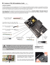
For EMI countermeasure, use the ferrite core by connecting the user interface cable.
When the user interface cable is connected with the emulator or user system, connect the ferrite
core in the user system as shown in figure 1.1.
User interface cable
Host computer (PC with PC card slot)
E10A emulator
PC card slot
Insert
PC Card Emulator
H-UDI Micro Computer
Development System
HITACHI
PC
Card
User system
User system connector
Ferrite core
Figure 1.1 Connecting Ferrite Core

3
1.2 Connecting the Emulator with the User System
To connect the E10A emulator (hereinafter referred to as the emulator), the H-UDI port connector
must be installed on the user system to connect the user system interface cable. When designing
the user system, refer to an example of recommended connection between the connector and the
MPU shown in this manual. In addition, read the E10A emulator user's manual and hardware
manual for the related device.
Table 1.2 shows the type number of the emulator, the corresponding connector type, and the use of
AUD function.
Table 1.2 Type Number, AUD Function, and Connector Type
Type Number Connector AUD Function
HS7710KCM02H, HS7710KCI02H 36-pin connector Available
HS7710KCM01H, HS7710KCI01H 14-pin connector Not available
The H-UDI port connector has the 36-pin and 14-pin types as described below. Use them
according to the purpose of the usage.
1. 36-pin type (with AUD function)
The AUD trace function is supported. A large amount of trace information can be acquired in
realtime. The window trace function is also supported for acquiring memory access in the
specified range (memory access address or memory access data) by tracing.
2. 14-pin type (without AUD function)
The AUD trace function cannot be used because only the H-UDI function is supported. For
tracing, only the internal trace function is supported. Since the 14-pin type connector is
smaller than the 36-pin type (1/2.5), the area where the connector is installed on the user
system can be reduced.

4
1.3 Installing the H-UDI Port Connector on the User System
Table 1.3 shows the recommended H-UDI port connectors for the emulator.
Table 1.3 Recommended H-UDI Port Connectors
Connector Type Number Manufacturer Specifications
DX10M-36S Screw type 36-pin connector
DX10M-36SE,
DX10G1M-36SE
Hirose Electric Co., Ltd.
Lock-pin type
14-pin connector 2514-6002 Minnesota Mining &
Manufacturing Ltd.
14-pin straight type
Note: When designing the 36-pin connector layout on the user board, do not connect any
components under the H-UDI connector. When designing the 14-pin connector layout on
the user board, do not place any components within 3 mm of the H-UDI port connector.
1.4 Pin Assignments of the H-UDI Port Connector
Figures 1.2 and 1.3 show the pin assignments of the 36-pin and 14-pin H-UDI port connectors,
respectively.
Note: Note that the pin number assignments of the H-UDI port connector shown below differ
from those of the connector manufacturer.

5
Notes:
H-UDI port connector
(Pin 1 mark)
(top view)
Unit: mm
4.8
M
2
.6 x 0.45
9.0
0.3
3.9
H-UDI port connector (front view)
1. Input to or output from the user system.
2. The slash (/) means that the signal is active-low.
3. The emulator monitors the GND signal of the user system and detects
whether or not the user system is connected.
Pin
No.
Signal
Input/
Output
Note
/AUDSYNC
AUDCK
NC
NC
TCK
GND
AU DATA 0
GND
AU DATA 1
GND
GND
GND
GND
GND
GND
GND
AU DATA 2
AU DATA 3
UVCC
TMS
/RESETP
GND
NC
GND
/TRST
(GND)
TDI
GND
GND
GND
GND
GND
GND
GND
TDO
/ASEBRKAK
User reset
Output
Output
Output
Input
Input
Input
Input
Output
Output
Output
Output
Output
Output
Output
Output
1
2
3
4
5
6
7
8
9
10
11
12
13
14
15
16
17
18
19
20
21
22
23
24
25
26
27
28
29
30
31
32
33
34
35
36
Pin
No.
Signal
Input/
Output
Note
*1
*1
*2
*5
*2
*4
*2
*3
SH7710
Pin No.
: Pattern inhibited area
Edge of the board
(connected to the connector)
0.7
+0.1
0
φ
2
1.27
1
3
4.5
1.1
1.905
9.0
21.59
37.61
43.51
36
35
4
2.8
+0.2
0
φ
4.09
H-UDI port connector (top view)
SH7710
Pin No.
*2
213
212
211
210
204
202
205
201
198
200
203
215
199
Figure 1.2 Pin Assignments of the H-UDI Port Connector (36 Pins)

6
Pin 1 mark
Notes:
1. Input to or output from the user system.
2. The slash (/) means that the signal is active-low.
3. The emulator monitors the GND signal of the user
system and detects whether or not the user system
is connected.
25.0
23.0
6 x 2.54 = 15.24
(2.54)
0.45
Pin 1
Pin 8
Pin 7
Pin 14
Pin 1 mark
H-UDI port connector
(top view)
H-UDI port connector
(top view)
Pin No. Signal
1
2
3
4
5
6
7
8
9
11
10, 12,
and 13
14
TCK
/TRST
TDO
/ASEBRKAK
TMS
TDI
/RESETP
N.C.
(GND)
UVCC
GND
Input/
Output*
1
*2
*2
*2
GND
*3
Output
Input
Input
Output
Output
Input
Input
I/O
Output
Note
User reset
*4
*5
SH7710
Pin No.
202
201
200
203
199
198
215
Unit: mm
Figure 1.3 Pin Assignments of the H-UDI Port Connector (14 Pins)

7
1.5 Recommended Circuit between the H-UDI Port Connector and the
MPU
1.5.1 Recommended Circuit (36-Pin Type)
Figure 1.5 shows a recommended circuit between the H-UDI port connector (36 pins) and the
MPU.
Notes: 1. Do not connect anything to the N.C. pins of the H-UDI port connector.
2. The processing of the /ASEMD0 pin differs depending on whether the emulator is used
or not. As the emulator does not control this pin, it must be controlled by a switch on
the board.
(1) When the emulator is used: /ASEMD0 = low
(2) When the emulator is not used: /ASEMD0 = high
3. The reset signal in the user system is input to the /RESETP pin (pin 215) of the MPU.
Connect this signal to the H-UDI port connector as the output from the user system.
4. When a network resistance is used for pull-up, it may be affected by a noise. Separate
TCK from other resistances.
5. The pattern between the H-UDI connector and the MPU must be as short as possible.
Do not connect the signal lines to other components on the board.
6. When the power of the emulator is turned on (make sure that the emulator is inserted
into the host computer and the power supply is turned on), and the target system (such
as the system mounting the target device) is connected to the emulator (the power
supply of the board is turned off), the power-supply voltage of the target device (target
system) may become higher around 1.2 V to 1.4 V than the normal voltage due to the
leakage current from the emulator. This is because TMS and TRST are driven to high
by the emulator; the leakage current occurs from a TMS line before starting the
emulator software (HDI or HEW), and from TMS and TRST lines through the CPU
after starting the emulator software. This phenomenon only occurs in the SuperH
TM
family E10A emulator.
Although the CPU will not be degraded or damaged, a power-on reset may be disabled.
The power-supply voltage raised by the leakage current can be reduced to 0.2 V by
inserting a diode in the output pins (TMS and TRST) of the emulator. For the type
(type number) and the inserting direction of the diode, see figure 1.4.

8
CPU
3.3 V
4.7 kΩ
E10A
TMS, TRST
Diode equivalent to
1SS106*
Note: Schottky-barrier diode
Figure 1.4 Countermeasure against the Leakage Current in the Emulator
The result above differs depending on the circuit and can only be used as a reference.
7. The resistance values shown in figure 1.5 are recommended.
8. For the pin processing in cases where the emulator is not used, refer to the hardware
manual of the related device.
9. For the AUDCK pin, guard the pattern between the H-UDI port connector and the
MPU at GND level.

9
H-UDI port connector
(36-pin type)
SH7710
Reset signal
4.7 kΩ
1
AUDATA0
AUDATA2
AUDATA1
AUDATA3
TCK
TMS
N.C.
N.C.
RESET
TDI
TDO
TRST
ASEBRKAK
N.C.
GND
GND
GND
GND
GND
GND
GND
GND
GND
GND
GND
GND
GND
GND
GND
GND
GND
GND
GND
3
5
7
9
11
13
15
17
19
21
23
25
27
29
31
33
35
2
4
6
8
12
10
14
16
18
20
22
24
26
28
30
32
34
36
AUDCK
N.C.
1 kΩ
4.7 kΩ
AUDATA0
AUDATA2
AUDATA1
AUDATA3
TCK
RESETP
TMS
TDO
TDI
TRST
ASEBRKAK
AUDCK
AUDSYNC
ASEMD0
AUDSYNC
VccQ (3.3 V)
VccQ (3.3 V)
Figure 1.5 Recommended Circuit for Connection between the H-UDI Port Connector and
MPU (36-Pin Type)

10
1.5.2 Recommended Circuit (14-Pin Type)
Figure 1.7 shows a recommended circuit between the H-UDI port connector and the MPU.
Notes: 1. Do not connect anything to the N.C. pins of the H-UDI port connector.
2. The processing of the /ASEMD0 pin differs depending on whether the emulator is
used or not. As the emulator does not control this pin, it must be controlled by a
switch on the board.
(1) When the emulator is used: /ASEMD0 = low
(2) When the emulator is not used: /ASEMD0 = high
3. The reset signal in the user system is input to the /RESETP pin (pin 215) of the MPU.
Connect this signal to the H-UDI port connector as the output from the user system.
4. When a network resistance is used for pull-up, it may be affected by a noise. Separate
TCK from other resistances.
5. The pattern between the H-UDI connector and the MPU must be as short as possible.
Do not connect the signal lines to other components on the board.
6. When the power of the emulator is turned on (make sure that the emulator is inserted
into the host computer and the power supply is turned on), and the target system (such
as the system mounting the target device) is connected to the emulator (the power
supply of the board is turned off), the power-supply voltage of the target device (target
system) may become higher around 1.2 V to 1.4 V than the normal voltage due to the
leakage current from the emulator. This is because TMS and TRST are driven to high
by the emulator; the leakage current occurs from a TMS line before starting the
emulator software (HDI or HEW), and from TMS and TRST lines through the CPU
after starting the emulator software. This phenomenon only occurs in the SuperH
TM
family E10A emulator.
Although the CPU will not be degraded or damaged, a power-on reset may be
disabled. The power-supply voltage raised by the leakage current can be reduced to
0.2 V by inserting a diode in the output pins (TMS and TRST) of the emulator. For the
type (type number) and the inserting direction of the diode, see figure 1.6.

11
CPU
3.3 V
4.7 kΩ
E10A
TMS, TRST
Diode equivalent to
1SS106*
Note: Schottky-barrier diode
Figure 1.6 Countermeasure against the Leakage Current in the Emulator
The result above differs depending on the circuit and can only be used as a reference.
7. The resistance values shown in figure 1.7 are recommended.
8. For the pin processing in cases where the emulator is not used, refer to the hardware
manual of the related device.
1
TCK
TMS
N.C.
TDO
TDI
GND
GND
GND
GND
GND
GND
2
3
4
5
6
7
8
9
11
10
12
13
14
H-UDI port connector
(14-pin type)
SH7710
Reset signal
4.7 kΩ
RESET
1 kΩ
4.7 kΩ
ASEBRKAK
TRST
TCK
RESETP
TMS
TDO
TDI
TRST
ASEBRKAK
ASEMD0
VccQ (3.3 V)
VccQ (3.3 V)
Figure 1.7 Recommended Circuit for Connection between the H-UDI Port Connector and
MPU (14-Pin Type)

12

13
Section 2 Specifications of the SH7710 E10A Emulator’s
Software
2.1 Differences between the SH7710 and the Emulator
1. When the emulator system is initiated, it initializes the general registers and part of the control
registers as shown in table 2.1. The initial values of the actual SH7710 registers are undefined.
Table 2.1 Register Initial Values at Emulator Link Up
Register Emulator at Link Up
R0 to R14 H'00000000
R15 (SP) H'A0000000
R0_BANK to R7_BANK H'00000000
PC H'A0000000
SR H'700000F0
GBR H'00000000
VBR H'00000000
MACH H'00000000
MACL H'00000000
PR H'00000000
SPC H'00000000
SSR H'000000F0
RS H'00000000
RE H'00000000
MOD H'00000000
A0G, A1G H'00000000
A0, A1 H'00000000
X0, X1 H'00000000
Y0, Y1 H'00000000
M0, M1 H'00000000
DSR H'00000000
2. The emulator uses the H-UDI; do not access the H-UDI.

14
3. Low-Power States (Sleep, Software Standby, and Module Standby)
For low-power consumption, the SH7710 has sleep, software standby, and module standby
states.
The sleep, software standby, and module standby states are switched using the SLEEP
instruction. When the emulator is used, only the sleep state can be cleared with either the
normal clearing function or with the [STOP] button, and a break will occur.
Note: The memory must not be accessed or modified in sleep state.
4. Reset Signals
The SH7710 reset signals are only valid during emulation started with clicking the GO or
STEP-type button. If these signals are enabled on the user system in command input wait
state, they are not sent to the SH7710.
Note: Do not break the user program when the /RESETP, /BREQ, or /WAIT signal is being low.
A TIMEOUT error will occur. If the /WAIT signal is fixed to low during break, a
TIMEOUT error will occur at memory access.
5. Direct Memory Access Controller (DMAC)
The DMAC operates even when the emulator is used. When a data transfer request is
generated, the DMAC executes DMA transfer.
6. Memory Access during User Program Execution
When a memory is accessed from the memory window, etc. during user program execution,
the user program is resumed after it has stopped in the E10A emulator to access the memory.
Therefore, realtime emulation cannot be performed.
The stopping time of the user program is as follows:
Environment:
Host computer: 650 MHz (Pentium
®
III)
SH7710: 60 MHz (CPU clock)
JTAG clock: 3.75 MHz
When a one-byte memory is read from the command-line window, the stopping time will be
about 20 ms.
7. Memory Access during User Program Break
The emulator can download the program for the flash memory area (refer to section 6.22,
Download Function to the Flash Memory Area, in the Debugger Part of the SuperH
TM
Family
E10A Emulator User’s Manual). Other memory write operations are enabled for the RAM
area. Therefore, an operation such as memory write or BREAKPOINT should be set only for
the RAM area.
/