Page is loading ...

-1-
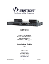
ROLINE Gigabit Ethernet Switch,
6x (5xGbE + 1x Gbic (SFP)), managed
21.14.3523
Firmware Rev 1.0 up
Installation Guide
The information contained in this document is subject to change without prior notice.

-2-
Table of Contents
1. Introduction ................................................................................................................................ 3
1.1 Features .............................................................................................................. 3
1.2 Product Panels .................................................................................................... 5
1.3 LED Indicators ..................................................................................................... 5
1.4 Specifications ...................................................................................................... 5
2. Installation ..................................................................................................................................... 8
2.1 Unpacking ........................................................................................................... 8
2.2 Safety Cautions ................................................................................................... 8
2.3 Mounting the Switch ............................................................................................ 9
2.4 Applying Power ................................................................................................... 9
2.5 Reset Button ..................................................................................................... 10
2.6 Making UTP Connections .................................................................................. 10
2.7 Making Fiber Connection................................................................................... 11
2.8 LED Indication ................................................................................................... 12
3. Manage the Switch ..................................................................................................................... 13
3.1 IP Address & Password ..................................................................................... 13
3.2 Configuring IP Address & Password via telnet ................................................... 13
3.3 Configuring IP Address via Web Interface ......................................................... 14
3.4 Reference Manuals for Web and Telnet Management ....................................... 16
3.5 Configuration for SNMP Management ............................................................... 17
3.6 SNMP MIBs....................................................................................................... 18
3.6.1 SNMP Traps ................................................................................................... 19

-3-
1. Introduction
The device is a 6-port Gigabit Ethernet switch which is featured with the following communication ports in
a small footprint box:
Five 10/100/1000Mbps Gigabit copper ports
One dual-speed SFP slot for 100Base-FX 1000Base-X
Plug and Play
The switch is shipped with factory default configuration which behaves like an unmanaged Gigabit switch
for workgroup. It provides five 10/100/1000Mbps copper ports for connections to Ethernet, Fast Ethernet,
and Gigabit Ethernet devices. With the featured auto-negotiation function, the switch can detect and
configure the connection speed and duplex automatically. The switch also provides auto MDI/MDI-X
function, which can detect the connected cable and switch the transmission wire pair and receiving pair
automatically. This auto-crossover function can simplify the type of network cables used.
Fiber Connectivity
The mini-GBIC SFP slot can be installed with an optional SFP optical fiber transceiver to support one Gigabit,
or Fast Ethernet fiber connection when needed.
Web Management
The switch is embedded with an Http server which provides management functions for advanced network
functions including Port Control, Quality of Service, and Virtual LAN functions. The management can be
performed via Web browser based interface over TCP/IP network.
1.1 Features
Five 10/100/1000Mbps RJ-45 and one dual-speed SFP slot
All copper ports support auto-negotiation and auto-MDI/MDI-X detection.
The SFP slot supports dual speed for 100BASE-FX and 1000BASE-X SFP transceivers.
Full wire speed forwarding
Supports 802.3x flow control for full-duplex and backpressure for half-duplex
Supports SFP with Digital Diagnostic Monitoring (DDM)
Provides Fiber Optical Power Alarm (OPA) function

-4-
Provides Automatic Laser Shutdown (ALS) function
Management:
- HTTP/HTTPS/SSHv2/CLI telnet/SNMP v1/v2c/v3/RMON
- DHCP/DHCPv6 client, DHCP relay, DNS client, NTPv4
- IPv6 support, System Syslog, Configuration down/upload, Software upload
Security:
- NAS, 802.1X, MAC-based/Web/CLI authentication
- IP MAC binding, TACACS+, IP source guard
Layer 2:
- QoS, 802.1Q/MAC-based/Protocol-based/Private/IP subnet VLAN, Port Isolation
- Storm control for UC/MC/BC packets, Static MAC configuration
- IGMP v2/v3 snooping, MLD v1/v2 snooping, DHCP snooping
- Multiple Spanning Tree - MSTP. RSTP, STP
Specific SNMP implementation:
- Private MIB for reading DDM status
- Private MIB for remote boot the device over SNMP
- Private MIB for TFTP firmware update over SNMP
- Private MIB for configuring OPA function
- Private MIB for configuring ALS function
- OPA alarm traps

-5-
1.2 Product Panels
The following figure illustrates the front panel and rear panel of the switch:
1.3 LED Indicators
LED Function
POWER Power status
LNK/1000M/ACT Network port 1000Mbps link status (Port 1 - Port 5)
LNK/100M/ACT Network port 100Mbps link status (Port 1 - Port 5)
LNK/10M/ACT Network port 10Mbps link status (Port 1 - Port 5)
P6 1G Port 6 1000Mbps link status
P6 100M Port 6 100Mbps link status
1.4 Specifications
10/100/1000 Copper Ports (Port 1 ~ Port 5)
Compliance IEEE 802.3 10Base-T, IEEE 802.3u 100Base-TX,
IEEE 802.3u 1000Base-T
Connectors Shielded RJ-45 jacks
Pin assignments Auto MDI/MDI-X detection
Configuration Auto-negotiation or software control
Transmission rate 10Mbps, 100Mbps, 1000Mbps
Duplex support Full/Half duplex
Network cable Cat.5 UTP

-6-
Dual-speed SFP Slot (Port 6)
Compliance IEEE 802.3u 100Base-FX
IEEE 802.3z 1000Base-SX/LX (mini-GBIC)
Connectors SFP for optional SFP type fiber transceivers
Configuration Auto 1000Mbps, Full duplex
Forced 100Mbps, Full duplex
Transmission rate 100Mbps and 1000Mbps
Network cables MMF 50/125 62.5/125, SMF 9/125
Eye safety IEC 825 compliant
Switch Functions
MAC Addresses Table 8K entries
Forwarding & filtering Non-blocking, full wire speed
Switching technology Store and forward
Maximum packet length 9.6K bytes
IP Multicast groups 8192 supported
Flow control IEEE 802.3x pause frame base for full duplex operation
Back pressure for half duplex operation
VLAN function Port-based VLAN and IEEE 802.1Q Tag-based VLAN
4095 VLANs supported, IVL support
QoS function Port-based, 802.1p-based, IP DSCP-based
Port control Port configuration control via software management
Storm control Broadcast, Multicast storm protection control via software management
Aggregation Link aggregation (port trunking)
Port Mirroring Mirror receives frames to a sniffer port
Software Management Functions
Interfaces Web browser
Management objects System configuration - IP settings, Name, Password
Port configuration control and status, VLAN function settings
Port Link Aggregation function settings
Link Aggregation LACP settings, RSTP settings
802.1X port access control, Port mirroring settings
QoS function settings, Storm protection control settings
Port statistic, LACP status, RSTP status
Configuration file backup and restore
Reboot, restore factory default, update firmware

-7-
DC Power Input
Interfaces DC Jack ( -D 6.3mm / + D 2.0mm)
Operating Input Voltages +5V - 30VDC(+/-5%) via external power adapter
Power consumption 5.4W @12V (DC IN)
6W @5V (DC IN)
Mechanical
Dimension (base) 144 x 104.5 x 26 mm
Housing Enclosed metal with no fan
Mounting Desktop mounting, wall mounting
Environmental
Operating Temperature Typical -10℃ ~ +45℃ (Main device)
(* The operating temperature range of the bundled power adapter may differ from
the temperature range of the main device.)
Storage Temperature -40℃ ~ +85℃
Relative Humidity 5% ~ 95%

-8-
2. Installation
2.1 Unpacking
The product package contains:
The switch unit
One power adapter
One product CD-ROM
2.2 Safety Cautions
To reduce the risk of bodily injury, electrical shock, fire and damage to the product, observe the following
precautions:
Do not service any product except as explained in your system documentation.
Opening or removing covers may expose you to electrical shock.
Only a trained service technician should service components inside these compartments.
If any of the following conditions occur, unplug the product from the electrical outlet and replace
the part or contact your trained service provider:
- The power cable, extension cable, or plug is damaged.
- An object has fallen into the product.
- The product has been exposed to water.
- The product has been dropped or damaged.
- The product does not operate correctly when you follow the operating instructions.
Do not push any objects into the
openings of your system. Doing so can cause fire or electric
shock by shorting out interior components.
Operate the product only from the type of external power source indicated on the electrical ratings
label. If you are not sure of the type of
power source required, consult your service provider or
local power company.

-9-
2.3 Mounting the Switch
The switch can be mounted on a desktop or shelf or a wall. Make sure that there is proper heat dissipation
from and adequate ventilation around the device. Do not place heavy objects on the device.
2.4 Applying Power
Before you begin the installation, check the AC voltage of your area. The AC power adapter which is used
to supply the DC power for the unit should have the AC voltage matching the commercial power voltage in
your area.
The AC Power Adapter Specifications
AC input: AC power voltage of your area - AC100V, 120V, 230V, 240V
DC output: DC5V / DC7.5V / DC12V / DC24V
Power: 9W min.
Steps to apply the power to the product are:
1. Connect power adapter DC plug to the DC input jack located on the back of the unit before connecting
to the AC outlet.
2. Connect the power adapter to the AC outlet.
3. Check Power LED indication.
Note: Before you begin the installation, check the AC voltage of your area. The AC power adapter which is
used to supply the DC power for the unit should have the AC voltage matching the commercial power voltage
in your area.

-10-
2.5 Reset Button
The reset button is used to perform a reset to the switch. It is not used in normal cases and can be used for
diagnostic purpose. If any network hanging problem is suspected, it is useful to push the button to reset the
switch without turning off the power. Check whether the network is recovered.
The button can also be used to restore the software configuration settings to factory default values.
The operations are:
Operation Function
Press the button more than 5 seconds when power up Restore all factory default settings
Press the button and release during switch operation Reboot the switch
2.6 Making UTP Connections
The 10/100/1000 RJ-45 copper ports supports the following connection types and distances:
Network Cables
10BASE-T: 2-pair UTP Cat. 3,4,5 , EIA/TIA-568B 100-ohm
100BASE-TX: 2-pair UTP Cat. 5, EIA/TIA-568B 100-ohm
1000BASE-T: 4-pair UTP Cat. 5 or higher (Cat.5e is recommended), EIA/TIA-568B 100-ohm
Link distance: Up to 100 meters
Auto MDI/MDI-X Function
This function allows the port to auto-detect the twisted-pair signals and adapts itself to form a valid MDI to
MDI-X connection with the remote connected device automatically. No matter a straight through cable or
crossover cable is connected, the ports can sense the receiving pair automatically and configure itself to match
the rule for MDI to MDI-X connection. It simplifies the cable installation.
Auto-negotiation Function
The ports are featured with auto-negotiation function and full capability to support connection to any Ethernet
devices. The port performs a negotiation process for the speed and duplex configuration with the connected
device automatically when each time a link is being established. If the connected device is also auto-
negotiation capable, both devices will come out the best configuration after negotiation process. If the
connected device is incapable in auto-negotiation, the switch will sense the speed and use half duplex for the
connection.
Port Configuration Management
For making proper connection to an auto-negotiation incapable device, it is suggested to use port control
function via software management to set forced mode and specify speed and duplex mode which match the
configuration used by the connected device.

-11-
2.7 Making Fiber Connection
The dual-speed SFP slot must be installed with an SFP fiber transceiver for making fiber connection. Your
switch may come with one SFP transceiver pre-installed when it is shipped.
Installing SFP Fiber Transceiver
To install an SFP fiber transceiver into SFP slot, the steps are:
1. Turn off the power to the switch.
2. Insert the SFP fiber transceiver into the SFP slot. Normally, a bail is provided for every SFP transceiver.
Hold the bail and make insertion.
3. Until the SFP transceiver is seated securely in the slot, place the bail in lock position.
Connecting Fiber Cables
LC connectors are commonly equipped on most SFP transceiver modules. Identify TX and RX connector
before making cable connection. The following figure illustrates a connection example between two fiber
ports:
Make sure the Rx-to-Tx connection rule is followed on the both ends of the fiber cable.
Network Cables
Multimode (MMF) - 50/125, 62.5/125
Single mode (SMF) - 9/125
Port Speed Configuration
There are three options for configuring port speed via software for the SFP Port. The options are:
Port Mode Description
Auto Auto-detection for the type of the installed SFP transceiver by reading DDM data
100Mbps transceiver: Non-auto-negotiation (forced), 100Mbps, full duplex
1000Mbps transceiver: Auto-negotiation, 1000Mbps, full duplex
100 Mbps FDX Non-auto-negotiation (forced), 100Mbps, full duplex
1 Gbps FDX Auto-negotiation, 1000Mbps, full duplex

-12-
2.8 LED Indication
LED Function State Interpretation
POWER Power status ON The power is supplied to the switch.
OFF The power is not supplied to the switch.
LNK/1000M/ACT Port link status ON A 1000M link is established. (No traffic)
BLINK Port link is up and there is traffic.
OFF Port link is down.
LNK/100M/ACT Port link status ON A 100M link is established. (No traffic)
BLINK Port link is up and there is traffic.
OFF Port link is down.
LNK/10M/ACT Port link status ON A 10M link is established. (No traffic)
BLINK Port link is up and there is traffic.
OFF Port link is down.
P6 1G Port 6 1G link status ON A 1000Mbps link is established on Port 6.
BLINK Port 6 link is up and there is traffic.
OFF Port 6 link is down.
P6 100M Port 6 100M link status ON A 100Mbps link is established on Port 6.
BLINK Port 6 link is up and there is traffic.
OFF Port 6 link is down.

-13-
3. Manage the Switch
The switch provides the following methods to configure and monitor the switch as follows:
Making in-band management via web interface over TCP/IP network
Making in-band management via telnet CLI over TCP/IP network
Making in-band SNMP management over TCP/IP network
3.1 IP Address & Password
The IP Address is an identification of the switch in a TCP/IP network. Each switch should be designated a
new and unique IP address in the network. The switch is shipped with the following factory default settings
for software management:
Default IP address of the switch: 192.168.0.2 / 255.255.255.0
The switch uses local authentication instead of RADIUS authentication with factory defaults.
Fixed Username: admin
Default password:
No password is required with factory default. However, the password is used for local authentication in
accessing to the switch via telnet and Http web-based interface. For security reason, it is recommended to
change the default settings for the switch before deploying it to your network.
3.2 Configuring IP Address & Password via telnet
[IP Address] setting command is in IP command group.
>IP Setup [<ip_addr>] [<ip_mask>] [<ip_router>] [<vid>]
Parameters:
<ip_addr> : IP address (a.b.c.d)
<ip_mask> : IPv4 subnet mask (a.b.c.d)
<ip_router> : IPv4 router (a.b.c.d)
<vid> : VLAN ID (1-4095)
[IPv6 Address] setting command is also in IP command group.
>IP IPv6 Setup [<ipv6_addr>] [<ipv6_prefix>] [<ipv6_router>]
Parameters:
<ipv6_addr> : IPv6 address is in 128-bit records represented as eight fields of up to four
hexadecimal digits with a colon separates each field (:).
<ipv6_prefix> : IPv6 subnet mask

-14-
<ipv6_router> : IPv6 router
[Password] setting command is also in Security/Switch/Users command group.
Security Switch Users Configuration
Security Switch Users Add <user_name> <password> <privilege_level>
Security Switch Users Delete <user_name>
Refer to “Operation manual for telnet management”.
3.3 Configuring IP Address via Web Interface
Start Web Browser
Start your browser software and enter the default IP address of the switch unit to which you want to connect.
The IP address is used as URL for the browser software to search the device.
URL: http:/192.168.0.2/
Login to Switch Unit
When browser software connects to the switch unit successfully, a Login screen is provided for you to login
to the device as the left display below:
Enter the following default values in the login page:
Default username: admin
Default password:
No password is required.
Click OK to login into the switch.

-15-
Web Page after a Successful Login
Select [Configuration] -> [System] -> [IP] to configure IP address
Configuration Description
DHCP Client Enable the DHCP client by checking this box.
IP Address Provide the IP address of this switch unit.
IP Mask Provide the IP mask of this switch unit.
IP Router Provide the IP address of the default router for this switch unit.
VLAN ID Provide the managed VLAN ID. The allowed range is 1 through 4095.
DNS Server Provide the IP address of the DNS Server in dotted decimal notation.
DNS Proxy When DNS proxy is enabled, DUT will relay DNS requests to the current
configured DNS server on DUT, and reply as a DNS resolver to the client device

-16-
on the network.
Save Click to save the changes.
Reset Click to undo any changes made locally and revert to previously saved values.
Renew Click to renew DHCP. This button is only available if DHCP is enabled.
3.4 Reference Manuals for Web and Telnet Management
The following operation manuals are also provided separately for Telnet and Web management:
Operation manual - telnet management xxxxxx.doc
Operation manual - web management xxxxx.doc
The manuals describe the detailed commands and information.

-17-
3.5 Configuration for SNMP Management
The switch supports SNMP v1, SNMP v2c, and SNMP v3 management. Make sure the related settings are
well-configured for the switch before you start the SNMP management from an SNMP manager.
Using Telnet Interface
The following are available commands in telnet SNMP command group to configure SNMP-related settings:
>SNMP Configuration
>SNMP Mode [enable|disable]
>SNMP Version [1|2c|3]
>SNMP Read Community [<community>]
>SNMP Write Community [<community>]
>SNMP Trap Mode [enable|disable]
>SNMP Trap Version [1|2c|3]
>SNMP Trap Community [<community>]
>SNMP Trap Destination [<ip_addr_string>]
>SNMP Trap IPv6 Destination [<ipv6_addr>]
>SNMP Trap Authentication Failure [enable|disable]
>SNMP Trap Link-up [enable|disable]
>SNMP Trap Inform Mode [enable|disable]
>SNMP Trap Inform Timeout [<timeout>]
>SNMP Trap Inform Retry Times [<retries>]
>SNMP Trap Probe Security Engine ID [enable|disable]
>SNMP Trap Security Engine ID [<engineid>]
>SNMP Trap Security Name [<security_name>]
>SNMP Engine ID [<engineid>]
>SNMP Community Add <community> [<ip_addr>] [<ip_mask>]
>SNMP Community Delete <index>
>SNMP Community Lookup [<index>]
>SNMP User Add <engineid> <user_name> [MD5|SHA] [<auth_password>] [DES] [<priv_password>]
>SNMP User Delete <index>
>SNMP User Changekey <engineid> <user_name> <auth_password> [<priv_password>]
>SNMP User Lookup [<index>]
>SNMP Group Add <security_model> <security_name> <group_name>
>SNMP Group Delete <index>
>SNMP Group Lookup [<index>]
>SNMP View Add <view_name> [included|excluded] <oid_subtree>
>SNMP View Delete <index>
>SNMP View Lookup [<index>]
>SNMP Access Add <group_name> <security_model> <security_level> [<read_view_name>]

-18-
[<write_view_name>]
>SNMP Access Delete <index>
>SNMP Access Lookup [<index>]
Using Web Interface
Select [Configuration] -> [Security] -> [SNMP]:
The commands supports configuration for:
- Basic system configuration for SNMP v1 and SNMP v2c
- Basic system configuration for SNMP v1 trap, SNMP v2c trap and SNMP v3 trap
- Communities that permit to access to SNMPv3 agent
- USM (User-based Security Model) user table for SNMPv3
- VACM (View-based Access Control Model) Viewer table for SNMPv3
- Group table for SNMPv3
- Accesses group table for SNMPv3
3.6 SNMP MIBs
The switch provides the following SNMP MIBs:
- RFC 1213 - MIB II
- RFC 2674 - QBridge MIB (VLAN MIB)
- RFC 2819 - RMON (Group 1, 2. 3 & 9)
- RFC 2863 - Interface Group (IF) MIB
- RFC 3411 - SNMP Management Frameworks
- RFC 3414 - User Based Security Model (USM)
- RFC 3415 - View Based Access Control Model (VACM)
- RFC 3621 - Power Ethernet MIB
- RFC 3635 - EtherLike MIB
- RFC 3636 - 802.3 Medium Attachment Units (MAUs) MIB
- RFC 4133 - Entity MIB
- RFC 4188 - Bridge MIB
- RFC 4668 - RADIUS Authentication Client MIB
- RFC 5519 - Multicast Group Membership Discovery (MGMD) MIB
- IEEE 802.1 MSTP MIB
- IEEE 802.1AB LLDP MIB

-19-
- IEEE 802.1X Port Access Entity (PAE) MIB
- TIA 1057 LLDP Media Endpoint Discovery (MED) MIB
- IEEE 802.1-Q-BRIDGE MIB
- Private SFPDDM MIB (Read DDM status of the SFP ports)
- Private reboot MIB (Remote boot over SNMP)
- Private TFTP firmware update MIB (TFTP Firmware update over SNMP)
- Private OPA function MIB (OPA configuration for the SFP ports)
- Private ALS function MIB (ALS configuration for the SFP ports)
One product MIB file is also available in the product CD for SNMP manager software.
3.6.1 SNMP Traps
In addition to the SNMP standard traps, the device is equipped with private OPA alarm traps.
The traps are:
- Alarm trap – SFP port TX power lower than the minimal value
- Alarm trap – SFP port TX power higher than the maximal value
- Normal trap – SFP port TX power back to normal (higher than the minimal value)
- Normal trap – SFP port TX power back to normal (lower than the maximal value)
/