Page is loading ...

KGS-2421
Managed 24-Port Gigabit Ethernet Switches
with 4 SFP Slots
Installation Guide
DOC.101213
-1-

(C) 2010 KTI Networks Inc. All rights reserved. No part of this documentation may be reproduced in any form
or by any means or used to make any directive work (such as translation or transformation) without permission
from KTI Networks Inc.
KTI Networks Inc. reserves the right to revise this documentation and to make changes in content from time to
time without obligation on the part of KTI Networks Inc. to provide notification of such revision or change.
For more information, contact:
United States KTI Networks Inc.
P.O. BOX 631008
Houston, Texas 77263-1008
Phone: 713-2663891
Fax: 713-2663893
E-mail: [email protected]
URL: http://www.ktinet.com/
International Fax: 886-2-26983873
E-mail: [email protected]
URL: http://www.ktinet.com.tw/
-2-

The information contained in this document is subject to change without prior notice.
Copyright (C) All Rights Reserved.
TRADEMARKS
Ethernet is a registered trademark of Xerox Corp.
FCC NOTICE
This device complies with Part 15 of the FCC Rules. Operation is subject to the following two conditions: (1)
This device may not cause harmful interference, and (2) This device must accept any interference received,
including the interference that may cause undesired operation.
CE NOTICE
Marking by the symbol indicates compliance of this equipment to the EMC directive of the European
Community. Such marking is indicative that this equipment meets or exceeds the following technical
standards:
EMC Class A
EN55022:2006/A1:2007
EN61000-3-2:2006
EN61000-3-3:1995/A1:2001/A2:2005 Class A
EN 55024:1998/A1:2001/A2:2003
IEC 61000-4-2:2001
IEC 61000-4-3:2002/A1:2002
IEC 61000-4-4:2004
IEC 61000-4-5:2001
IEC 61000-4-6:2003
IEC 61000-4-8:2001
IEC 61000-4-11:2001
-3-

-4-
Table of Contents
1. Introduction......................................................................................................................................................5
1.1 Features.................................................................................................................................6
1.2 Product Panels.......................................................................................................................8
1.3 LED Indicators .......................................................................................................................9
1.4 Specifications.........................................................................................................................9
2. Installation......................................................................................................................................................11
2.1 Unpacking............................................................................................................................11
2.2 Safety Cautions.................................................................................................................... 11
2.3 Mounting the Switch.............................................................................................................12
2.4 AC Power Supply................................................................................................................. 13
2.5 DC Power Supply.................................................................................................................13
2.6 Reset Button ........................................................................................................................ 14
2.7 Making UTP Connections .................................................................................................... 15
2.8 Making Fiber Connection.....................................................................................................16
2.9 LED Indication......................................................................................................................17
2.10 Making Console Connection..............................................................................................18
3. Manage the Switch........................................................................................................................................19
3.1 IP Address & Password ....................................................................................................... 19
3.2 Configuring IP Address & Password via console and telnet................................................ 19
3.3 Configuring IP Address & Password via Web Interface....................................................... 20
3.4 Reference Manuals for Web, Console, Telnet Management............................................... 22
3.5 Configuration for SNMP Management................................................................................. 23
3.6 SNMP MIBs ......................................................................................................................... 24

1. Introduction
The 24-port Managed Gigabit Ethernet Switches are standard L2 switches that meets all IEEE 802.3/u/x/z
Gigabit, Fast Ethernet specifications. The switches have 20 10/100/1000Mbps copper ports and 4 combo ports
with copper and Gigabit SFP slots. The switches support console CLI, Telnet CLI, Web GUI and SNMP
interface for switch management. The network administrator can logon the switch to monitor and configure
port operating mode, Quality of Service, and powerful L2 switching functions such as VLAN, IGMP, RSTP etc.
In addition, the switches are also featured with security functions such as IEEE802.1x and ACL control to
make them suitable for office applications.
The switch is featured with the following switched ports and advantages in a 1U rack box:
20 10/100/1000Mbps Gigabit copper ports
4 combo ports - 10/100/1000Mbps copper & 1000Base-X SFP
Model Definition
Model Description Management Power Input
KGS-2421-S AC powered model Managed AC 100 ~ 240V
KGS-2421-D DC powered model Managed DC 40 ~ 72V
Plug and Play
The switch is shipped with factory default configuration which behaves like an unmanaged Gigabit switch for
workgroup. It provides 24 10/100/1000Mbps copper ports for connections to Ethernet, Fast Ethernet, and
Gigabit Ethernet devices. With the featured auto-negotiation function, the switch can detect and configure the
connection speed and duplex automatically. The switch also provides auto MDI/MDI-X function, which can
detect the connected cable and switch the transmission wire pair and receiving pair automatically. This
auto-crossover function can simplify the type of network cables used.
-5-

-6-
Fiber Connectivity
Four combo ports provide four 1000M SFP slots, which can be installed with optional SFP optical fiber
transceivers to support four Gigabit 1000Base-X fiber connections respectively when needed.
Management
The switch is embedded with an Http server and telnet server which provide management functions for
advanced network functions including Port Control, Quality of Service, and Virtual LAN functions. The
management can be performed via Web browser based interface or telnet CLI over TCP/IP network. The
switch also provides SNMP agent to support management from an SNMP manager.
AC & DC Power Options
In addition to standard AC power input, the switches provide DC options for applications with DC power
system.
1.1 Features
z Provides 24 10/100/1000Mbps RJ-45 and four Gigabit SFP slots (4 combo ports)
z Provides in-band console CLI, web and SNMP management interfaces
z All copper ports support auto-negotiation and auto-MDI/MDI-X detection
z Power saving support
z The SFP slots support 1000BASE-X SFP transceivers
z Provides Gigabit full wire speed forwarding
z Supports 802.3x flow control for Full-duplex and backpressure for Half-duplex
z Support jumbo frames
z 19” rack mountable
z Both AC powered model and DC powered model are available for choice.
Management Features:
z Port Control
- Port Speed/Duplex Mode/Flow Control/Power saving configuration
- Port frame size control (Jumbo frame support)
z QoS
- Traffic Classification up to 4 active priorities
- Port QoS configuration
- QoS Control List for policy rules
- Port bandwidth control for ingress and egress
- Storm Control for UC, MC and BC
z Layer2

-7-
- Auto MAC address learning and ageing
- Static MAC address filtering
- Port-based and 802.1Q Tag-based VLAN
- Link Aggregation - LACP
- Rapid Spanning tree - RSTP
- Port Mirroring
- IGMP snooping
- DHCP client for IP configuration
z Security features
- Access Control List for L2/L3 protocol filtering, ingress rate limit, port copy
- Port Access Control based on IEEE 802.1X
z Management
- Web management
- Console CLI
- Telnet CLI
- Software Download via Web
- SNTP Client
- SNMP v1/v2c Agent
- SSH v2 & HTTPS
- RMON group 1, 2, 3, and 9
- Restore to default configuration
- Configuration download and upload
- System syslog
z SNMP MIBs

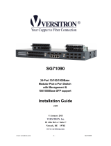
1.2 Product Panels
The following figure illustrates the front panel and rear panel of the switch:
Front panel
Rear panel – Managed models with AC power
Rear panel – Managed models with DC power
-8-

-9-
1.3 LED Indicators
LED Function
POWER Power status
Mngt Management status
1000M Port speed 1000Mbps status (Port 1 – Port 24)
Link/Act. Port link and activity status (Port 1 – Port 24)
F21 – F24 SFP Fiber is selected on Port 21 – Port 24
1.4 Specifications
10/100/1000 Copper Ports
Compliance IEEE 802.3 10Base-T, IEEE 802.3u 100Base-TX, IEEE 802.3u 1000Base-T
Connectors Shielded RJ-45 jacks
Pin assignments Auto MDI/MDI-X detection
Configuration Auto-negotiation or software control
Transmission rate 10Mbps, 100Mbps, 1000Mbps
Duplex support Full/Half duplex
Network cable Cat.5 UTP
Combo Ports (Port 21 ~ Port 24) with 10/100/1000 RJ-45 and 1000Mbps SFP
10/100/1000 Copper Port Interface
Same as above 10/100/1000 Copper Ports
Fiber interface
Compliance IEEE 802.3z 1000Base-SX/LX (mini-GBIC)
Connectors SFP slot for optional SFP type fiber transceivers
Configuration Auto/Forced, 1000Mbps, Full duplex
Transmission rate 1000Mbps
DDM support Yes
Network cables MMF 50/125 60/125, SMF 9/125
Eye safety IEC 825 compliant
Console Port
Interface RS-232, DTE type
Connector 9-pin D-sub
Switch Functions
MAC Addresses Table 8K entries

-10-
Forwarding & filtering Non-blocking, full wire speed
Switching technology Store and forward
Maximum packet length 9600 bytes (Jumbo frame support)
Flow control IEEE 802.3x pause frame base for full duplex operation
Back pressure for half duplex operation
VLAN function Port-based VLAN and IEEE 802.1Q Tag-based VLAN
VLAN support 4096 VLANs (IEEE 802.1Q)
Aggregation Static and LACP Port link aggregation (port trunking)
QoS function Ethernet type, IP-based, DSCP, TOS-based, VID-based, VLAN Tag-based packet
classification
Port rate control, storm control
Port Mirroring Mirror received frames to a sniffer port
AC Power Input
Interfaces IEC320 receptacle
Operating Input Voltages 100 ~ 240VAC
Power Consumption 34W max.
DC Power Input
Interfaces Screw-type terminal block
Operating Input Voltages +40 ~ +72VDC
Power Consumption 34W max.
Mechanical
Dimension (base) 443 x 245 x 43 mm (WxDxH)
Housing Enclosed metal
Mounting Desktop mounting, 19” rack mounting
Environmental
Operating Temperature Typical -5oC ~ +50oC
Storage Temperature -20oC ~ +85oC
Relative Humidity 10% ~ 90% non-condensing
Electrical Approvals
FCC Part 15 rule Class A
CE EMC, CISPR22 Class A
Safety LVD, IEC60950

-11-
2. Installation
2.1 Unpacking
The product package contains:
z The switch unit
z One AC power cord (AC powered Model)
z One 19” rack mounting kit
z One product CD-ROM
2.2 Safety Cautions
To reduce the risk of bodily injury, electrical shock, fire and damage to the product, observe the following
precautions.
z Do not service any product except as explained in your system documentation.
z Opening or removing covers may expose you to electrical shock.
z Only a trained service technician should service components inside these compartments.
z If any of the following conditions occur, unplug the product from the electrical outlet and replace the part
or contact your trained service provider:
- The power cable, extension cable, or plug is damaged.
- An object has fallen into the product.
- The product has been exposed to water.
- The product has been dropped or damaged.
- The product does not operate correctly when you follow the operating instructions.
z Do not push any objects into the openings of your system. Doing so can cause fire or electric shock by
shorting out interior components.
z Operate the product only from the type of external power source indicated on the electrical ratings label. If
you are not sure of the type of power source required, consult your service provider or local power
company.

2.3 Mounting the Switch
Desktop Mounting
The switch can be mounted on a desktop or shelf. Make sure that there is proper heat dissipation from and
adequate ventilation around the device. Do not place heavy objects on the device.
Rack Mounting
Two 19-inch rack mounting brackets are supplied with the switch for 19-inch rack mounting.
The steps to mount the switch onto a 19-inch rack are:
1. Turn the power to the switch off.
2. Install two brackets with supplied screws onto the switch as shown in figure below.
2. Mount the switch onto 19-inch rack with rack screws securely.
-12-

3. Turn the power to the switch on.
2.4 AC Power Supply
If the purchased switch is with AC power input, one AC power cord which meets the specification of your
country of origin was supplied in package. Before installing AC power cord to the switch, make sure the AC
power is OFF and the AC power to the power cord is turned off.
AC power input specifications
Connector: IEC320 type
Power Rating: 100 ~ 240VAC, 50/60Hz
Voltage Range: 90 ~ 264VAC
Frequency: 47 ~ 63 Hz
Power Consumption: 34W max.
2.5 DC Power Supply
If the purchased switch is with DC power input, the power connector is shown below:
-13-

DC power input specifications
Receptacle: Screw-type terminal block
Operating Voltages: +40 ~ +72VDC
Power Consumption: 34W max. @48VDC
2.6 Reset Button
The reset button is used to perform a reset to the switch. It is not used in normal cases and can be used for
diagnostic purpose. If any network hanging problem is suspected, it is useful to push the button to reset the
switch without turning off the power. Check whether the network is recovered.
The button can also be used to restore the software configuration settings to factory default values. The
operations are:
Operation Function
Press the button more than 4 seconds when power up Restore factory default settings
Press the button and release during switch operation Re-boot the switch
-14-

-15-
2.7 Making UTP Connections
The 10/100/1000 RJ-45 copper ports support the following connection types and distances:
Network Cables
10BASE-T: 2-pair UTP Cat. 3, 4, 5, EIA/TIA-568B 100-ohm
100BASE-TX: 2-pair UTP Cat. 5, EIA/TIA-568B 100-ohm
1000BASE-T: 4-pair UTP Cat. 5 or higher (Cat.5e is recommended), EIA/TIA-568B 100-ohm
Link distance: Up to 100 meters
Auto MDI/MDI-X Function
This function allows the port to auto-detect the twisted-pair signals and adapts itself to form a valid MDI to
MDI-X connection with the remote connected device automatically. No matter a straight through cable or
crossover cable are connected, the ports can sense the receiving pair automatically and configure themselves to
match the rule for MDI to MDI-X connection. It simplifies the cable installation.
Auto-negotiation Function
The ports are featured with auto-negotiation function and full capability to support connection to any Ethernet
devices. The port performs a negotiation process for the speed and duplex configuration with the connected
device automatically when each time a link is being established. If the connected device is also
auto-negotiation capable, both devices will come out the best configuration after negotiation process. If the
connected device is incapable in auto-negotiation, the switch will sense the speed and use half duplex for the
connection.
Port Configuration Management
For making proper connection to an auto-negotiation INCAPABLE device, it is suggested to use port control
function via software management to set forced mode and specify speed and duplex mode which match the
configuration used by the connected device.

2.8 Making Fiber Connection
The SFP slot must be installed with an SFP fiber transceiver for making fiber connection. Your switch may
come with some SFP transceivers pre-installed when it was shipped.
Installing SFP Fiber Transceiver
To install an SFP fiber transceiver into SFP slot, the steps are:
1. Turn off the power to the switch.
2. Insert the SFP fiber transceiver into the SFP slot. Normally, a bail is provided for every SFP transceiver.
Hold the bail and make insertion.
3. Until the SFP transceiver is seated securely in the slot, place the bail in lock position.
Connecting Fiber Cables
LC connectors are commonly equipped on most SFP transceiver modules. Identify TX and RX connector
before making cable connection.
The following figure illustrates a connection example between two fiber ports:
-16-

Make sure the Rx-to-Tx connection rule is followed on the both ends of the fiber cable.
Network Cables
Multimode (MMF) - 50/125μm, 62.5/125 μm
Single mode (SMF) - 9/125 μm
Fiber Port Configuration
For 1000M fiber application on Port 21, 22, 23, and 24, just leave the default port configuration Auto for fiber
connection.
2.9 LED Indication
LED Function State Interpretation
POWER Power status ON The power is supplied to the switch.
OFF The power is not supplied to the switch.
Mngt Management status OFF The switch is in initialization and diagnostics.
BLINK The switch is initialized completely with diagnostic error.
ON The switch is initialized completely and normal.
1000M Port speed status ON A speed of 1000Mbps is selected.
OFF A speed of 10/100Mbps is selected.
Link/Act. Port link status ON A link is established. (No traffic)
BLINK Port link is up and there is traffic.
-17-

-18-
OFF Port link is down.
F21 F21 status OFF RJ-45 copper connection is selected on Port 21.
ON SFP fiber connection is selected on Port 21.
F22 F22 status OFF RJ-45 copper connection is selected on Port 22.
ON SFP fiber connection is selected on Port 22.
F23 F23 status OFF RJ-45 copper connection is selected on Port 23.
ON SFP fiber connection is selected on Port 23.
F24 F24 status OFF RJ-45 copper connection is selected on Port 24.
ON SFP fiber connection is selected on Port 24.
2.10 Making Console Connection
Console port is a DB9 connector. It serves as an RS-232 DTE port.
Pin Definitions
Pin 2 RXD
Pin 3 TXD
Pin 5 GND
Pin 1,4,6-9 NC
Use simple RS232 null modem without handshaking to connect the console port to PC’s DB9 COM port as
follows:
Console Pins COM Port Pins
Pin 2 RXD ----------------------------- Pin 3 TXD
Pin 3 TXD ----------------------------- Pin 2 RXD
Pin 5 GND ----------------------------- Pin 5 GND
Baud Rate Information
Baud rate: 115200
Data bits: 8
Parity: none
Stop bit: 1
Flow control: disabled

-19-
3. Manage the Switch
The switch provides the following methods to configure and monitor the switch as follows:
z Making out of band management via RS-232 console port
z Making in-band management via telnet interface over TCP/IP network
z Making in-band management via web interface over TCP/IP network
z Making in-band SNMP management over TCP/IP network
3.1 IP Address & Password
The IP Address is an identification of the switch in a TCP/IP network. Each switch should be designated a new
and unique IP address in the network. The switch is shipped with the following factory default settings for
software management:
Default IP address of the switch: 192.168.0.2 / 255.255.255.0
The switch uses local authentication instead of RADIUS authentication with factory defaults.
Fixed Username: admin
Default password:
No password is required with factory default. However, the password is used for local authentication in
accessing to the switch via console, telnet and Http web-based interface. For security reason, it is
recommended to change the default settings for the switch before deploying it to your network.
3.2 Configuring IP Address & Password via console and telnet
[Password] setting command is in System command group.
>System password <password>
↵
Parameters:
<password>: The allowed password string length is 0 to 31, and the allowed content is the ASCII
characters from 32 to 126.
[IP] command group is used to configure the switch’s IP settings. The command syntax is:
>IP DHCP [enable|disable]
>IP Setup [<ip_addr>] [<ip_mask>] [<ip_router>] [<vid>]
Parameters:
<ip_addr>: IP address (a.b.c.d), default: Show IP address

<ip_mask>: IP subnet mask (a.b.c.d), default: Show IP mask
<ip_router>: IP router (a.b.c.d), default: Show IP router
<vid>: VLAN ID (1-4095), default: Show VLAN ID
3.3 Configuring IP Address & Password via Web Interface
Start Web Browser
Start your browser software and enter the default IP address of the switch unit to which you want to connect.
The IP address is used as URL for the browser software to search the device.
URL: http:/192.168.0.2/
Login to Switch Unit
When browser software connects to the switch unit successfully, a Login screen is provided for you to login to
the device as the left display below:
Enter the following default values in the login page:
Fixed User Name: admin
Default password:
No password is required.
Click OK to login into the switch.
-20-
/