Page is loading ...

Texmate, Inc. Tel. (760) 598-9899 • www.texmate.com TL_manual (d0007) Page 1
✔ LEOPARD FAMILY: More than 38 differ-
ent Plug-in I-Series Input Signal Conditioners
are approved for Texmate’s Leopard Family of
meters. Some examples are shown on pages 8-10.
See www.texmate.com for an up to date listing.
Input Specs: ..............Depends on Input signal conditioner
A/D Converter: ..........14 bit single slope
Accuracy: ..................±(0.05% of reading + 2 counts)
Temp. Coeff.: .............100 ppm/°C (Typical)
Warm up time: ...........2 minutes
Conversion Rate: ......5 conversions per second (Typical)
Remote Display: .......4 digit 0.56" Red LED Remote dis-
play. (Optional)
Range
–1999 to 9999 counts.
Polarity: .....................Assumed positive. Displays – negative
Decimal Selection: ....Front panel button selectable, X•X•X•X•
Positive Overrange: ..Top segments of digital display flash
Negative Overrange: .Bottom segments of digital display flash
Relay Output: ............Two 9 Amp Form C relays.
Analog Output: .........Isolated 16 bit user scalable mA or V
AIC (mA out) ...........
4-20 mA @ 0 to 500Ω max loop resistance
AIV (volts out) .......... 0-10 V DC @ 500 Ω or higher resistance
Power Supply: ...........AC/DC Auto sensing wide range supply
PS1 (std) ................
85-265 VAC 50-400Hz / 95-300 VDC @ 3.5W
PS2 .........................
15-48 VAC 50-400Hz / 10-72 VDC @ 3.5W
Operating Temp.: ......0 to 50 °C
Storage Temp: ...........–20 °C to 70 °C.
Relative Humidity: ....95% (non condensing)
Case Dimensions: ....DIN Rail Mount
22.5mm x 102.4mm x 128.7mm
(Width x Height x Depth)
Plus 11.8 mm (0.47”) for Right-angled
connectors.
Weight: .......................7.5 oz., 9.0 oz when packed
Case Dimensions . . . . . . . . . . . 12
Connector Pinouts . . . . . . . . . . . . .7
Controls and Indicators . . . . . . . . .2
Decimal Point & Brightness Selection
.5
Digital Calibration Mode . . . . . . . .4
Digital Calibration Procedure. . . . .4
Digital Span Selection for Analog
Range Output . . . . . . . . . . . . . . . .5
Functional Diagram . . . . . . . . . . . .7
General Features. . . . . . . . . . . . . .1
Glossary of Prog. Symbols . . . . . .2
Input Module Analog Cal.
. . . . 11-12
Input Module Comp. Glossary
. . . .11
Input Module Compatibility . . . . . .1
I-Series Input Signal Conditioning
Modules
. . . . . . . . . . . . . . . . . . 8-10
Installation Guidelines . . . . . . . . 13
Ordering Information . . . . . . . . . 14
Select Input Range and Analog
output . . . . . . . . . . . . . . . . . . . . . 13
Setpoint Setting & RelayConfiguration
Mode
. . . . . . . . . . . . . . . . . . . . . . . .6
Software Features . . . . . . . . . . . . .1
Software Logic Tree. . . . . . . . . . . .3
Specifications. . . . . . . . . . . . . . . . .1
Two Point Analog Output
Range Setting and Calibration . . .5
An economically smart programmable transmitter relay with
isolated 4 to 20 mA retransmission or control loop output
capability for measurementand control applications.
• External transmitters or signal conditioners can be eliminated
by direct connection of the sensor output to more than
38 Plug-in Input Signal Conditioners that include:
– AC/DC Current – Pressure – Resistance
– AC/DC Voltage – Process – *Temperature
– Load Cell – Prototype – 4 to 20 mA
*See models TLH for higher accuracy digitally linearized thermocou-
ple and RTD
• Isolated 16 bit analog output. User or factory scalable to 4 to 20 mA,
0 to 20 mA or 0 to 10 V across any desired
digital span from ± one count to the full scale range of – 1999 to 9999
(12000 counts).
• Auto-sensing AC/DC power supply. For voltages between
85-265 V AC / 95-300 V DC (PS1) or 15-48 V AC / 10-72 V DC
(PS2).
• 24 V DC excitation is available to power external transmitters
and 5 or 10 V DC excitation is available for resistance bridge type
sensors such as Load Cells and Pressure Transducers.
• Automatic intelligent averaging smooths noisy signals, while
providing a fast display response to real level changes.
• Remote Diplay Option only.
General Features Input Module Compatibility
Specifications
Software Features
Index
• Three-button programming from the optional remote display
(UP, DOWN and PROGRAM buttons).
• Front panel selectable
four-level brightness control of digital dis-
play, and setpoint LEDs when diplay is used
.
•
Two programmable setpoints.
• Relay activation can be selected to occur above (HI) or below
(LO) each setpoint.
• Hysteresis, Delay on make and delay on break for both set-
points.
• Peak and Valley. View and Reset.(only when diplsya is used)
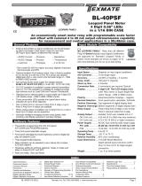
LEOPARD FAMILY
TL
Leopard Series
Transmitter and Controller
LEOPARD

Texmate, Inc. Tel. (760) 598-9899 • www.texmate.comPage 2 TL_manual (d0007)
Symbol Explanation
This symbol represents the
OPERATIONAL DISPLAY.
This is the PROGRAM button.
This is the UP button.
This is the DOWN button.
When a button is shown, press and
release it to go onto the next step in the
direction indicated by the arrow. When two
or more buttons are shown, each with an
arrow, this indicates that there is a number
of programming choices.
When two buttons are shown side by side
and enclosed by a dotted line, they must
be pressed at the same time then released
to go onto the next programming step.
If the display is shown with XXXX it means
the value displayed will be the previously set
value. When a number is shown it indicates
the initial factory default setting or a specific
“example number”.
P
P
When two displays are shown together with
bursts, this indicates that the display is
toggling (flashing) between the name of the
function and the value.
Text or numbers shown between square
brackets in a procedure indicate the pro-
gramming code name of the function or the
value displayed on the meter display.
When the
and
buttons are shown
together, the display value can be increased
by pressing and releasing the
button
or decreased by pressing and releasing the
button.
When the
and
buttons are shown
with two displays, either display can be
selected by pressing and releasing the
or
buttons.
When there are more than two display selec-
tions they are shown in brackets below the
first display and are also selectable by press-
ing and releasing the
or
buttons.
To explain software programming procedures, logic diagrams are
used to visually assist in following the programming steps. The
fol-lowing symbols are used to represent various functions and
associated display elements of the meter:
[Span]
[10000]
[LhLh]
[hLhh]
[LLLh]
Front Panel Buttons
Program Button
The
P
button is used to move from one program step to the next.
When pressed at the same time as the button, it initiates the
calibration mode. When pressed at the same time as the but-
ton, it initiates the setpoint setting mode.
Up Button
When in the operational display, pressing the button alone,
allows you to view and reset the Peak and Valley (Highest and
Lowest Readings.)
When in the calibration mode or the setpoint setting mode the
button is used to increase the value of the displayed parameter.
Down Button
When in the operational display, pressing the button alone,
allows you to view, but not change, the setting of setpoint 1&2.
When in the calibration mode or the setpoint setting mode the
button is used to decrease the value of the displayed parameter.
Glossary of Programming Symbols
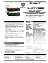
Controls and Indicators
UP ARROW
BUTTON
DOWN ARROW
BUTTON
Setpoint
Annunciator
LEDs
SP2
SP1
PROGRAM
BUTTON P
Setpoint Setpoint
Annunciator Annunciator
SP2SP2
Optional Remote Display for
Field Programming and Setup
is needed

Texmate, Inc. Tel. (760) 598-9899 • www.texmate.com TL_manual (d0007) Page 3
SETPOINT SETTING AND
RELAY CONFIGURATION MODE
See Page 6
Set Setpoint 1
(SP1)
Delay-on-Make
(doM)
Delay-on-Break
(dob)
Setpoint 2
(SP2)
Hysteresis
(hYSt)
Hysteresis
(hYSt)
Delay-on-Make
(doM)
Delay-on-Break
(dob)
Peak
Reset
PEAK
Reset
VALY
Setpoint 1
(SP1)
Setpoint 2
(SP2)
MAIN MENU
Operational Display
SETPOINT
VIEW ONLY MODE
PEAK & VALLEY
VIEW & RESET
Sub-menu
MODE
Calibration
Mode
Calibration
Mode
DECIMAL POINT AND
BRIGHTNESS SELECTION
See Page 5
Valley
Calibrate
Analog
Output
Lo
Calibrate
Analog
Output
Hi
Span
Zero
[X•XXX]
[XX•XX]
[XXX•X]
[XXXX•]
[XXXX]
[2]
[3]
[4]
Decimal Point
(dp)
Display
Brightness (br)
Err. Any new setting
canceled and previous
settings are retained
TWO POINT ANALOG OUTPUT
RANGE SETTING AND
CALIBRATION
SEE PAGE 5
TWO POINT DIGITAL
CALIBRATION MODE
SEE PAGE 4
DIGITAL SPAN
SELECTION FOR ANALOG
RANGE OUTPUT
See Page 5
Default Setting Value:
cLo:
4mA -- 2250
0V -- 000
chi:
20mA -- 100
10V -- 325
Pump
[PUM]
Pump On Pump Off
When PUM is selected ON,
and SP2 is set at a value
higher than SP1, the SP1
relay will operate in
a special "pump on pump off"
Hysteresis mode. SP2 acts
as the upper limit and SP1
acts as the lower limit of the
Hysteresis Band.
For filling applications, rLYS
should be set to LhLh. SP1 will
then activate for inputs less than
the SP1 setpoint, and remain
ON until the SP2 setpoint is
reached.
For emptying applications,
rLYS should be set to hhhh.
SP1 will then activate for inputs
greater than the SP2 setpoint,
and remain ON until the SP1
setpoint is reached.
L or H
for SP1
L or H
for SP2
Relays Activation
[rLYS]
(h) High
the relay energizes
when the setpoint
is exceeded
(L) Low
the relay
energizes below
the setpoint.
The TL is an intelligent transmitter with a hierarchical software
structue designed for easy programming and operation, as
shown below in the software logic tree.
After the meter has been powered up, the
four digits light up for three seconds and
then settle to the operational display indicat-
ing the input signal.
15 Second Program Timeout
The meter has a 15 second program timeout. If
no buttons are pressed for 15 seconds, at any
stage of the programming sequence the meter
will exit the programming mode and return to
the operational display. Any program changes
that were made prior to pressing the
P
button
in the preceding step will not be saved.
Software Logic Tree

Texmate, Inc. Tel. (760) 598-9899 • www.texmate.comPage 4 TL_manual (d0007)
This mode enables the meter to be calibrated with an automatic scale factor calculation, by applying a high input signal, entering the
desired reading for that signal, then applying a zero or low input signal, and then entering the desired 0 or low reading. The meter
then automatically calculates and programs in the requisite scale factor, within the following parameters.
1. Positive and negative signals may be applied, but the difference between the high and the low signal inputs must be at least
1000 counts or Err will be indicated.
2. Positive and Negative values for the desired reading can be entered, but the scale factor created can not exceed the Digital
Display Span capability of the meter which is 12,000 counts between –1999 to 9999.
3. The internal Signal Span is limited to 3 V DC between – 1 V DC to + 2 V DC. Any outputs from an Input Signal Conditioning
module that exceed these limits will cause the meter to indicate overrange regardless of the Digital Display Span scaled.
Note: Most input signal conditioners have provisions for analog calibration and scaling. If the meter’s digital scale factor is set to
read zero with a zero input (shorted input), and to read 1000 with a 1.000 V input, any pre-calibrated signal conditioner with an out-
put that does not exceed – 1 V to + 2 V, will read correctly in the meter without any further calibration.
MAIN MENU
Operational Display
Sub-menu
MODE
STEP A Calibration
Mode
STEP B Calibration
Mode
DECIMAL POINT AND
BRIGHTNESS SELECTION
See Page 5
STEP C Zero
STEP D Span
DECIMAL POINT AND
BRIGHTNESS SELECTION
See Page 5
Decimal Point
(dp)
Err. Any new setting
canceled and previous
settings are retained
TWO POINT ANALOG
OUTPUT RANGE SETTING
AND CALIBRATION
SEE PAGE 5
STEP A Enter the Calibration Mode
1) Press the
P
and buttons at the same time.
Display toggles between [cAL] and [oFF].
2) Press the or button.
Display changes from [oFF] to [on].
3) Press the
P
button. Display toggles between [cAL] and [out].
STEP B Select Between Two Point Digital Calibration of Input Signal [iP] and
Two Point Analog Output [out]
1) Press the or button to select the display toggling from [cAL]
to [iP] input calibration.
2) Press the
P
button. Display toggles between [ZEro] and the
previous zero setting.
STEP C Set the Meter’s Low Input Signal Reading on the Digital Display
1) Apply a zero or low signal to the meter.
(Positive or negative values are allowed)
2) Using the and buttons, adjust the meter display to the
desired reading for the applied low input signal.
3) Press the
P
button. Display toggles between [SPAn] and the
previous span setting.
STEP D Set the Meter’s High Input Signal Reading on the Digital Display
1) Apply a high input signal to the meter.
2) Using the and buttons, adjust the digital display to the
desired reading for the applied high input signal.
3) Press the
P
button.
The Digital Calibration Procedure Mode is Now Complete.
If the digital calibration was successfully completed, the menu
branches to the DISPLAY FUNCTION CONFIGURATION MODE,
(see page 7) and the display flashes [dP] and the previous setting.
ERROR Indicates Unsuccessful Calibration
If the calibration was unsuccessful, the display indicates [Err],
the new calibration settings just entered will not take effect and
the previously stored setting will remain.
The three most likely causes of an error during calibration are:
1) The full scale and zero signals were too similar. The full scale
signal must be at least 1000 counts greater than the zero or
low input signal (positive and negative values are allowed).
2) The scaling requirement exceeded the capability of the meter
(–1999 to 9999).
3) No input signal present, or incorrect connections.
Digital Calibration Mode
Digital Calibration Procedure

Texmate, Inc. Tel. (760) 598-9899 • www.texmate.com TL_manual (d0007) Page 5
STEP A Enter the Calibration Mode
1) Press the
P
and buttons at the same time.
Display toggles between [cAL] and [oFF].
2) Press the or button. Display changes from [oFF] to [on].
3)
Press the
P
button. Display toggles between [cAL] and [out] input calibration.
STEP B Enter the Analog [oUT] Output Mode
1)
Press the
P
button. Display toggles between [cLo] and an internal scale factor.
STEP C Set or Calibrate the [cLo] Low Analog Output Range
1) Select the voltage or current loop output header position on the output
module. (See Select Input Range and Analog output on page 13).
2) Connect a multimeter to pins 16 and 17 on the output module. (See
Connector Pinouts on page7). Using the and buttons, adjust the analog
output to the desired low value as shown on the multimeter display.
cLo may be adjusted to any value from –0.3 mA to 17 mA (mA output
selected) or from –0.6 V to 8 V (volt output selected)
3)
Press the
P
button. Display toggles between [chi] and an internal scale factor.
STEP D Set or Calibrate the [chi] High Analog Output Range
1) Using the and buttons, adjust the analog output to the desired high
value as shown on the multimeter display. chi may be adjusted to any value
from 17 mA to 21 mA (mA output selected) or from 8 V to 10.3 V (volt
output selected)
2) Press the
P
button. The display exits the calibration mode and returns to
the operational display.
Note: Having established the Low and High range of the analog output, the digital span
can now be selected which will set the two digital points between which the analog output
will occur. (See Digital Span Selection below).
MAIN MENU
Operational Display
Sub-menu
MODE
STEP A Calibration Mode
TWO POINT DIGITAL
CALIBRATION MODE
SEE PAGE 4
STEP B Calibration Mode
STEP C Calibrate Analog
Output Lo
STEP D Calibrate Analog
Output Hi
DECIMAL POINT AND
BRIGHTNESS SELECTION
[X•XXX]
[XX•XX]
[XXX•X]
[XXXX•]
[XXXX]
[2]
[3]
[4]
STEP E Decimal
Point (dp)
STEP F Display
Brightness (br)
STEP G Analog
High (Anhi)
STEP H Analog
Low (AnLo)
DIGITAL SCALE AND SPAN
SELECTION FOR FULL SCALE
ANALOG RANGE OUTPUT
Enter the Decimal Point and Brightness Mode Through the Sub Menu [CAL] [oFF]
1) Press the
P
and buttons at the same time.
Display toggles between [cAL] and [oFF].
2) Press the
P
button. Display shows previous [dp] selection.
STEP E Set the Decimal Point
1) Using the and , adjust the display to the desired decimal point setting.
2)
Press the
P
button. Display toggles between [Br] and the previous [Br] setting.
STEP F Set the Display Brightness
1) Using the and buttons, adjust the display to the desired brightness
setting (4 is the brightest setting).
2) Press the
P
button. Display brightness changes to new setting
and display
toggles between [Anhi] and the previous [Anhi] setting.
STEP G Setting the Digital Span Point for Analog High Output
1) Using the and buttons, adjust the display to the desired digital value
which sets the point at which the selected analog high output range will occur.
2)
Press the
P
button. Display toggles between [AnLo] and previous [AnLo] setting.
STEP H Setting the Digital Span Point for Analog Low Output
1) Using the and buttons, adjust the display to the desired digital value
which sets the point at which the selected analog low output range will occur.
2) Press the
P
button.
The display exits the calibration mode and returns to
the operational display.
Note: Any two digital scale points from –1999 to 9999 can be selected. The digital scale
points for analog high and analog low can be reversed for reversed 20-4 mA output. The
span of the digital scale can be as small as two counts however small spans cause the 16
bit D to A to increment in stair case steps.
Two Point Analog Output Range Setting and Calibration
Decimal Point and Brightness Selection
Digital Span Selection for Analog Range Output

Texmate, Inc. Tel. (760) 598-9899 • www.texmate.comPage 6 TL_manual (d0007)
STEP B
Set Setpoint 1
[SP1]
STEP C
Delay on Make
[doM]
STEP D
Delay on Break
[dob]
STEP G
Setpoint 2
[SP2]
STEP E
Hysteresis
[hYSt]
STEP J
Hysteresis
[hYSt]
STEP H
Delay on Make
[doM]
STEP I
Delay on Break
[dob]
MAIN MENU
Operational Display
STEP A
No [doM] or [dob]
STEP F
STEP K
STEP L
L or H
for SP1
L or H
for SP2
Operational Display
The following programming steps are required to enter the setpoint values and configure the relay
functions in a meter with four relays using four setpoints. Generally if less than four relays are
installed the software auto detects missing relays and deletes reference to them from the menu.
In some cases setpoints without relays are operational for display only purposes.
STEP A Enter the Setpoint Mode
1) Press the
P
and buttons at the same time.
Display toggles between [SP1] and the previous [SP1] setting.
STEP B Set Setpoint 1 (SP1)
1) Using the and buttons, adjust the display to the desired SP1 value.
2) Press the
P
button. Display toggles between [doM] and the previous [doM] setting.
STEP C Set the SP1 Delay-on-Make (doM) Delay Time Setting
1) Using the and buttons, adjust the display to the desired [doM] value
(0 to 9999 seconds). The reading must continuously remain in an alarm condition
until this delay time has elapsed before the relay will make contact (energize).
2) Press the
P
button. Display toggles between [dob] and the previous [dob] setting.
STEP D Set the SP1 Delay-on-Break (dob) Delay Time Setting
1) Using the and buttons, adjust the display to the desired [dob] value (0 to 9999
seconds). The reading must continuously remain in an non-alarm condition until this
delay time has elapsed before the relay will break contact (de-energize).
2) Press the
P
button. Display toggles between
[hYSt]
and the previous
[hYSt]
setting.
STEP E Set the Hysteresis Setting for Setpoint 1
1)
Using the and buttons, adjust the display to the desired hysteresis [hYSt] value.
2) Press the
P
button. Display toggles between [SP2] and the previous [SP2] setting.
NOTE: Half of the Hysteresis value selected is applied above and below the setpoint.
NOTE: Steps G, H, I and J have functionally the same procedure as steps B, C, D, and E shown above.
STEP F Select Pump [PUM] (on) or (oFF)
1)
Using the and buttons, select the Pump to be ON or OFF. When PUM is selected ON,
and SP2 is set at a value higher than SP1, the SP1 relay will operate in a special "pump on pump
off" mode. SP2 acts as the upper limit and SP1 acts as the lower limit of the Hysteresis Band on
the SP1 relay.
For filling applications:
[rLYS] should be set to [LhXX] (see step M). The SP1 relay and SP1 LED Annunciator will then activate for
inputs less than the SP1 setpoint, and remain ON until the SP2 setpoint is reached.
For emptying applications:
[rLYS] should be set to [hhXX] (see step M). The SP1 relay and SP1 LED Annunciator will then activate for
inputs greater than the SP2 setpoint, and remain ON until the SP1 setpoint is reached.
2) Press the
P
button. Display toggles between [SP2] and the previous SP2 setting.
STEP G Set Setpoint 2 (SP2)
STEP H Set the SP2 Delay-on-Make (doM) Delay Time Setting
STEP I Set the SP2 Delay-on-Break (dob) Delay Time Setting
STEP J Set the Hysteresis Setting for Setpoint 2
1)
Using the and buttons, adjust the display to the desired hysteresis [hYSt] value.
2) Press the
P
button. Display toggles between [rLYs] and the previous relay setting.
STEP K Set Relay Activation mode [rLYS] for SP1
(h) High the relay energizes when the setpoint is exceeded. (L) Low the relay energizes below
the setpoint. The setpoint is indicated from left to right SP1, SP2.
1) Using the and buttons, select (L) or (h) for the first digit, which corresponds to SP1.
2)
Press the
P
button. The SP2 Relay Activation digit begins to flash, and its decimal point is lit.
STEP L Set High (h) or Low (L) for SP2
1)
Using the and buttons, select (L) or (h) for the second digit, which corresponds to SP2.
2)
Press the
P
button.
The transmitter exits the setpoint mode and return to the operational display.
The Setpoint Relay programming mode is now complete.
Setpoint Setting and Relay Configuration Mode

Texmate, Inc. Tel. (760) 598-9899 • www.texmate.com TL_manual (d0007) Page 7
MOV
Display
Driver
Multiplexer
and
Buffer
Amplifier
Micro
Processor
100K
100K
0.1
0.1
Input Hi
Input Lo
+5VDC
-5VDC
+24VDC
Ref Hi
Analog Comm
System GND
MUXO
24 V Return
GND
+ 5 V
14 Bit
Single
Slope
A to D GND
+ 5 V
GND
+ 5 V
There are input
modules for almost
any input signal.
Input and Output
pins vary for
different modules.
Smart Modules
incorporate their own
A / D converters and
communicate digitally
with the meter.
See section on
I-Series Input Modules
for connection details.
INPUT MODULES
1
2
5
4
3
6
AC Neutral,
– DC
AC Line,
+ DC
14
SP1 NO
SP2 NO
No Conn.
8
9
10
11
12
13
15
Volts mA
HEADER
16
18
17
Capture
SP1
SP2
ON
OFF
Common
Mode Line
Choke
Bridge
Rectifier
PTC for HI Voltage
Fuse for LO Voltage
Isolated Feed Back
Isolated
Switching
Power
Supply
Controller
-5 VDC
+18 VDC ISO
–
+5 VDC
+5 VDC
GND
+24 VDC
LC Filter
+
- O/P
+ O/P
ANALOG
OUTPUT
+18V
ISO
+5VDC
Isolated
Analog
Output
ANALOG OUTPUT
DISPLAY BOARD
MAIN BOARD
24V ISO RTN
GND
1 3 5 7
2 4 6 8
9
10
9A + 5 V
SP1
MOV 9A + 5 V
SP2
Socket for
Input Module
Optional Remote Display
SHIELD
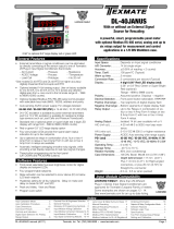
Functional Diagram
Pinout Diagram
The Top and Bottom View of the trnsmitter diagram shows the
transmitter with the relay configuration: Two 9 Amp Form C. An
analog output module is also shown as installed.
The TL Series Transmitter uses plug-in type screw terminal con-
nectors for all input and output connections. The power supply
connections (pins 14 and 15) have a unique plug and socket out-
line to prevent cross connection. The main board and input signal
conditioner use right-angled connectors as standard. The output
module uses straight-thru connectors as standard.
Auto-sensing AC/DC power supply. For voltages between
85-265 V AC / 95-300 V DC (PS1) or 15-48 V AC / 10-72 V DC (PS2).
!
WARNING: AC and DC input signals and power supply
voltages can be hazardous. Do Not connect live wires to
screw terminal plugs, and do not insert, remove or handle
screw terminal plugs with live wires connected.
Standard plug-in screw terminal connectors provided by Texmate:
Input Signal – Pins 1 to 6
Pins 1 to 6 are reserved for the input signal conditioner.
See the data sheet for the selected input signal conditioner.
Relay Output Pins- Pins 8 to 13
Pin 8-10 SP1 Normally Open
Pin 8-9 SP1 Normally Close
Pin 11-13 SP2 Normally Open
Pin 11-12 SP2 Normally Close
AC/DC Power Input- Pins 14 and 15
Auto-sensing AC/DC power supply. For voltages between
85-265 V AC/95-300 V DC (PS1) or 15-48 V AC/10-72 V DC (PS2).
Pin 14 AC/DC Neutral. Neutral power supply line.
Pin 15 AC/DC line. Live power supply line.
Analog Output- Pins 16 and 18
Pins 16 and 17 are the analog output pins on the optional
output module. Their pin definitions are:
Pin 16 Negative (–) analog output.
Pin 17 Positive (+) analog output.
Pin 18 Shield.
Connector PinoutsConnector Pinouts
AC/DC
POWER
+ – SHIELD
SP1 SP2
RELAYS
9A Form C
98 10 1211 1321 3 54 6 14
16 17 18
15
ANALOG
OUTPUT
ALL FIELD WIRE 90 ºC MIN.
See Leopard Family
Input Module

Texmate, Inc. Tel. (760) 598-9899 • www.texmate.comPage 8 TL_manual (d0007)
IA06: AC Volts True RMS, 300V AC
300D
IA10
: AC Millivolts, Scaled RMS,
10 0mV AC
ACI
HI
RANGE
ACmV
ACmV
HI
LO
LO
< Increase Span Decrease >
LEOPARD
LYNX
TIGER
Fully User Scalable
285A
IA09:
AC Amps Tr ue RMS, 1 Amp AC
IA11
:
AC Amps Tr ue RMS, 5 Amp AC
LEOPARD
LYNX
TIGER
1A/5A
Secondary
CT
Primary
AC Current
Fully User Scalable
++
+
AC AMPS RMS
1 A Shunt
301B
IA03: AC Milliamps Scaled RMS, 2/20/200mA AC
AC mA
AC mA
200mA
20mA
2mA
HI
LO
LEOPARD
LYNX
TIGER
280A
HI
RANGE
AC AMPS
HI
LO
LO
< Increase Span Decrease >
LEOPARD
LYNX
TIGER
1A
Secondary
CT
Primary
AC Current
Fully User Scalable
065F
IA04: AC AC Amps Scaled RMS, 1 Amp AC
IA05: AC AC Amps Scaled RMS, 5 Amp AC
ALL MODELS
Symbols Indicate Module Compatibility Within Meter Families
SOME MODELS MODEL SPECIFIC
TIGER Family
LEOPARD Family
LYNX Family
TIGER Family
LEOPARD Family
LYNX Family
TIGER Family
LEOPARD Family
LYNX Family
IA01: AC Volts Scaled RMS, 200/300V AC
Many additional input modules are available and others are constantly being developed. Check with your local distributor or www.texmate.
com for updated information.
Pre-calibrated I-Series input modules, that have span or zero potentiometers, can be interchanged between any I-Series compatible meter,
without recalibration, because all of the analog scaling and reference circuitry is self-contained within the module. Where appropriate, all the
standard ranges shown are designed to be header selectable by the user, and Texmate's unique SPAN ADJUST Header facilitates scaling
to almost any required engineering unit. See Input Module Component Glossary and Calibration on pages 13 and 14. Also see Two Point
Digital Calibration and Digital Calibration on page 4.
Unless otherwise specified Texmate will ship all modules pre-calibrated with factory preselected ranges and/or scalings as shown in BOLD
type. Other pre-calibrated standard ranges or custom ranges may be ordered. Factory installed custom scaling and other custom options
are also available (see Ordering Information, Special Options on last page).
WARNING: AC and DC input signals and power supply volt-
ages can be hazardous. Do Not insert, remove or handle modules
with live wires connected to any terminal plugs.
!
I-Series Input Signal Conditioning Modules

Texmate, Inc. Tel. (760) 598-9899 • www.texmate.com TL_manual (d0007) Page 9
IP01:
Process Loop,
4-20mA
IP02:
Process Loop, 4-20mA with 24VDC EXC
24V
External
Loop Supply
Common
Offset
0
+
_
Other devices can be
added to the loop.
< Decrease Zero Increase >
< Decrease Span Increase >
Range
HI
LO
OFF
ON
24V EXC
LEOPARD
LYNX
TIGER
Fully User Scalable
PIN 2
+_
091E
I-Series Input Signal Conditioning Modules
IP07: Universal Process Input
2V/5V/10V/20V/200V/2mA/20mA/Custom
224D

Texmate, Inc. Tel. (760) 598-9899 • www.texmate.comPage 10 TL_manual (d0007)
IS05:
Pressure/Load Cell 20/2mV/V, 5/10V Exc 4-wire
Pressure Transducer
or Load Cell 2
HI
LO
RANGE
mV/V
20
10V
5V
EXT
EXC
PRESSURE
LEOPARD
IS02
LYNX
TIGER
IS02
244C
IS06:
Pressure/Load Cell Ext Exc., 20/2mV/V, 4-wire
5 V or 10 V External Power
Supply Drift is Ratiometrically
Compensated by Module
For multiple pressure transducers
– +
2
HI
LO
RANGE
mV/V
20
10V
5V
EXT
EXC
PRESSURE
LEOPARD
IS04
LYNX
TIGER
IS04
244C
2
20
mV/V
10V
5V
4W
6W
EXC
Pressure Transducer
PRESSURE
LEOPARD
TIGER
IS01:
Strain Gage 5/10V DC Exc., 20/2mV/V, 4/6-wire
IS02:
Pressure/Load Cell
5/10V DC Exc., 20/2mV/V, 4/6-wire
151B
I-Series Input Signal Conditioning Modules
IS07:
Pressure/Load Cell Ext Exc. High Impedance,
20/2mV/V, 4/6–wire
External
Power
Supply 5V or 10V
For multiple pressure transducers
Exc
ZERO
Pressure Hi Impedance
10V
5V
2
20
mV/V
4W
6W
LEOPARD
TIGER
277A

Texmate, Inc. Tel. (760) 598-9899 • www.texmate.com TL_manual (d0007) Page 11
In addition to the analog calibration capabilities that enable many modules to
be interchanged between different meters without loss of accuracy the Leopard
Family of meters have enhanced Digital Calibration functions. See Page 4
ZERO ADJUST Header
When this header is provided, it works in conjunc-
tion with the ZERO OFFSET RANGE Header,
and expands the ZERO pot’s offset capability into
five equal negative steps or five equal positive
steps. This enables virtually any degree of input
signal offset required to display any desired engi-
neering unit of measure.
ZERO OFFSET RANGE Header
When provided, this three position header
increases the ZERO pot’s capability to offset the
input signal, to ±25% of the digital display span.
For example a Negative offset enables a 1 to 5V
input to display 0 to full scale. The user can select
negative offset, positive offset, or no offset (ZERO
pot disabled for two step non-interactive span and
offset calibration).
Basic standard range calibration of direct reading mod-
ules that utilize either Auto Zero or a ZERO pot, an
INPUT RANGE Header and or a SPAN pot.
1 If the module has an INPUT RANGE Header, reposition the
jumper clip to select the desired input signal range.
2. Apply a zero input or short the input pins. The display will auto
zero, or if the module has a ZERO pot, it should be adjusted until
the display reads zero.
3 Apply a known input signal that is at least 20% of the full scale
input range and adjust the SPAN pot until the display reads the
exact input value. For negative inputs, Leopard Family Meters
will display negative overrange at 50% of full scale range.
4 Decimal Points. The selection or positioning of decimal points
has no effect on the calibration of the modules
Wide range scaling, in engineering units not requiring off-
sets, with modules that utilize auto-zero or a ZERO pot, a
SPAN RANGE Header and or a SPAN ADJUST Header.
Texmate’s unique SPAN ADJUST and SPAN RANGE Headers
provide the circuit equivalent of an ultra-precision one megohm 75
or 150 turn potentiometer that can infinitely scale down any Input
Signal SPAN to provide any full scale Digital Display Span from
1999 (counts) to 001 (one count).
If the module has an INPUT RANGE Header, and the required full
Input Module Analog Calibration
LO RANGE HI RANGE
10%SPAN Pot %10% 10% 10% 10%
10%Signal Span %20% 30% 40% 50%
1
SPAN Adjust
Header position
Span Adjust Header Span Adjust Header
Span Range Header
2 3 4 5
10% 10% 10% 10% 10%
60% 70% 80% 90% 100%
1 2 3 4 5
< Decrease Span Increase >
12 345
< Decrease Span Increase >
12 345
Equivalent
Circuit
Acts like a
150 Tu rn
Potentiometer Low Range High Range
Input LO Input HI
HI
LO
< Increase Zero Decrease >
54 321
< Increase Zero Decrease >
5 4 32 1
Input and Output Pins
On most modules Pin 1 is the Signal High input
and Pin 3 is the Signal Low input. Typically Pin 2
is used for Excitation Voltage output.
HI
LO
24V
Exc
Offset
0
–
+
0
–
+
INPUT RANGE Header
Range values are marked on the PCB. Typically
two to four positions are provided, which are select-
ed with either a single or multiple jumper clip. When
provided, a custom range position is only functional
when the option has been factory installed.
Custom
200V
20V
2V
24V DC Output Header
On some modules this header enables a 24V
DC 25mA (max) Excitation/Auxiliary output to be
connected to Pin 2.
ON
OFF
OFF
ON
24V EXC
< Increase Span Decrease >
54 321
< Increase Span Decrease >
5 4 3 2 1
SPAN RANGE Header
When this header is provided it works in conjunc-
tion with the SPAN ADJUST Header by splitting its
adjustment range into a Hi and a Lo range. This
has the effect of dividing the adjustment range of
the SPAN pot into ten equal 10% steps across
100% of the input Signal Span.
Range
HI
LO
HI
LO
Zero Offset Range Header
0+–
–20%ZERO Pot %–20% –20% –20% –20%
No
Offset
NEGATIVE OFFSET POSITIVE OFFSET
–1200 or more countsOffset Range
+20% +20% +20% +20% +20%
+1200 or more counts
5
ZERO Adjust
Header position 4 3 2 1 1 2 3 4 5
75 Tu rn Potentiometer
–0
Equivalent
Circuit
< Increase Zero Decrease >
54 321
< Decrease Zero Increase >
12 345
75 Tu rn Potentiometer
+0
Zero Pot
Disabled
SPAN
Tu rn Clockwise to
Increase Reading
To the
Right Rear
SPAN Potentiometer (Pot)
If provided, the 15 turn SPAN pot is always on the
right side (as viewed from the rear of the meter).
Typical adjustment is 20% of the input signal
range.
20%SPAN Pot %20% 20% 20% 20%
20%Signal Span %40% 60% 80% 100%
1
SPAN Adjust
Header position 2 3 4 5
< Decrease Span Increase >
12 345
Acts like 75 Tu rn 1 Mega ohm Potentiometer
Input LO
Input
HI
Equivalent
Circuit
SPAN ADJUST Header
This unique five-position header expands the
adjustment range of the SPAN pot into five equal
20% steps, across 100% of the input Signal
Span. Any input Signal Span can then be pre-
cisely scaled down to provide any required Digital
Display span from 1999 counts to 001 (one count).
ZERO
Tu
rn Clockwise to
Increase Reading
To the
Left Rear
15 Tu rn Potentiometer
⊕ + 100 Counts⊕ – 100 Counts
–0+
ZERO Potentiometer (Pot)
If provided, the ZERO pot is always to the left
of the SPAN pot (as viewed from the rear of the
meter). Typically it enables the input signal to be
offset ±5% of full scale (-100 to +100 counts).
Zero Offset Range Header
0+–
No
Offset
NEGATIVE OFFSET
Decreases Digital Reading
POSITIVE OFFSET
Increases Digital Reading
15 Tu rn Potentiometer
–0
Equivalent
Circuit
15 Tu rn Potentiometer
+0
Zero Pot
Disabled
⊕ – 500 CountsOffset Range
– 100% of Offset
ZERO Pot%
⊕ + 500 Counts
+ 100% of Offset
Input Module Component Glossary

Texmate, Inc. Tel. (760) 598-9899 • www.texmate.comPage 12 TL_manual (d0007)
1
If the module has an INPUT RANGE Header the 2 V position should
be selected. This will provide a digital display of 1600 counts for an
input of 1.6 V which is (1.6 ÷ 4) = 40% of the examples 4 V signal
span. To scale down the Signal Span to 40% select the 40% Signal
Span position on the SPAN ADJUST Header (position 2).
2
If the module is a Process Input 1-5 V DC type, select the (Hi Range)
position on the SPAN RANGE Header and the 100%
Signal Span
position on the SPAN ADJUST Header
(position 5, max increase).
This will provide a digital display of 1600 counts for an input of 4V
which is 100% of the examples 4V Signal Span.
3 Set the ZERO OFFSET RANGE Header to the center position
(no offset). Apply 1 V and adjust the SPAN pot until the display
reads 400 . A 4V input would then read 1600 counts.
4 Set the ZERO OFFSET RANGE Header to the negative offset
position. If the module has a ZERO ADJUST Header select the
position that will provide a negative offset of ≈ –500 counts.
Apply 1 V and adjust the ZERO pot until the display reads
–100. Apply 5 V and check that the display reads 1500.
Example C: 4 to 20 mA to read 00.0 to +100.0%
Signal Span = 16 mA, Digital Display Span = 1000 counts.
1 The full scale Signal Span of the Process Input 4-20 mA modules
is 0 to 20 mA for a full scale Digital Display Span of 0 to 2000
counts. This will provide a digital display of 1000 counts with an
input of only 10 mA which is (10÷16)=62.5% of the examples 16
mA signal span.
2 To scale down the Signal Span to 62.5% select the (Hi Range)
Position on the Span Range Header and the 70% Signal Span
position on the SPAN ADJUST Header (position 2).
3 Set the ZERO OFFSET RANGE Header to the center position
(no offset). Apply 4 mA and adjust the SPAN pot until the display
reads 250 . A 16 mA input would then read 1000 counts.
4 Set the ZERO OFFSET RANGE Header to the positive offset
position. If the module has a ZERO ADJUST Header select
the position that will provide a negative offset of ≈ –250 counts.
Apply 4 mA and adjust the ZERO pot until the display reads 000.
Apply 20 mA and check that the display reads 1000. Select
decimal point XXX•X to display 00.0 to 100.0.
scale Digital Display Span (counts) is to be larger than the directly
measured value of the input Signal Span, then the next lower range
on the INPUT RANGE Header should be selected. The resulting over
range Signal Span is then scaled down, by selecting the position of the
SPAN RANGE Header and or the SPAN ADJUST Header, which will
reduce the input Signal Span to a percentage, that the required Digital
Display Span can be reached by calibration with the SPAN pot.
Example A: 0 to 10 V to read 0 to 1800 gallons.
Signal Span = 10V, Digital Display Span = 1800 counts
1 Select the 2 V INPUT RANGE Header position. This will provide
a digital display of 1800 counts with an input of only 1.8 V which
is (1.8÷10)=18% of the examples 10 V Signal Span.
2
To scale down the Signal Span to 18% select the 20% Signal Span
position on the SPAN ADJUST Header (position 1) or if the mod-
ule has a SPAN RANGE Header, select (LO Range) and 20%
Signal Span position on the SPAN ADJUST Header (position 2).
3 Apply a zero input or short the input pins. The display will auto
zero, or if the module has a ZERO pot, it should be adjusted until
the display reads zero.
4 Apply 10 V and adjust the SPAN pot until the display reads 1800.
Large offset scaling and calibration of process signal
inputs with modules that utilize ZERO ADJUST Headers
and or ZERO OFFSET RANGE Headers.
Texmate’s unique ZERO OFFSET RANGE Header enables the
use of a simple two step scaling and calibration procedure for those
process signals that require large offsets. This eliminates the back
and forth interaction, between zero and span settings, that is often
required to calibrate less finely engineered products.
The first step is to set the
ZERO OFFSET RANGE
Header to the
center position (No Offset) and scale down the Input Signal Span to
a percentage that will enable calibration with the SPAN pot to reach
the required Digital Display Span.
The second step is to set the ZERO ADJUST and or ZERO OFFSET
RANGE Header to provide a positive or negative offset of sufficient
counts that calibration with the ZERO pot will offset the Digital Display
Span to produce the required digital reading.
Example B: 1 to 5 V to read –100 to 1500 °C.
Signal Span = 4V, Digital Display Span = 1600 counts
Input Module Calibration Procedures Continued
Case Dimensions
22.5mm
(0.89”) 128.7mm
(5”)
102.4mm
(4”)
99.7mm
(3.9”)
SIDE
22.5 mm
(0.89”) TOP

Texmate, Inc. Tel. (760) 598-9899 • www.texmate.com TL_manual (d0007) Page 13
Installation Guidelines
Select Input Range and Analog Output
Installation
1. Install and wire transmitter per local applicable codes/
regulations, the particular application, and good instal-
lation practices.
2. Install transmitter in a location that does not exceed
the maximum operating temperature and that provides
good air circulation.
3. Separate input/output leads from power lines to pro-
tect the transmitter from external noise. Input/output
leads should be routed as far away as possible from
contactors, control relays, transformers and other noisy
components. Shielding cables for input/output leads is
recommended with shield connection to earth ground
near the meter preferred.
!
4. A circuit breaker or disconnect switch is required to
disconnect power to the meter. The breaker/switch
should be in close proximity to the meter and marked as
the disconnecting device for the meter or meter circuit.
The circuit breaker or wall switch must be rated for the
applied voltage (e.g., 120VAC or 240VAC) and current
appropriate for the electrical application (e.g., 15A or
20A).
5. See Connector Pinouts section for wiring.
6. Use 28-12 AWG wiring, minimum 90˚C (HH) tempera-
ture rating. Strip wire approximately 0.3 in. (7-8 mm).
7. Recommended torque on all terminal plug screws is
4.5 lb-in (0.51 N-m).
Quick Guide to Select Leopard TL Series Transmitters'
Input Range and Analog Output Type
E469078
Texmate, Inc. Tel. (760) 598-9899 • www.texmate.com
V mA
A. Remove the four screws from the top panel
(the label side), nuts are on the bottom side.
C. 1. Lift up Analog Ouput Board
2. Move the jumper to select 4-20 mA
or 0 to 10 V
3. Insert the board back to the main board B. Move jumper to select Input Range
for applicable input modules (see Input
module suppliment z87 on our website.)
(Goo1)

Texmate, Inc. Tel. (760) 598-9899 • www.texmate.comPage 14 TL_manual (d0007)
Ordering Information
WARRANTY
Texmate warrants that its products are free from defects in material and workmanship under
normal use and service for a period of one year from date of shipment. Texmate’s obligations
under this warranty are limited to replacement or repair, at its option, at its factory, of any of
the products which shall, within the applicable period after shipment, be returned to Texmate’s
facility, transportation charges pre-paid, and which are, after examination, disclosed to the sat-
isfaction of Texmate to be thus defective. The warranty shall not apply to any equipment which
shall have been repaired or altered, except by Texmate, or which shall have been subjected
to misuse, negligence, or accident. In no case shall Texmate’s liability exceed the original pur-
chase price. The aforementioned provisions do not extend the original warranty period of any
product which has been either repaired or replaced by Texmate.
USER’S RESPONSIBILITY
We are pleased to offer suggestions on the use of our various products either by way of printed
matter or through direct contact with our sales/application engineering staff. However, since
we have no control over the use of our products once they are shipped, NO WARRANTY
WHETHER OF MERCHANTABILITY, FITNESS FOR PURPOSE, OR OTHERWISE is made
beyond the repair, replacement, or refund of purchase price at the sole discretion of Texmate.
Users shall determine the suitability of the product for the intended application before using,
and the users assume all risk and liability whatsoever in connection therewith, regardless
of any of our suggestions or statements as to application or construction. In no event shall
Texmate’s liability, in law or otherwise, be in excess of the purchase price of the product.
Texmate cannot assume responsibility for any circuitry described. No circuit patent or software
licenses are implied. Texmate reserves the right to change circuitry, operating software, speci-
fications, and prices without notice at any time.
TL .......
Standard Leopard Series Transmitter and Controller
4POWER SUPPLY
PS1 ...... 85-265VAC/95-300VDC
PS2 .....15-48VAC/10-72VDC
4INPUT MODULES
Unless otherwise specified Texmate will ship all modules precali-
brated with factory preselected ranges and/or scalings as shown
in
BOLD
type
IA01 ..AC-Volts Scaled RMS, 200/300V AC
IA02 ..AC-Volts Scaled RMS, 200mV/2V/20V AC
IA03 ..AC-mA Scaled RMS, 2/20/200mA AC
IA04 ..AC-Amps Scaled RMS, 0-1 Amp AC (0-100.00)
IA05 ..AC-Amps Scaled RMS, 0-5 Amp AC (0-100.00)
IA06 ..AC-Volts True RMS, 200/300V AC
IA07 ..AC-Volts True RMS, 200mV/2V/20V AC
IA08 ..AC-mA True RMS, 2/20/200mA AC
IA09 ..AC-Amps True RMS, 0-1 Amp AC (0-100.00)
IA10 ..AC-Millivolt, Scaled RMS, 100mV AC
IA11 ..AC-Amps True RMS, 0-5 Amp AC (0-100.00)
IA12 ..AC-Millivolt, True RMS, 100mV AC
ID01 ..DC-Volts, 2/20/200V/Custom w/24V DC Exc
ID02 ..DC-Millivolt, 20/50/100/200mV DC w/24V DC Exc
ID03 ..DC-Milliamp, 2/20/200mA DC w/24V DC Exc
ID04 ..DC-Amps, 5A DC
ID05 ..DC-Volts 2/20/200/Custom V DC w/Offset and 24V Exc. .
ID07 ..DC-Milliamp, 2/20/200mA DC w/Offset and 24V Exc ....
ID09 ..DC-Amps, 1A DC
IP01 ..Process Loop, 4-20mA(0-100.00)
IP02 ..Process Loop, 4-20mA(0-100.00) w/24VDC Exc
IP03 ..Process Input, 1-5V DC(0-100.00) w/Offset, 24V Exc
IP07 ..
Universal Process 2V/5V/10V/20V/200V/2mA/20mA/Custom
IR02 ..3-Wire Potentiometer 1KΩ min (0-F.S.)
IR03 ..Linear Potentiometer, 3-wire, 1KΩ min
IR05 ..Resistance 2KΩ
IS01 ..Strain Gage 5/10VDC Exc., 20/2mV/V, 4/6-wire
IS02 ..Pressure 5/10VDC Exc., 20/2mV/V, 4/6-wire
IS04 ..Pressure Ext Exc., 20/2mV/V, 4/6–wire
IS05 ..Pressure/Load Cell 20/2mV/V, 5/10V Exc 4-wire
IS06 ..Pressure/Load Cell Ext Exc., 20/2mV/V, 4-wire
IS07 ..
Pressure 20/2mV/V with High Impedance and External Excitation
4
ANALOG OUTPUT
OIC .. Isolated 16 Bit Current Output, 4-20mA
OIV .. Isolated 16 Bit Voltage Output, 0-10VDC
4
RELAY OUTPUT
R11 .. Single 9A Form C Relay
R12 .. Dual 9A Form C Relays
4SPECIAL OPTIONS
Range Change and Custom Scaling
Customer must specify the input signal range or digital span and
the desired display range, or output signal range. Multiple inputs or
multiple displays require a separate range change or custom scaling
part number and a specified channel for each input or display.
Range Change
and calibration to another header selectable standard range
CR-CHANGE ... Range Change from Standard Range shown in BOLD type
Output - Custom Scaling
within standard ranges of analog output.
COA-3/3.5/4 ...Custom scaling of analog output
Short Depth 96x48 Remote Display/Programmer
OP-TL/RDISP ..Remote Display/Programmer w/Cable
and Belt Clip Carrying Case
4BASE MODEL NUMBER
SPECIAL OPTIONS
BASE MODEL #
POWER SUPPLY INPUT MODULES ANALOG OUTPUT RELAY OUTPUT
OA____
* Selection
Required * * * *
For product details visit www.texmate.com
Local Distributor Address
450 State Place • Escondido, CA 92029
Tel: 1-760-598-9899 • USA 1-800-839-6283 • That’s 1-800-TEXMATE
Fax: 1-760-598-9828 • Email: [email protected] • Web: www.texmate.com
Copyright © 2017 Texmate Inc. All Right Reserved.
/