Page is loading ...

IA09-11 Data Sheet (NZ339) Page 1Texmate, Inc. Tel. (760) 598-9899 • www.texmate.com
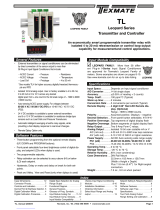
AC AMPS TRUE RMS 1 OR 5 AMP MODULE
Input
Connected to Isolated
Current Transformer.
Span Adjust Header.
Provides fine full scale
range adjustment.
Interface to
Lynx, Leopard and Tiger
Families
State-of-the-Art
Electromagnetic Noise Suppression.
Circuitry ensures signal integrity
even in harsh EMC environments.
High Precision 1 or 5 Amp
Shunt Resistor.
Improved linearity.
Hardware Module Specifications
Current Range (Isolated) IA09: 0-1 A AC, IA11: 0-5 A AC. 0.02 % linearity on both.
Frequency Range 0.2 Hz to 10 KHz (3 dB).
Resolution 1 mA over full scale input.
Accuracy
Lynx 0.03 % of full scale input ± 2 digit.
Leopard 0.05 % of full scale input ± 2 digit.
Tiger 0.02 % of full scale input ± 1 digit.
Output Signal Adjustable to 2 V full scale using on-board trimmer and
header selections.
Forced Zero Forces output to 0000 if below 1 % of full scale.
Meter Interface Can be utilized in the Lynx, Leopard, and Tiger
range of indicators, meter relays, and controllers.
Span Drift ± 500 ppm /°C of full scale maximum.
Some Relevant Operating System Features
Direct display of true RMS current.
Setpoint control (Tiger & Leopard).
Full scale calibration accurate for any sized signal.
This revolutionary module utilizes the Texmate designed ∆∑ RMS-to-DC convertor circuit block. This circuit
block provides true RMS measurements over a wide range of isolated input currents while maintaining
excellent linearity up to a 10 kHz waveform frequency.
At last, the answer to precise and repeatable RMS current measurements for the AC power industry.
Fits Lynx Leopard & Tiger 320 Series
Texmate Patented ∆∑
RMS-to-DC Converter.
High accuracy, extremely linear.
Active Bandpass Filter.
0.2 Hz to 10 kHz bandwidth.
High Accuracy
Amps AC
Tr m s
INPUTS
Span Potentiometer.
Provides precise full scale
adjustment.
Span Range Header.
Provides Coarse
range adjustment.
IA09 (1 Amp)
IA11 (5 Amp)
Input Module
Order Code Suffix

Texmate, Inc. Tel. (760) 598-9899 • www.texmate.comPage 2 IA09-11 Data Sheet (NZ339)
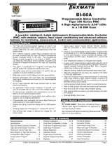
Connector Pinouts
Introduction
301B
1
2
I in +
I in -
Current Input
5 A
Secondary
CT
Load
N L
Note:
The IA09 and IA11 input module
has been designed for use with an
isolating current transformer (CT).
IA11 wired to monitor RMS amps usa
g
e on a resistiv
e
load connected to a single phase mains supply
Figure 1 – IA09/IA11 Input Module Component La yout
The AC amps true RMS input module is a universal module designed to function with the Lynx,
Leopard, and Tiger r ange of indicators , meter rela ys, and prog rammable meter controllers
(PMCs).
IA09 has a 1 amp high-precision shunt resistor installed f or an isolated current r ange of 0 to 1
amp, while IA11 has a 5 amp high-precision shunt resistor installed for an isolated current range
of 0 to 5 amps . A span potentiometer, span adjust header, and a span range header are used
to adjust the input signal full scale . A zero input current produces a 0 V output signal, meaning
no zero adjustment is necessar y.
Tiger Controllers and Leopard Meter Relays
The Tiger and Leopard range use internal software functions to calibrate the span. However, it
may be necessar y to adjust the span potentiometer to br ing the maxim um input signal within
the full scale range of the instrument.
1 A Shunt for IA09
5 A Shunt for IA11
to decrease readin
g
301B
2
HI
L
OW
When the input signal is be yond
the full scale range of a Tiger con-
troller, the display flashes [OVER].
When the input signal is be yond
the full scale r ange of a Leopard
meter, the top segment of each
digit of the display flashes.
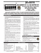
Figure 2 – Span Potentiometer Adjustment
Lynx Indicators
Calibration settings on all L ynx indicators are carr ied out using the b uilt-in headers and span
potentiometer. The 15 turn span potentiometer has an approximate span adjustment of 20% of
the full scale signal. Together, the span r ange header and the span adjust header e xpand the
range of the span potentiometer into 10 equal adjustab le portions, each por tion being 10% of
the full scale range.
When the input signal is be yond the full scale range of a Lynx indicator, a 1 is displayed in the
most significant digit with all other digits b lank.
With the span range header set to HI and the span adjust header set to 100%, turn the 15 turn
span potentiometer counter-clockwise to decrease the signal until a reading appears on the dis-
play (See Figure 2). Now calibrate the instrument using the software calibration method for your
instrument.

IA09-11 Data Sheet (NZ339) Page 3Texmate, Inc. Tel. (760) 598-9899 • www.texmate.com
Header Descriptions
Span Range Header
The span r ange header w orks together with the span
adjust header b y splitting its adjustment r ange into a
high and a low range. This has the eff ect of dividing
the adjustment r ange of the span potentiometer into
ten equal 10% sectors across 100% of the input signal
span (See Figures 6 and 7).
LOW RANGE HI RANGE
10%Span Pot % 10% 10% 10% 10%
10%Signal Span % 20% 30% 40% 50%
1
Span Adjust
Header position
Span Adjust Header Span Adjust Header
Span Range Header
2 3 4 5
10% 10% 10% 10% 10%
60% 70% 80% 90% 100%
1 2 3 4 5
12 3 4 512 3 4 5
Equivalent
Circuit
Acts like a 150 turn, 1 megohm potentiometer
Low Range High Range
HI
LOW
Input
Signal
Low
Input
Signal
High
Span
Pot
100% 20%
100% 20%
SPAN Turn clockwise to
increase reading
Viewed from
the right-hand
rear of meter
100% 20%
54 3 21
100% 20%
Header Positions
Range
HI
LOW
HI
LOW
Span Potentiometer (Pot)
The 15 tur n span potentiometer is located on the r ight-hand
side of the input module (when vie wed from the rear of the
meter). Typical adjustment is 20% of the input signal r ange
(See Figure 3).
20%Span Pot % 20% 20% 20% 20%
20%Signal Span % 40% 60% 80% 100%
1
Span Adjust
Header position 2 3 4 5
12 3 4 5
Acts like a 75 turn, 1 megohm potentiometer
Input
Signal
Low
Input
Signal
High
Equivalent
Circuit
Span
Pot
100% 20%
Span Adjust Header
This unique fiv e-position header e xpands the adjust-
ment r ange of the span potentiometer into fiv e equal
20% sectors, across 100% of the input signal span. Any
input signal span can then be precisely scaled do wn to
provide any required display span from full scale to the
smallest viewable unit (See Figures 4 and 5).
Figure 3 – Span Pot
Figure 4 – Span Adjust Header
Figure 5 – Span Adjust Header Operation
Figure 6 – Span Range Header
Figure 7 – Span Range Header Operation

Texmate, Inc. Tel. (760) 598-9899 • www.texmate.comPage 4 IA09-11 Data Sheet (NZ339)
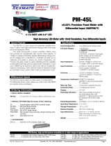
1) The first adjustment to mak e is the
coarse r ange setting. Set the span
range header to the LO W position
(See Figure 8).
This effectively halves the maximum
counts of the DX-35 from 1999 to
1000 (+ or – 20% of 1999.This could
be as much as 400 counts).
Lynx Indicator Calibration Setup
To successfully calibrate a Lynx indicator over the input signal span with an IA09 or IA11 input module installed, the headers must be
correctly set and the span pot adjusted to the final displa y setting.
Example
With an IA11 input module installed in a DX-35 L ynx indicator, we want to show a digital representation of a 5 A input signal o n the
display. As the DX-35 has a maximum of 1999 counts, 5 A could easily be shown to two decimal places by setting the span setting to
500 counts.
To configure the input module to sho w 500 counts for an isolated input signal of 5 A, proceed as f ollows:
301B
2
L
OW
Span Ran
g
e Header
moved to LOW positio
n
3) The final adjustment can no w be made
using the span pot (See Figure 10).
As the display reading is below the required
setting of 500 counts , tur n the span pot
clockwise to increase the counts until the
display shows a reading of 500 counts.
2) The next adjustment is the fine r ange
setting. Set the span adjust header to
the 40% position (See Figure 9).
This position should lea ve you with a
display setting lower than 500 counts .
By ho w much, depends on the posi-
tion of the span pot.
301B
2
HI
L
OW
Span Ad
j
ust Heade
r
moved to 40% position
301B
2
HI
L
OW
Turn span pot clockwis
e
to decrease display readin
g
B
Figure 8 – Span Range Header
Adjustment
Figure 9 – Span Adjust Header
Adjustment
Figure 10 – Span Pot Adjustment
WARRANTY
Texmate warrants that its products are free from def ects in mater ial and w orkmanship under
normal use and ser vice for a per iod of one y ear from date of shipment. Texmate’s obligations
under this warranty are limited to replacement or repair, at its option, at its factory, of any of the
products which shall, within the applicable period after shipment, be returned to Texmate’s facil-
ity, tr ansportation charges pre-paid, and which are , after e xamination, disclosed to the satis-
faction of Texmate to be thus def ective. The warranty shall not apply to an y equipment which
shall have been repaired or altered, except by Texmate, or which shall have been subjected to
misuse, negligence , or accident. In no case shall Texmate’s liability e xceed the or iginal pur-
chase price. The aforementioned provisions do not e xtend the or iginal warranty period of any
product which has been either repaired or replaced b y Texmate.
USER’S RESPONSIBILITY
We are pleased to offer suggestions on the use of our v arious products either by way of print-
ed matter or through direct contact with our sales/application engineering staff. However, since
we ha ve no control o ver the use of our products once the y are shipped, NO WARRANTY
WHETHER OF MERCHANT ABILITY, FITNESS FOR PURPOSE, OR O THERWISE is made
beyond the repair, replacement, or refund of purchase pr ice at the sole discretion of Texmate.
Users shall deter mine the suitability of the product f or the intended application bef ore using,
and the users assume all risk and liability whatsoever in connection therewith, regardless of any
of our suggestions or statements as to application or constr uction. In no event shall Texmate’s
liability, in law or otherwise, be in excess of the purchase pr ice of the product.
Texmate cannot assume responsibility for any circuitry described. No circuit patent or software
licenses are implied. Texmate reserves the right to change circuitry, operating software, speci-
fications, and prices without notice at any time.
Tel: 1-760-598-9899 • USA 1-800-839-6283 • That’s 1-800-TEXMATE
1934 Kellogg Ave. • Carlsbad, CA 92008
Email: [email protected] • Web: www.texmate.com
/