Page is loading ...

Pura
Advanced Online Hygrometer
User’s Manual
°Cdp
°Fdp
Pura
Advanced Online
Setup
97074 Issue 9
March 2013

Please ll out the form(s) below for each instrument that has been purchased.
Use this information when contacting Michell Instruments for service purposes.
Instrument
Code
Serial Number
Invoice Date
Location of Instrument
Tag No
Instrument
Code
Serial Number
Invoice Date
Location of Instrument
Tag No
Instrument
Code
Serial Number
Invoice Date
Location of Instrument
Tag No

© 2013 Michell Instruments
This document is the property of Michell Instruments Ltd. and may not be copied or
otherwise reproduced, communicated in any way to third parties, nor stored in any Data
Processing System without the express written authorization of Michell Instruments Ltd.
Pura Advanced Online Hygrometer
For Michell Instruments' contact information please go to
www.michell.com
°Cdp
°Fdp
Pura
Advanced Online
Setup

Pura Advanced Online Hygrometer User’s Manual
iv 97074 Issue 9, March 2013
Contents
Safety ................................................................................................................................vi
Electrical Safety ...........................................................................................................vi
Pressure Safety ............................................................................................................vi
Toxic Materials .............................................................................................................vi
Repair and Maintenance ...............................................................................................vi
Calibration ...................................................................................................................vi
Safety Conformity ........................................................................................................vi
Abbreviations .....................................................................................................................vii
Warnings ...........................................................................................................................vii
1 INTRODUCTION ................................................................................................1
1.1 Features ............................................................................................................ 1
2 INSTALLATION ..................................................................................................2
2.1 Unpacking the Instrument ................................................................................... 2
2.1.1 Unpacking Pura Advanced Online Hygrometer ................................................. 2
2.1.2 Unpacking Pura SEN (transmitter, no block version) ......................................... 3
2.1.3 Unpacking Pura OEM-single bag, PRM-double bag versions .............................. 4
2.1.4 Unpacking Monitor ........................................................................................ 4
2.1.5 Accessories Pack (Pura SEN, OEM, PRM) ........................................................ 5
2.2 Pura Advanced Online Components ...................................................................... 5
2.3 Pura SEN ........................................................................................................... 6
2.4 Pura OEM, PRM .................................................................................................. 6
2.5 Monitor .............................................................................................................. 7
2.6 Monitor Panel Layout .......................................................................................... 7
2.7 Transmitter Mounting ......................................................................................... 8
2.7.1 Direct Pipeline Connection ............................................................................. 8
2.7.2 Sensor Block Connection ............................................................................... 9
2.7.3 Pura OEM & PRM Connection ....................................................................... 10
2.8 Preparation of the Cable ................................................................................... 11
2.8.1 Wiring Connection Between the Transmitter and the Monitor .......................... 12
2.9 Mounting the Monitor ....................................................................................... 13
2.10 Electrical Connections ....................................................................................... 14
2.10.1 High Voltage Power Supply Input ................................................................. 14
2.10.2 Low Voltage Power Supply Input (Optional) .................................................. 15
2.11 Pressure Transducer Connection (Optional) ........................................................ 15
2.12 Transmitter Connections .................................................................................... 16
2.13 Transmitter Installation ..................................................................................... 16
3 OPERATION ....................................................................................................17
3.1 Set-Up Security Feature .................................................................................... 17
3.1.1 Selecting the Engineering Units .................................................................... 18
3.1.2 Changing the Setpoint Values ..................................................................... 18
3.1.3 Hysteresis, Make/Break Delay & Delay Type .................................................. 19
3.1.4 Analog Output Scaling ................................................................................ 20
3.1.5 Display Brightness Adjustment ..................................................................... 20
3.2 Pressure Compensation ..................................................................................... 21
3.3 Using a Pressure Transducer ............................................................................. 21
3.3.1 Manual Pressure Input Calibration ................................................................ 21
3.3.2 Automatic Pressure Input Calibration ............................................................ 22
3.4 Using a Fixed Pressure Input in Single Channel Mode .......................................... 22
4 MAINTENANCE ................................................................................................23
4.1 Fault Conditions ............................................................................................... 23

Pura Advanced Online Hygrometer User’s Manual
Michell Instruments v
Figures
Figure 1 Unpacking - Monitor and Pura SEN, no block version .....................................2
Figure 2 Unpacking - Monitor and Pura OEM / PRM ....................................................3
Figure 3 Unpacking - Pura SEN - Transmitter, No Block ...............................................3
Figure 4 Unpacking - Pura OEM & PRM - Single / Double Bag .....................................4
Figure 5 Unpacking - Monitor ...................................................................................4
Figure 6 Unpacking - Accessories Pack ......................................................................5
Figure 7 Components ...............................................................................................5
Figure 8 Pura SEN ...................................................................................................6
Figure 9 Pura OEM, PRM ..........................................................................................6
Figure 10 Control Layout and Functions ......................................................................7
Figure 11 Sensor Block Connection .............................................................................9
Figure 12 Connector Terminal Block Removal ............................................................11
Figure 13 Cable Connections ....................................................................................12
Figure 14 Connector Installation ...............................................................................12
Figure 15 Mounting the Monitor ...............................................................................13
Figure 16 High Voltage Power Supply Connections .....................................................14
Figure 17 Low Voltage Power Supply Connections ......................................................15
Figure 18 Electrical Connection Detail .......................................................................15
Figure 19 Transmitter Connections............................................................................16
Figure 20 Location of the Lockout switches ...............................................................17
Figure 21 Pura SEN .................................................................................................26
Figure 22 Pura PRM & OEM ......................................................................................26
Figure 23 Monitor Dimensions ..................................................................................27
Appendices
Appendix A Technical Specications .............................................................................. 25
Appendix B Setup Codes .............................................................................................29
Appendix C EC Declaration of Conformity ......................................................................32
Appendix D Quality, Recycling & Warranty Information ...................................................34
D.1 Recycling Policy ...........................................................................34
D.2 WEEE And RoHS Compliance ........................................................ 34
D.3 Manufacturing Quality .................................................................. 34
D.4 Calibration Facilities .....................................................................35
D.5 Return Policy ...............................................................................35
D.6 Warranty .....................................................................................35
Appendix E Return Document & Decontamination Declaration ........................................ 37
Tables
Table 1 Cable Connections ..................................................................................... 12
Table 2 Operation Access Levels ............................................................................. 17
Table 3 Engineering Unit Selection .........................................................................18

Pura Advanced Online Hygrometer User’s Manual
vi 97074 Issue 9, March 2013
Safety
The manufacturer has designed this equipment to be safe when operated using the procedures
detailed in this manual. The user must not use this equipment for any other purpose than that
stated. Do not apply values greater than the maximum value stated.
This manual contains operating and safety instructions, which must be followed to ensure the safe
operation and to maintain the equipment in a safe condition. The safety instructions are either
warnings or cautions issued to protect the user and the equipment from injury or damage. Use
competent personnel using good engineering practice for all procedures in this manual.
Electrical Safety
The instrument is designed to be completely safe when used with options and accessories supplied
by the manufacturer for use with the instrument.
Pressure Safety
DO NOT permit pressures greater than the safe working pressure to be applied to the instrument.
The specied safe working pressure is 24 MPa (240 barg / 3480 psig).
Toxic Materials
The use of hazardous materials in the construction of this instrument has been minimized. During
normal operation it is not possible for the user to come into contact with any hazardous substance
which might be employed in the construction of the instrument. Care should, however, be exercised
during maintenance and the disposal of certain parts.
Repair and Maintenance
The instrument must be maintained either by the manufacturer or an accredited service agent. For
contact information visit the website at www.michell.com
Calibration
Periodic re-calibration is recommended in order to maintain the highest quality of measurement in
your application. Michell Instruments recommends that you have your Pura transmitter re-calibrated
annually unless it is used in a mission-critical application or in a contaminated environment, in which
case the calibration interval should be reduced accordingly.
Michell Instruments can offer a variety of re-calibration and exchange transmitter schemes to suit
your specic needs. A local representative will be pleased to provide detailed, custom advice.
Safety Conformity
This product meets the essential protection requirements of the relevant EU directives. Further
details of applied standards may be found in Appendix D.

Pura Advanced Online Hygrometer User’s Manual
Michell Instruments vii
Abbreviations
The following abbreviations are used in this manual:
barg bar gauge
°C degrees Celsius
°F degrees Fahrenheit
dp dew point
DC direct current
μm micro-meter
lbf-ft pound foot
l/min liters per minute
mA milliampere
Mpa megapascal
m/sec meters per second
mW milliwatts
nF nano-Farad
Nm Newton meter
ppmV parts per million by volume
RH relative humidity
scfh standard cubic feet per hour
scfs standard cubic feet per second
V volts
Ω ohms
Warnings
The following general warning is applicable to this instrument. It is repeated in the text
in the appropriate locations.
!
Where this hazard warning symbol appears in the following
sections it is used to indicate areas where potentially hazardous
operations need to be carried out.
Where this symbol appears in the following sections it is
used to indicate areas of potential risk of electric shock.

Pura Advanced Online Hygrometer User’s Manual
viii 97074 Issue 9, March 2013
This page left intentionally blank

Pura Advanced Online Hygrometer User’s Manual
Michell Instruments 1
INTRODUCTION
1 INTRODUCTION
The Pura Advanced Online dew-point hygrometer is an instrument designed for the
continuous online measurement of moisture content in non-corrosive gases, over an
operational range of -120 to -40°C (-184 to -40°F) dew point and equivalent units (see
Technical Specications, Appendix A).
The system comprises a programmable monitor congured to accept a unique Michell
data string from the Pura transmitter. The zero and span of the monitor are set to cover
the dew-point range -120 to -40°Cdp (-184 to -40°Fdp) at operating pressures up to 24
MPa (240 barg / 3480 psig).
Two alarm outputs are provided for connection to external systems which are user-
congurable both in terms of setpoint and operating mode. Current output is standard
and factory set at 4-20 mA (or optionally set at 0-20 mA or 0-10 V).
The monitor has a pressure input channel for any industry standard 2-wire pressure
transmitter. In addition to providing a pressure measurement, the pressure signal can
be used to provide real-time pressure compensation on the primary channel when
displaying ppm values. The customer can also set a xed pressure compensation value.
The pressure input only affects the ppmV or ppbV units. For dew point, the displayed
value is a pressure dew point.
1.1 Features
The Pura Advanced Online Hygrometer is simple to use and install, and can be congured
to meet specic needs.
• ¼” male VCR process connections for PRM and OEM version
½” male VCR process connection for Pura SEN version
• Dew-point, ppmV or ppbV moisture content
• 4-wire connection - digital string signal
• Sensor block compliant with clean room standards
• Measurement range -120 to -40°C (-184 to -40°Fdp)
• Up to ±1°C dp accuracy
• Calibration certicate (NPL, NIST)

Pura Advanced Online Hygrometer User’s Manual
2 97074 Issue 9, March 2013
INstallatIoN
2 INSTALLATION
!
It is essential that the connection of electrical and gas supplies
to this instrument be undertaken by competent personnel.
2.1 Unpacking the Instrument
2.1.1 Unpacking Pura Advanced Online Hygrometer
The Pura Advanced Hygrometer instrument and accessories are packed in a box and the
method of unpacking is shown as follows:
Figure 1
Unpacking - Monitor and Pura SEN, no block version

Pura Advanced Online Hygrometer User’s Manual
Michell Instruments 3
INstallatIoN
Figure 2
Unpacking - Monitor and Pura OEM / PRM
2.1.2 Unpacking Pura SEN (transmitter, no block version)
Unpack the dew-point transmitter box as follows:
Figure 3
Unpacking - Pura SEN - Transmitter, No Block
NOTE: The transmitter sensing element is protected while in transit by a red
cover containing a small desiccant capsule. The connection pins are protected
by a red plastic cap. None of these plastic items are required for the operation
of the transmitter.
NOTE: Keep the connector in a safe place until the transmitter is ready for
wiring.

Pura Advanced Online Hygrometer User’s Manual
4 97074 Issue 9, March 2013
INstallatIoN
2.1.3 Unpacking Pura OEM-single bag, PRM-double bag versions
Figure 4
Unpacking - Pura OEM & PRM - Single / Double Bag
2.1.4 Unpacking Monitor
The monitor (2) is packed, together with its xing clamps (1) as shown below.
1
°Cdp
°Fdp
Pura
Advanced Online
Setup
2
Figure 5
Unpacking - Monitor

Pura Advanced Online Hygrometer User’s Manual
Michell Instruments 5
INstallatIoN
2.1.5 Accessories Pack (Pura SEN, OEM, PRM)
The accessories pack is shown below:
1
2
3
Figure 6
Unpacking - Accessories Pack
2.2 Pura Advanced Online Components
On delivery, please check that all the following standard components are present in the
packing box. Report any shortages immediately.
2
3
Pura
Advanced Online Hygrometer
User’s Manual
Pura
Advanced Online
©
©
Setup
97074 Issue 9
March 2013
1
4
5
7
8
°Cdp
°Fdp
Pura
Advanced Online
Setup
6
Figure 7
Components
1. PURA Monitor
2. Clamps
3. Sensor cable assembly
4. Pura Transmitter (SEN) OR
Pura Transmitter (OEM) or (PRM)
Leak test certicate included
5. Screwdriver
6. Power cable
7. User’s manual
8. Calibration certicate

Pura Advanced Online Hygrometer User’s Manual
6 97074 Issue 9, March 2013
INstallatIoN
2.3 Pura SEN
NOTE: For environmental and operating conditions, refer to Appendix A,
Technical Specications.
Electrical connector
Transmitter cover
Transmitter label
Hexagonal nut
Process connection
Sensing element
Figure 8
Pura SEN
2.4 Pura OEM, PRM
NOTE: For environmental and operating conditions, refer to Appendix A,
Technical Specications.
NOTE: OEM and PRM version transmitters are protected in transit by putting
in a plastic bag lled with nitrogen. Pura OEM transmitter has single bag
protection, Pura PRM transmitter has double bag protection.
Electrical connector
Transmitter cover
Transmitter label
Sensor block
Gas inlet
(see note below) Gas outlet
NOTE: The Pura has a uni-directional connection and must be
connected so the upstream ow is connected to the inlet port
of the Pura block (marked with a silver label).
INLET
Figure 9
Pura OEM, PRM

Pura Advanced Online Hygrometer User’s Manual
Michell Instruments 7
INstallatIoN
2.5 Monitor
The instrument has a 5-digit display, set-up on delivery to display a dew-point temperature
range of -120° to -40°Cdp (-40° to -184°Fdp).
Dew-point temperature units are displayed by the last LED located to the far right of
the display. On delivery, °Cdp is set-up. If required, the units can be changed to °F. The
method of conguring the unit for °F is described in Section 3.1.1.
Optionally, the instrument can be set-up to read dew point in parts per million ppmV or
parts per billion ppbV. This option requires the hygrometer to be set-up for ppmV or ppbV
(see Section 3.1.1).
Four dew-point temperature alarm indications are provided by four LEDs located on the
bottom of the display. These are marked SP1, SP2, SP3, SP4. Access to the alarm relay
contacts is provided on the rear panel. The connection for these alarm relay contacts
is shown in
Figure 18
. NOTE: Every display is factory tted with 2 alarm relays
as standard.
The operating temperature at which these alarm outputs operate is set-up as shown in
Section 3.1.2.
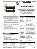
2.6 Monitor Panel Layout
Figure 10
shows the layout of these controls and their respective operational functions.
Pura
Advanced Online
Setup
1
2
3
4
1Increases the value of the displayed parameter; moves through each
displayed parameter
2Increases the value of the displayed parameter; moves through each
displayed parameter
3 LED annunciations for Setpoints 1 - 4
4Saves programming settings, moves between programming steps
Figure 10
Control Layout and Functions

Pura Advanced Online Hygrometer User’s Manual
8 97074 Issue 9, March 2013
INstallatIoN
2.7 Transmitter Mounting
2.7.1 Direct Pipeline Connection
The transmitter may be directly mounted into a pipe or duct
.
!
CAUTION: Do not mount the transmitter too close to the
bottom of a bend where any condensate in the pipeline might
collect and saturate the probe.
The pipe or duct will require a 1/2” VCR male process connection thread to match the
transmitter body thread. For circular pipework, to ensure the integrity of a gas tight
seal, a mounting ange will be required on the pipework in order to provide a at
surface to seal against.
Procedure
!
The following procedure must be carried out by competent
personnel.
1. Ensure that the red protective cover has been removed from the
tip of the transmitter.
!
WARNING: Under no circumstances should the lter guard be
handled with the ngers.
2. After rst checking that the pipeline has a wide enough bore to
accept the transmitter’s process connection screw the transmitter
into the pipe. Tighten enough to obtain a gas tight seal. (Torque
will depend upon the pipeline material.)
Michell Instruments recommends the use of Swagelok® retained gasket assemblies,
containing silver plated, stainless steel 1/2” VCR gaskets, when connecting the Pura
into a gas line.
NOTE: Do not overtighten or the thread on the pipework may be stripped.

Pura Advanced Online Hygrometer User’s Manual
Michell Instruments 9
INstallatIoN
2.7.2 Sensor Block Connection
!
The following procedure must be carried out by a qualied
installation engineer.
To mount the transmitter into the sensor block (preferred method), proceed as follows,
refer to
Figure 11.
1. Remove the red protective cover (2) from the tip of the transmitter
(1).
2. Fit the 1/2” VCR gasket (3) over the threaded part of the transmitter
body.
!
WARNING: Under no circumstances should the lter guard be
handled with the ngers.
3. Screw the transmitter (1) into the sensor block (4) and tighten the
gas line nut 1/8 (one eighth) of a turn using a second spanner/
wrench. NOTE: Use the ats of the hexagonal nut and not
the sensor body.
4. Fit the transmitter cable/connector assembly to the plug located
on the base of the transmitter and tighten the xing screw (see
Figure 14).
P
u
r
a
T
r
a
n
s
m
i
t
t
e
r
0
9
0
6
R
a
n
g
e
:
-
1
0
0
/
+
2
0
4
8
L
a
n
c
a
s
t
e
r
W
a
y
B
E
l
y
,
C
a
m
b
r
i
d
g
e
s
C
B
6
3
N
U
n
i
t
e
d
K
i
n
g
M
I
C
H
E
I
n
s
t
r
u
m
e
n
P
u
r
a
T
r
a
n
s
m
i
t
t
e
r
0
9
0
6
R
a
n
g
e
:
-
1
0
0
/
+
2
0
4
8
L
a
n
c
a
s
t
e
r
W
a
y
B
E
l
y
,
C
a
m
b
r
i
d
g
e
s
C
B
6
3
N
U
n
i
t
e
d
K
i
n
g
M
I
C
H
E
I
n
s
t
r
u
m
e
n
P
u
r
a
T
r
a
n
s
m
i
t
t
e
r
0
9
0
6
R
a
n
g
e
:
-
1
0
0
/
+
2
0
4
8
L
a
n
c
a
s
t
e
r
W
a
y
B
E
l
y
,
C
a
m
b
r
i
d
g
e
s
C
B
6
3
N
U
n
i
t
e
d
K
i
n
g
M
I
C
H
E
I
n
s
t
r
u
m
e
n
1
2
3
4
Figure 11
Sensor Block Connection

Pura Advanced Online Hygrometer User’s Manual
10 97074 Issue 9, March 2013
INstallatIoN
2.7.3 Pura OEM & PRM Connection
The Pura OEM and PRM have been assembled and packaged within a Class 100 clean-
room environment. To maintain this level of cleanliness the packaging should only be
breached within the same, or cleaner, environment.
Michell Instruments recommends the use of Swagelok® retained gasket assemblies,
containing silver plated, stainless steel ¼” VCR gaskets, when connecting the Pura into
a gas line. The distance between the inlet and outlet gas connection ports is set at a
pitch of 120mm (4.7”).
1. Install the sealing gasket onto the VCR connections on either the
Pura or the connecting gas lines. Ensure that the Pura is offered
into the gas line with reference to the gas ow direction and the
inlet port, as indicated on the Pura body.
2. Tighten the female nut rmly, nger tight.
3. Hold the Pura transmitter stationary with a spanner/wrench and
tighten the gas line nut 1/8 of a turn using a second spanner/
wrench.
4. Repeat this operation on the remaining gas connection port.
!
CAUTION: Over tightening the nuts can cause irrecoverable
damage to the seals and seatings.

Pura Advanced Online Hygrometer User’s Manual
Michell Instruments 11
INstallatIoN
2.8 Preparation of the Cable
The sensor cable is supplied as standard. Replacement of additional cables can be
obtained by contacting your local distributor or Michell Instruments (see www.michell.
com for details).
The cable is pre-wired so no user wiring is required. If the cable needs to be re-wired,
see below:
Cable connection to the Pura transmitter is made via the removable connector. Removing
the central screw enables the connector terminal block to be removed from the outer
housing by using a small screwdriver to prise it clear.
O-ring
and washer
Figure 12
Connector Terminal Block Removal
Caution: When removing the central screw ensure that the
small sealing O-ring and the washer are retained on the screw
and are present during re-installation.
For the transmitter to work properly, and to achieve maximum performance, the sensor
cable must be connected to the electrical connector as shown in the drawing below.

Pura Advanced Online Hygrometer User’s Manual
12 97074 Issue 9, March 2013
INstallatIoN
2.8.1 Wiring Connection Between the Transmitter and the Monitor
The diagram below shows the identity of the connector terminals.
YELLOW
GREEN
BLUE
RED
PIN 3
PIN 2
RED
+Power YELLOW
Signal (A)
GREEN
Signal (B)
PIN 1
BLUE
Ground 1
2
3
4YELLOW Signal (A)
BLUE Ground
GREEN Signal (B)
RED +Power
Figure 13
Cable Connections
The sensor cable connections are shown in the table below and in the gure above.
Connection Red wire Blue wire Green wire Yellow wire
Monitor Pin 1 Pin 2 Pin 3 Pin 4
Transmitter Pin 3 GND Pin 1 Pin 2
Table 1 Cable Connections
When installing the connector, and to ensure that full ingress protection is achieved, the
securing screw (with the O-ring and washer) must be tightened to a minimum torque
setting of 3.4 Nm (2.5 ft-lbs). The sensor cable used must be a minimum diameter of
4.6mm (0.2”).
4
8
L
a
n
c
a
s
t
e
r
W
a
y
B
E
l
y
,
C
a
m
b
r
i
d
g
e
C
B
6
3
N
P
u
r
a
T
r
a
n
s
m
i
t
t
e
r
R
a
n
g
e
:
-
1
0
0
/
+
2
0
4
8
L
a
n
c
a
s
t
e
r
W
a
y
B
E
l
y
,
C
a
m
b
r
i
d
g
e
C
B
6
3
N
O-ring
and washer
P
u
r
a
T
r
a
n
s
m
i
t
t
e
r
R
a
n
g
e
:
-
1
0
0
/
+
2
0
SEN Version
OEM & PRM Versions
Figure 14
Connector Installation
/