Page is loading ...

®
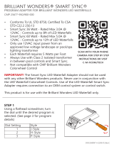
BRILLIANT WONDERS® LED WATERFALL 2
INSTALLATION INSTRUCTIONS & PRODUCT MANUAL
25776-XXX-XXX (BOTTOM PORT LED WATERFALL 2)
25777-XXX-XXX (BACK PORT LED WATERFALL 2)
COVERED BY ONE OR MORE U.S. PATENTS
OR PENDING PATENT APPLICATIONS. SEE
WWW.C-M-P.COM/PATENTS FOR DETAILS.

2
Serious bodily injury or death can result if this waterfall is not
installed and used correctly.
Installers, pool operators and pool owners must read these warning
and all instructions before operating waterfalls.
Turn o power to lights before installation/service. CMP Brilliant
Wonders LED Waterfall 2 is a low voltage light and should never be
electrically connected to a power source other than an approved
pool “Safety Rated,” UL listed, outdoor rated, 12V transformer or
power supply: Brilliant Wonders Color Wheel Control (25650-130-
300) requires a 12V DC power supply; Brilliant Wonders Smart Sync
Adapter (25677-900-000) requires a 12V AC transformer. Failure
to comply will either damage or destroy the light and will void the
warranty.
Before installing this product, read and follow all warning notices and
instructions in this guide. Failure to follow warnings and instructions
can result in severe bodily injury, death or property damage.
This waterfall must be installed by a licensed or certied
electrician or a qualied pool professional in accordance with the
National Electric Code (NEC) or Canadian Electric Code (CEC),
CSA C22.1.
All applicable local installation codes and ordinances must also
be adhered to. Improper installation will create an electrical
hazard which could result in death or serious injury to pool users,
installers, or others due to electric shock. Always disconnect
power to the LED lights before servicing.
Save these instructions. This installation and user guide contains
important information about the installation, operation, and safe
use of this swimming pool/spa light. This guide should be given
to the owner and/or operator of this equipment.
IMPORTANT WARNINGS & SAFETY
INSTRUCTIONS
NOTICE
DANGER
WARNING
WARNING
WARNING
WARNING
CAUTION

3
1. LED Waterfall Unit
2. Front Debris Guard
3. Inlet Debris Guard
4. Rock Trap
5. LED Light Strip (Factory Installed)
6. Power Cable with PVC Conduit Adapter
7. Door Unlatching Tool
8. Door Covers Five Colors (10)
9. Conduit Back Cover
10. Support Trimmer/Clean-out Tool
11. Sliding Cuttable Door (2)
1. Multi-purpose PVC Glue
INCLUDED PARTS
ADDITIONAL TOOLS REQUIRED
PART LIST, TOOL LIST
Figure 1: Parts List
13
10
9
7
2
11 8
4
6
5

4
• Each Brilliant Wonders LED Waterfall 2
is shipped with a debris guard for the
water outlet, and for the water inlet.
• These prevent debris from entering
and damaging the waterfall unit during
installation.
• Debris guards should not be removed
until the waterfall is ready to run.
• Do not leave the waterfall in direct
sunlight. This can cause permanent
damage and warping to the waterfall
unit. (see label)
• This waterfall must be installed as
specied by these instructions.
• It is recommended to keep the unit in
the packaging until the site is prepared
for installation.
• CMP Brilliant Wonders waterfalls are
available in varying sizes. The units
use 1.25 gallons of water per inch of
waterfall per minute. Please size your
water pump accordingly.
• Reference Table 1 when choosing the
correct pumps to use.
Table 1: Required GPM for Proper Operation
Brilliant Wonders Waterfall
Width
Recommended GPM Required
for Proper Performance
12" 15 GPM
18" 22.5 GPM
24" 30 GPM
36" 45 GPM
48” 60 GPM
60” 75 GPM
72” 90 GPM
84” 105 GPM
96” 120 GPM
Use only water that has been properly ltered by an in-line cartridge lter. Failure to properly lter
water may result in a clogged waterfall and a voided warranty.
GENERAL PERFORMANCE GUIDE
PROTECTING DURING INSTALLATION
PRE-INSTALLATION GUIDE
NOTICE
Figure 2: Debris Guards
Leave debris guards
on waterfall face
and inlet throughout
the installation.

5
Figure 5: Overhang Lip 1/8”
WATERFALL: Always leave
minimum 1/8” Overhang
of the lip beyond nished
pool wall
WALL
Figure 3: Concrete Forming Guide (12"-36") Figure 4: Inlet Spacing Guide
• The wall installation is very similar to the concrete/ substrate installation without the
forming process. The dimensional requirements for installation will be the same.
• The lip of the waterfall must be fully supported by the poured substrate (usually gunite
or concrete). It is also recommended that steel rebar be used to further support the
waterfall inside the substrate.
• When forming the area for installation, note that plumbing and electrical notches must
be provided (Figure 3 and 4).
• The waterfall must be installed with a minimum of 1/8” overhang from the nished
surface (Figure 5). Mortar or thinset should be used to secure the waterfall in place.
FORMING THE FOUNDATION INLET SPACING
FOUNDATION GUIDE
Steel rebar support
(Recommended)
Electrical notch
(3.5” W x 3.0” D recommended)
Plumbing notch
(3.5” W x 3.5” D recommended)
E E DD
B C B
A A
12” FALLS A = 8-5/16”
18” FALLS A = 11-5/16”
24” FALLS A = 14-5/16”
36” FALLS A = 20-5/16”
84” FALLS D = 20-13/16“, E = 23-1/2“
96” FALLS D = 22-13/16“, E = 27-1/2“
48” FALLS B = 17-3/8“, C = 18”
60” FALLS B = 19-5/16“, C = 26“
72” FALLS B = 22-5/16“, C = 32“

6
RECOMMENDED PLUMBING FOR THE WATERFALL
1. Use multiple pumps when installing multiple waterfalls.
2. The dedicated pump should be plumbed with a minimum of 2" PVC pipe.
3. VGB compliant suction covers must be used, and they must be installed 18” above the
bottom of the pool.
FOUNDATION & PLUMBING
SETTING THE WATERFALL
For standard pool applications, the waterfall must be installed before the deck and
coping. Place the waterfall in the notches cut in the bond beam or wall application. Utilize
substrate material such as tile, thinset or mortar to make sure that the waterfall is level
with the top of the upper edge of the bond beam.
Fill the gaps around the unit with concrete or similar material in preparation for the tiles
or other material. Cut the tile/material to t under the lip of the waterfall using thinset or
similar substance to secure in place. Ensure the waterfall is level front to back and across
the length of the fall. Complete the electrical installation and plumbing before covering
the top deck.
When installing the nal fascia to the wall whether using tile, stone or other substrate, do
not cover the access doors. These will be required for servicing the unit. (Figure 6)
Do not block access doors with tile, stone or any substrate.
Figure 6: Installation of the waterfall unit.

7
PLUMBING GUIDE
Use only water that has been properly ltered by an in-line cartridge lter. Failure to
properly lter water may result in a clogged waterfall and a voided warranty.
NOTICE
PUMP
3-WAY VALVE
SUCTION LINE
SEPARATE RETURN
TO POOL
BRILLIANT WONDERS
WATERFALL
ROCK TRAP
FILTER/STRAINER
Figure 7: Plumbing Guide
48” - 72" LONGOVER 72" LONG
UP TO 36" LONG
2-WAY VALVE
WATERFALL 84” - 96” LONG
FROM
PUMP/FILTER
PLUMBING LOOP
FROM
PUMP/FILTER
WATERFALL 48” - 72” LONG
FROM
PUMP/FILTER
WATERFALL 12” - 36” WATERFALL 12” - 36”
48" LONG
FROM
PUMP/FILTER
WATERFALL 48” LONG
Figure 8: Recommended Pipe Conguration
Typical Performance at 50’ of Head
1/2 HP 26 GPM
3/4 HP 58 GPM
1 HP 68 GPM
1-1/2 HP 93 GPM
2 HP 106 GPM
3 HP 140 GPM
Maximum Recommended Flow
1-1/2” Pipe for 60 GPM
2” Pipe for 100 GPM
2-1/2” Pipe for 140 GPM
3” Pipe for 225 GPM
BALANCING THE FLOW
It is recommended to use a 3-way valve after the pump to allow the ow to be regulated
between the waterfall and the pool return. The recommended location for this valve is
after the lter near the equipment pad (Figure 7).
When plumbing two or more waterfalls, follow all of the previous instructions with the
addition of a 2-way ball valve for each waterfall. The valve is necessary to balance the
water ow between the units. Proper placement of the valve is shown in (Figure 8). CMP
ball valve part numbers are 25800-151-000 for 1½” and 25800-210-000 for 2”.
4. A lter strainer is required between the pump and the waterfall.
5. Install the supplied Rock Trap (25577-950-000) just before the water line reaches the
waterfall inlet. The Rock Trap does not replace a lter.
48” - 72" LONG
OVER 72" LONG
UP TO 36" LONG
2-WAY VALVE
WATERFALL 84” - 96” LONG
FROM
PUMP/FILTER
PLUMBING LOOP
FROM
PUMP/FILTER
WATERFALL 48” - 72” LONG
FROM
PUMP/FILTER
WATERFALL 12” - 36” WATERFALL 12” - 36”
48" LONG
FROM
PUMP/FILTER
WATERFALL 48” LONG
48” - 72" LONGOVER 72" LONG
UP TO 36" LONG
2-WAY VALVE
WATERFALL 84” - 96” LONG
FROM
PUMP/FILTER
PLUMBING LOOP
FROM
PUMP/FILTER
WATERFALL 48” - 72” LONG
FROM
PUMP/FILTER
WATERFALL 12” - 36” WATERFALL 12” - 36”
48" LONG
FROM
PUMP/FILTER
WATERFALL 48” LONG

8
LED STRIP POWER CABLE CONNECTION
3. Connect power cable connector terminal to
connector terminal of LED strip. Place both into
the cuttable door as shown. Push cuttable door
into side conduit while pulling electric cable
from the back.
2. Remove LED Strip terminal from the door. Pull
power cable and LED strip through the front of
the side conduit and glue adapter into the back.
4. Glue door cover to cuttable door using PVC
glue. OPTIONAL: Opening of cuttable door can
also be lled with grout, plaster, caulk, etc. to
match pool wall. Fill only opening of cuttable
door, do not cover latch hole.
From
Power Cable
Sliding
cuttable door
LED strip quick
disconnect/
connector terminals
Only ll this area.
Do not ll latch
hole.
To
LED strip
Glue adapter
using PVC glue
1. Insert door unlatching tool into the side holes
of the cuttable doors with bent portion facing
up. Once fully inserted, pull tool to remove door.
Wire and terminal from LED strip will slide out
with cuttable door.
Bent portion facing up
To LED strip
Electric
Terminal
LED strip
Power Cable

9
Install power cable through 1” conduit. Use only sweeps, no 90° elbows. Control box must be above
water level. Connect cable to Brilliant Wonders Color Wheel Control, or Brilliant Wonders Smart Sync
Adapter.
For more detailed information please refer to instruction manuals for the Brilliant Wonders Color Wheel Adapter (25650-130-
300), or Brilliant Wonders Smart Sync Adapter (25677-900-000).
BRILLANT
WONDERS COLOR
WHEEL CONTROL
OR
BRILLIANT
WONDERS SMART
SYNC ADAPTER
LED WATERFALL
CONTROL BOX
Control box must be
above water level
1” conduit
90° sweeps only
Control Option 2: Brilliant Wonders Smart Sync
Adapter requires a 12V AC transformer (not
included). Use Smart Sync Adapter option for
Waterfalls installed with other LED products or
automation
12V AC CLASS 2 TRANSFORMER
100-240V AC INPUT12V AC OUTPUT
A/C INPUTA/C OUTPUT
GROUND
BROWN
BLUE
GREEN
BLACK
RED
GREEN
BLACK
WHITE
BLACK
WHITE
To LED strip
Control Option 1: Brilliant Wonders Color Wheel
Control requires a 12V DC power supply (sold
separately).
ON/OFF
PAUSE
KEYS
MODE
KEYS
SPEED
KEYS
BRIGHTNESS
KEYS
12V DC CLASS 2
POWER SUPPLY
100-240V AC INPUT12V DC OUTPUT
A/C INPUTD/C OUTPUT
GROUND
BROWN
BLUE
GREEN
RED
RED
GREEN
BLACK
WHITE
BLACK
To LED strip
CONTROL WIRING
Color Wheel Control and Smart Sync Adapter are incompatible and should not be used together.
NOTICE

10
LED STRIP REMOVAL/REPLACEMENT
GUIDE
3. Reattach wire terminals and place them into
cuttable door as shown. Re-wrap pull-cable
around the spindle and place back into cuttable
door.
2. Remove LED strip by gently pulling the wiring of
the strip. Once removed, detach pull-cable from
old LED strip and tie onto the new one. Start
feeding the LED strip back into the side conduit
while pulling the pull-cable from the other side.¹
4. Reinstall cuttable doors into waterfall. Slowly
push in until latches snap into place. Door latch
will “snap” into place once fully seated in the
side conduit.
From Power Cable
To
LED strip
Detach pull-cable from old
LED strip/ Attach to new
LED strip
IMPORTANT: As you slide back in, LED side of strip
should face towards the center of the waterfall.
1. Use unlatching tool to remove both doors.
(See detailed instructions on previous pages.)
Disconnect wire terminals and unwrap pull-
cable from spindle. Let cables hang freely.
Disconnect terminals
Unwrap pull-cable from spindle
¹TIP: If the LED strip gets caught or stuck during installation or removal, the door unlatching tool may be used to help guide or reposition
around the corners. Insert door unlatching tool into the side conduit using the rounded end to push the LED strip o the corner while pulling
from the opposite side.

11
Situation Solution 1 Solution 2
Can the lip be cut into a
custom shape or radius?
Yes, Brilliant Wonders LED
Waterfall 2 from CMP can come
custom cut from the factory.
Contact CMP for more
information on order placement.
Waterfall has breaks in the
sheeting or does not have a
smooth ow.
Debris may be caught in the lip.
Use the clean out tool or a thin at
tool to clear the lip.
GPM may be inaccurate. Too
little ow or too much ow
through waterfall may prevent
proper water ow. Reference the
chart in this installation guide for
proper GPM.
When using the Colorwheel
Control the LED on my
waterfall is only red or blue.
You may have the incorrect power
supply. A DC transformer/power
supply purchased from CMP is
required to activate the controller.
Wires may be crossed between
the controller and waterfall.
Sequence top to bottom should
be as follows: White, Black,
Green, Red. See detailed wiring
diagram on the controller
instructions or quick reference
card.
Do I always need to use the
screen and rock trap that
came with the waterfall?
We do not recommend using the
screen if possible. Pet hair and
other ne debris can build up over
time and impede the water ow.
The rock trap is always
recommended. Using the rock
trap will capture debris in the
pipes, and prevent it from
building up in the waterfall.
NOTE: During installation, do
not “drag” the pipes along the
ground or in the dirt. This lls
the pipes with dirt and the
waterfall will not work correctly
after installation. (Yes, we have
seen this happen before!)
TROUBLESHOOTING/FAQ
IF YOU HAVE ANY OTHER CONCERNS OR QUESTIONS, CONTACT CS@C-M-P. C O M
IMPORTANT: USE FILTERED WATER ONLY!

12
Situation Solution 1 Solution 2
The LED Strip or cord are
stuck, twisted or dicult to
remove.
The door unlatching tool can be
used to relieve binding inside the
waterfall. Push the tool to the back
of the side conduit and use it to
reposition the LED strip inside the
housing.
I pushed the door unlatching
tool in the side conduit but
the door will not pull out.
Conrm that you can feel a small
catch as the tool opens the latch.
Gently and slightly rotate the
tool side to side to help catch
the sliding door before pulling
out.
One waterfall has more ow
that other waterfalls installed
in the pool.
The supply of water is not
balanced correctly. To get equal
ow from each waterfall unit,
adjust the valves at each waterfall
until the desired ow is achieved.
Review the Plumbing Guide in
these instructions for details
on a proper multiple waterfall
plumbing setup.
The pull-cable broke or
became unattached from the
LED strip. How do I replace it?
If the cable breaks or is pulled
through while untied, a shop
vac can be used to guide it back
through the channel. Push the new
pull-cable into the side channel
making sure to keep it along the
inside wall (the door opening tool
can be used to help guide the
pull-cable into the channel).
Place a shop vac hose over the
opposite side channel opening
and turn on the shop vac. The
shop vac will “suck” the pull-cable
through the waterfall. Reattach to
the LED strip.
If the pull-cable actually tears
through the end of the LED strip,
the cable can be reattached by
tying around the back of the
black overmolded end. The door
unlatching tool can be used to
help guide the LED strip into the
channel if it gets stuck.
TROUBLESHOOTING/FAQ

13
AVAILABLE PARTS & ACCESSORIES
For the most recent instructions, videos and product information visit www.c-m-p.com
BRILLIANT WONDERS® LED WATERFALL 2
REF CMP P/N DESCRIPTION
1 25777-009-100 DOOR COVER, 10 PACK ALL COLORS (FITS LEFT OR RIGHT SIDE)
2 25777-130-017 CUTTABLE SLIDING DOOR FOR 6” LIP WATERFALL
2 25777-130-007 CUTTABLE SLIDING DOOR FOR 12” LIP WATERFALL
3 25777-130-100 12” LED WATERFALL LIGHT STRIP 2
3 25777-180-100 18” LED WATERFALL LIGHT STRIP 2
3 25777-230-100 24” LED WATERFALL LIGHT STRIP 2
3 25777-330-100 36” LED WATERFALL LIGHT STRIP 2
3 25777-430-100 48” LED WATERFALL LIGHT STRIP 2
3 25777-530-100 60” LED WATERFALL LIGHT STRIP 2
3 25777-630-100 72” LED WATERFALL LIGHT STRIP 2
3 25777-730-100 84” LED WATERFALL LIGHT STRIP 2
3 25777-830-100 96” LED WATERFALL LIGHT STRIP 2
4 25777-130-030 DOOR UNLATCHING TOOL
5 25777-130-065 TRIMMING/ CLEANING TOOL
6 25777-130-200 100' LED POWER CABLE
7 25777-130-071 CONDUIT BACK PLUG
8 25777-130-074 BACK DEBRIS GUARD
1
2
3
6
7
8
5
4

14
NOTES

15
CMP Customer Service & Tech Support
Toll Free: 1-800-733-9060
FAX: 770-632-7115
suppor[email protected]
Warranty Questions
Support Resource & Videos Online
c-m-p.com/resourcecenter

CUSTOM MOLDED PRODUCTS | 36 HERRING ROAD, NEWNAN, GA 30265 | WWW.C-M-P.COMab012020
CMP DOCUMENT 90500-257-771_REV E
/