Page is loading ...

MANUAL
INSTRUCTION

STEP 01
Locate the hinges and insert eight mid-way into the wing's trailing edge (four in each
wing half half). Each of the slots has been pre-cut for the hinges but may need gentle
opening up with a sharp knife. Using thin cyano, pour a couple of drops onto each
hinge - above and below - ensuring the glue soaks into the hinge and the surrounding
wood.
Page 1
STEP 02
Carefully slide each aileron into position, ensuring a gap-free hinge line. Make sure that
each aileron lines up with the wing tips and that they are free to move through their
entire travel. Minimise any hinge gap, then carefully add a couple of drops of thin cyano
to the top and bottom of each hinge ensuring that the glue does not run through the
hinge line onto the bottom of the wing. Turn the wing over and drop more cyano onto
each hinge from the other side.
STEP 03
Locate the aileron servo apertures in the underside of the wing and
check that your choice of servo fits. Adjust the size of the mounting
holes with a sharp knife if required. Carefully pass each aileron lead
through to the centre of the wing using the length of cotton already
in the wing. You may need to extend the length of your aileron servo
leads using a pair of extension leads. Screw the servos in position using
the mounting screws supplied with your radio.
STEP 04
Locate the aileron control horns. They are simply glued in position
on the aileron at the reinforced section immediately to the rear of
the aileron servo cutout. Align the horn hingeline and centre over the
reinforced area as shown. Mark and pilot drill two mounting holes then
glue the horn in place using cyano. Repeat for the other aileron.
STEP 06
Locate the tailplane. Mark a centreline on the rear of the tail as shown. Temporarily
fit the wing to the fuselage, slide the tail in place and make sure it is square to the
fuselage. Measuring from the rear of the wing to the tailplane on each side, adjust the
tailplane's position until both measurements are the same.
STEP 05
Locate a plain wire aileron control rod. Slide a nylon keeper on
the wire, then form a 90° bend 5mm from the end. Attach a servo
connector to your aileron servo's output arm and slide the pushrod
through it. Now connect the bent end to the control horn and close
the keeper. Centre the servo and aileron, then tighten the servo
connector's screw. Repeat for the other aileron and check for free
aileron movement through the entire range of throw.
THE WING
Mini Bossanova - Instr uctions
THE TAIL

STEP 07
Carefully mark the tailplane on the top and bottom where it enters the fuselage using
a soft, water-soluble felt tip pen. Now remove the tailplane.
Page 2
STEP 08
Cut away the covering from just inside the marked lines to give a
film-free surface for the glue to bond on the top and the bottom of
the tailplane.
IMPORTANT NOTE: Ensure that only the film is cut - not
the tailplane - as this will seriously weaken the structure.
STEP 09
Locate the four elevator hinges (two each side) and insert them half way into the pre-
cut slots. Using thin cyano, pour a couple of drops onto each hinge - above and below
- ensuring the glue soaks into the hinge and the surrounding wood.
STEP 10
Locate the bent wire elevator joiner and place it in the rear of the
tailplane slot in the fuselage. VERY IMPORTANT: Do not omit
this step as it will be almost impossible to fit it after the
tailplane has been glued in position. Now glue the tailplane
in position using epoxy, checking that it is correctly aligned and square
to the fuselage and wing seat. You may wish to use masking tape to
protect the covering whilst you do this (removing it as soon as you are
satisfied with the alignment and before the epoxy cures). Any excess
epoxy can be wiped from the model before it cures using methylated
spirit or methanol.
STEP 12
Once the epoxy has cured, flex the elevators to ensure that they move
freely through their entire range of travel.
STEP 11
Once the glue has thoroughly cured, the elevators can be fitted. Apply
a small quantity of 5 minute epoxy to the elevator joiner as shown.
Now slide the elevator onto the wire joiner and ensure that both
hinges enter the pre-cut slots in the elevator. Ensuring a gap-free hinge
line, add a couple of drops of thin cyano to the top and bottom of each
hinge ensuring that the glue does not run through the hinge line onto
the bottom of the tail. Turn the model over and drop more cyano onto
each hinge from the other side. Repeat for the second elevator half.
Mini Bossanova - Instr uctions

STEP 13
Locate the three rudder hinges and slide them half way into the rudder. Using thin
cyano, pour a couple of drops onto each hinge - above and below - ensuring the glue
soaks into the hinge and the surrounding wood.
Page 3
STEP 14
Screw the pre-bent tailwheel assembly to the rear of the fuselage as
shown after pilot drilling holes for the mounting holes. Ensure that
the wire is aligned with the rear of the fuselage. Carefully drill a hole
in the bottom of the rudder to accept the bent end of the tailwheel
wire and test fit the rudder.
STEP 15
Apply a small quantity of epoxy onto the wire. Slide the rudder into
position, ensuring free movement left and right and a gap-free hinge
line. Now apply a couple of drops of thin cyano to each side of each
hinge taking care not to allow the adhesive to run through the gap
onto the other side of the model.
STEP 16
Locate the three part aluminium motor mount. Attach your choice of
brushless motor to the forward part of the mount as shown. Screw
the remaining two parts of the motor mount to the front bulkhead
as shown using the screws and captive nuts supplied.
STEP 18
Fit your choice of propeller adaptor on the motor and test fit the ply
spinner rings over the adaptor. Thread the motor wires through the
mount and front bulkhead as shown.
STEP 17
Now screw the motor in position as shown using the screws and
nyloc nuts supplied with the mount. Note that the motor mount is
offset from the centre line as shown to give the correct amount of
right thrust.
Mini Bossanova - Instr uctions
MOTOR

STEP 19
Slide the cowl in position. Re-fit the plywood spinner rings and
mount your propeller. Holding the cowl in place and ensuring a small,
even gap between the front of the cowl and spinner rings, mark the
positions of the cowl mounting screws. Pilot drill the holes then
attach the cowl using the four self tapping screws supplied.
Page 4
STEP 20
Locate the pre-painted spinner nosecone. Carefully trim away enough plastic to
allow it to fit onto the plywood spinner rings without touching the propeller. Now
glue the spinner nosecone onto the plywood rings ensuring it is square by turning
the propeller slowly. Use minimal glue for this joint is allow the spinner nose cone
to be removed when changing props.
STEP 21
Locate the pre-bent undercarriage and mounting screw, washers and retaining nut.
Ensure that the wheels spin freely on the axles.
STEP 22
Slide the undercarriage through the pre-cut slot in the underside of the fuselage as
shown. Place a washer on the mounting screw and push it through the pre-drilled
hole from the wing opening and through the loop in the top of the undercarriage. Fit
another washer, followed by the nut, and tighten.
STEP 24
Trim the covering away from the pre-drilled wing mounting bolt
access hole. You may wish to seal the edges of the film with a covering
iron. With the wing bolted in position, test the fit of the fairing.
Holding the fairing in place, mark its position on the wing then trim
the covering from the wing centre section inside the marked lines.
VERY IMPORTANT: Ensure that only the film is cut - not
the wing - as this will seriously weaken the structure.
STEP 23
Complete the installation of the undercarriage by screwing the lower hatch in place
with the self tapping screw supplied.
Mini Bossanova - Instr uctions
UNDERCARRIAGE
UNDERWING FAIRING

STEP 25
Mix up sufficient 5 minute epoxy and glue the wing fairing in position
using tape to hold it in position as the glue cures. Ensure that the
fairing aligns correctly to the fuselage and that the glue does not
come into contact with the fuselage. Any excess epoxy can be wiped
from the model before it cures using methylated spirit or methanol.
Page 5
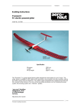
STEP 26
Mount your rudder and elevator servos in place between the two servo bearers at
the rear of the fuselage's canopy opening. Note that both should be fitted with their
outputs towards the front of the model. Pilot drill the bearers and install the servos
using the screws supplied with your radio.
STEP 27
Trim the servos' output arms as shown, then locate the elevator and rudder pushrod
wire. Slide a nylon keeper on each wire, then form a 90° bend 5mm from the end.
Connect the pushrods to the servo output arms and slide the wires into their pre-
fitted tubes.
STEP 28
Fit a pushrod connector to the rudder and elevator control horns.
Aligning each with their hinge lines, pilot drill and cyano them in place
- looking from the rear, the rudder horn is fitted on the left hand side
of the rudder and the elevator horn is fitted on the underside of
the right hand elevator. With the servos centred and the rudder and
elevator level, tighten the pushrod connectors' screws.
STEP 30
Temporarily slide your Li-Po battery in position in front of the receiver. Dense foam
receiver packing can be used to retain it place once the balance point has been
checked. To complete the model, fit the canopy by inserting its locating dowel in the
pre-drilled bulkhead then lowering into place until the pre-fitted magnet snaps it
closed. Simply lift up the rear of the canopy and slide backwards to remove.
STEP 29
To complete the radio installation, mount your receiver to the rear of the balsa radio
tray then connect and mount your ESC to the fuselage side next to the receiver. Use
double sided foam tape or velcro for each. If using a switch, mount it in the radio
bay too. Drill a small hole in the rear fuselage deck behind the canopy for your aerial
to exit. Fix the free end of the aerial to the fin using tape, a band or pass through a
drilled hole.
COMPLETING THE RADIO INSTALLATION
Mini Bossanova - Instr uctions
• RUDDER SERVO
ELEVATOR SERVO •

Page 6
Mini Bossanova - Instr uctions
CONTROL THROWS
For initial flights, we recommend the following control throws
- all measured from the widest point of the control surface:-
Elevator: 30mm up
30mm down
Rudder: 50mm left
50mm right
Ailerons: 40mm up
40mm down
Mixing: Elevator to flap mix can be used with the ailerons moving
50% of their total movement when full elevator is applied.
Exponential: We recommend 50% exponential on the ailerons
and 20% exponential on the elevator. For Futaba radios, these
are negative figures - please check with the instructions supplied
with your radio for guidance.
Once comfortable with the Mini Bossanova the control throws
can be increased for 3D flying.
POWER SYSTEM
The Mini Bossanova can accept a variety of power systems, but
the following has proven to be a very successful combination:
M-XTRA2826/15 XTRA 2826/15 Brushless Motor
P-XTRA-16BL XTRA 16Amp Brushless Speed
Controller
O-IM3S1P130020C Impulse Power 11.1v (3 cell) 1300mAh
Li-Po Battery Pack
E-LP10047 APC 10 x 4.7" Slow Fly Propeller
BALANCING THE MODEL
The Centre of Gravity position should be 85mm back from the
leading edge measured at the root of the wing. Support the
completed model at this point and move the Li-Po battery as
necessary to achieve a slightly nose down attitude. A model that
is not correctly balanced will not perform as it should and, at
worst, be unstable or unflyable, leading to damage to the model
or injury to yourself or others. Do not miss out this step in
completing your Mini Bossanova! Once happy with the balance
point, mark the position of the Li-Po battery and use dense foam
packing to ensure that it cannot move backwards or forwards
in flight.
PRE-FLIGHT CHECKS
• Completely charge your transmitter and Li-Po flight battery
before flying.
• Carefully check your model over to ensure that all screws are
tight and everything is well bonded.
• Double-check the Mini Bossanova’s Centre of Gravity
position.
• Check the control surfaces for both the correct throw and
direction. Ensure that each surface moves freely, without any
binding.
• Check the receiver aerial is fully extended.
• Ensure the wing bolt is tight.
• Ensure the Li-Po battery is securely mounted and cannot move
in flight.
Before every flying session you MUST check the control range
of your R/C system.
Have a helper hold the model ensuring that they are clear of the
propeller. With the transmitter and model switched on, retract
the transmitter aerial and walk away moving the elevator stick
on the transmitter.
Run the motor to full power and repeat the elevator movements.
You should be able to walk between 25-30 metres without
interference or losing control. If you lose control or the radio
appears to have interference do not attempt to fly.
IMPORTANT
The Mini Bossanova is a highly aerobatic model capable of
extreme 3D manoeuvres. When fitted with a powerful brushless
motor, it offers almost unlimited performance. However, it is not
designed to be flown fast and should be fitted with the correct
choice of 3D ‘paddle’ prop having broad blades and very low
pitch. Ensure that your choice of micro servo can handle the
large control surfaces.
Always fly responsibly and safely.
Distributed to your local model shop by:
Ltd., 241 Green Street, Enfield, EN3 7SJ. United Kingdom..
Made in China

/