Page is loading ...

User and maintenance instructions
Date of issue July 2018
Form number 671087
Version 2
Model series 586
Cordless grease gun
Battery charger
included

Description
Model 586 grease guns are designed to
dispense petroleum-based greases (NLGI 1/
NLGI 2) for general lubrication applications.
A 36-inch (0.91 meter) long high-pressure
whip hose, heavy-duty grease coupler,
charger and molded carrying case are
included. Tool is equipped with a battery
charge level indicator.
The guns use an electric motor with three
stages of gear reduction. A crank and yoke
mechanism drives a reciprocating piston
pump. The motor is powered by a recharge-
able 14 Volt/2 000 mAh lithium-ion battery
pack.
Each model gun is designed for 3-way
loading; cartridge, suction, and loader pump
(requires optional loader fitting 322610).
The guns are spring-primed and include an
air bleed valve to aid priming.
Battery charger
included
Sound pressure (LPA) 73 dB(A), uncertainty (K) 3 dB(A)
Acoustic power (LWA) 84 dB(A), uncertainty (K) 3 dB(A)
Vibration emission value (ah0.5m/s^2)
0.7 m/s2, uncertainty (K) 1.5 m/s2
Optional accessories
Shoulder
strap
Mobile batter charger
(12 - 24 V DC input)
Loader
fitting
339812 343289 322610
Model Battery qunatity Battery charger
586-A 1 120 V AC/60 Hz
586-B 2 120 V AC/60 Hz
Specifications
Delivery capacity Grease cylinder capacity Hose assembly
Maximum pressure Flow rate fully charges Bulk Cartridge size Pressure rating Length Weight (empty)
10 000 psi (690 bar) 5.6 oz./min.
(160 grams/min.)
15 cartridges 16 oz.
(454 grams)
14 oz.
(397 grams)
10 000 psi
(690 bar)
36 in
(0.9 m)
6.3 lbs (2,9 kg)
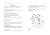
Fig. 1
Cordless grease gun series 586 heading
2

1
2
3
4
5
6
7
8
9
10
11
12
13
14
15
16
17
18
19
20
21
22
23
24
25
26
27
28
29
30
31
32
33
34
35
36
37
38
39
40
11
10
7
8
4
2
3
41
42
43
2)
1)
Fig. 2
Exploded view of 586
1)
Only suitable substitute 6304-B Coupler, grease. Item 25 must be removed when using this coupler. 340388 Relief valve with gasket.
2)
Support yoke during roll pin removal.
3

Illustrated parts breakdown list
Item Description Part number Quantity Item Description Part number Quantity
1 Screw, tapping
3)
4 25 Insert, coupler
6)
1
2 Washer, lock
3)
8 26 Yoke
7)
1
3 Screw, machine
3)
8 27 Pin, roll
5)
1
4 Housing
3)
1 28 Piston 1
5 Hose, grease 340067 1 29 Battery, indicator
4)
1
6 Coupler, grease 308730
6)
1 30 Battery connector
4)
1
7 Screw, M3x6
4)
6 31 PCB
4)
1
8 Washer, m3 lock
4)
6 32 Trigger 1
9 Cover, head 1 33 Cylinder, grease 339820
1
10 Ring, retaining
5)
2 34 Switch
4)
1
11 Washer, 0.24 x 0.67 in
5)
2 35 Gasket (copper)
1)5)
1
12 Bearing, roller
5)
1 36 Plug, check
1)
1
13 Gear, output 1 37 Spring, check
1)
1
14 Head and bearing assembly
5)
1 38 Ball, check,
3
/8 in
1)
1
15 Gear, output pinion 1 39 Gasket
1)
336523
1
16 Gear, planet (2nd stage) 3 40 Plug
17 Gear, internal 1 41 Battery, 14.4V, li models 58A, C
battery, 14.4V, li models 586B, D
343432
343500
1
2
18 Gear, sun (2nd stage) 1 42 Charger, battery (120 V AC/60hz) 1
19 Gear, planet (1st stage) 1 43 Charger, battery (230 V 50hz) 343501 1
20 Washer
4)
2 44 Case, carrying Not shown 1
21 Motor mount
4)
1 45 Bleed valve
2)
Not shown 1
22 Screw, M3x16
4)
4 46 Spring, trigger Not shown 1
23 Motor (w/sun gear)
4)
393795-27 1 47 Spring, bleed valve
2)
Not shown 1
24 Holster 1 48 O-ring
2)
Not shown 1
1)
Repair kit 393795-6, check valve kit.
2)
Repair kit 393757, bleed valve kit
3)
Repair kit 393815-01, housing kit
4)
Repair kit 393815-02, electrical kit. Must be replaced by authorized service center only. Warranty void if service center not used.
5)
Repair kit 393795-12, head kit. Must be replaced by authorized service center only. Warranty void if service center not used.
6)
Optional part. Only suitable substitue 6304-B coupler, grease. Item 25 must be removed when using this coupler. 340388 relief valve with gasket.
7)
Support yoke during roll pin removal.
4

Intended use
These model guns are designed to dispense
petroleum-based greases for general
lubrication applications.
Safety instructions
General power tool safety
warnings
Save all warnings and instructions for future
reference. The term “power tool” in all of the
warnings listed below refers to your mains
operated (corded) power tool or battery
operated (cordless) power tool.
1 Work area safety
1.1 Keep work area clean and well lit.
Cluttered or dark areas invite
accidents.
1.2 Do not operate power tools in explo-
sive atmospheres, such as in the
presence of flammable liquids, gases
or dust. Power tools create sparks
which may ignite the dust or fumes.
1.3 Keep children and bystanders away
while operating a power tool.
Distractions can cause you to lose
control.
2 Electrical safety
2.1 Power tool plugs must match the
outlet. Never modify the plug in any
way. Do not use any adapter plugs
with earthed (grounded) power tools.
Unmodified plugs and matching
outlets will reduce risk of electric shock.
2.2 Avoid body contact with earthed or
grounded surfaces such as pipes,
radiators, ranges and refrigerators.
There is an increased risk of electric
shock if your body is earthed or
grounded.
WARNING
Read all safety warnings and
all instructions. Failure to
follow the warnings and
instructions listed below may
result in electric shock, fire
and/or serious injury.
2.3 Do not expose power tools to rain or
wet conditions. Water entering a
power tool will increase the risk of
electric shock.
2.4
Do not abuse the cord. Never use the cord
for carrying, pulling or
unplugging the power tool. Keep cord
away from heat, oil, sharp edges or
moving parts. Damaged or entangled
cords increase the risk of electric
shock.
2.5 When operating a power tool
outdoors, use an extension cord
suitable for outdoor use. Use of a cord
suitable for outdoor use reduces the
risk of electric shock.
2.6 If operating a power tool in a damp
location is unavoidable, use a residual
current device (RCD) protected supply.
Use of an RCD reduces the risk of
electric shock.
3 Personal safety
3.1 Stay alert, watch what you are doing
and use common sense when
operating a power tool. Do not use a
power tool while you are tired or
under the influence of drugs, alcohol
or medication. A moment of inatten-
tion while operating power tools may
result in serious personal injury.
3.2 Use personal protective equipment.
Always wear eye protection.
Protective equipment such as dust
mask, non-skid safety shoes, hard
hat, or hearing protection used for
appropriate conditions will reduce
personal injuries.
3.3 Prevent unintentional starting.
Ensure the switch is in the off-
position before connecting to power
source and/or battery pack, picking up
or carrying the tool. Carrying power
tools with your finger on the switch or
energising power tools that have the
switch on invites accidents.
3.4 Remove any adjusting key or wrench
before turning the power tool on.
A wrench or a key left attached to a
rotating part of the power tool may
result in personal injury.
3.5 Do not overreach. Keep proper footing
and balance at all times. This enables
better control of the power tool in
unexpected situations.
3.6 Dress properly. Do not wear loose
clothing or jewellery. Keep your hair,
clothing and gloves away from moving
parts. Loose clothes, jewellery or long
hair can be caught in moving parts.
3.7 If devices are provided for the
connection of dust extraction and
collection facilities, ensure these are
connected and properly used.
Use of dust collection can reduce dust-
related hazards.
4 Power tool use and care
4.1 Do not force the power tool. Use the
correct power tool for your applica-
tion. The correct power tool will do the
job better and safer at the rate for
which it was designed.
4.2 Do not use the power tool if the switch
does not turn it on and off. Any power
tool that cannot be controlled with the
switch is dangerous and must be
repaired.
4.3 Disconnect the plug from the power
source and/or the battery pack from
the power tool before making any
adjustments, changing accessories, or
storing power tools. Such preventive
safety measures reduce the risk of
starting the power tool accidentally.
4.4 Store idle power tools out of the reach
of children and do not allow persons
unfamiliar with the power tool or
these instructions to operate the
power tool. Power tools are danger-
ous in the hands of untrained users.
4.5 Maintain power tools. Check for mis-
alignment or binding of moving parts,
breakage of parts and any other con-
dition that may affect the power tools
operation. If damaged, have the
power tool repaired before use. Many
accidents are caused by poorly main-
tained power tools.
4.6 Keep cutting tools sharp and clean.
Properly maintained cutting tools with
sharp cutting edges are less likely to
bind and are easier to control.
4.7 Use the power tool, accessories and
tool bits etc. in accordance with these
instructions, taking into account the
working conditions and the work to be
performed. Use of the power tool for
operations different from those
intended could result in a hazardous
situation.
5

WARNING
The vibration emission value during
actual use of the power tool can differ
from the declared value depending on
the ways in which the tool is used.
The vibration level may increase above
the level stated.
WARNING
To reduce the risk of injury,
the user must read the
instruction manual.
5 Battery tool use and care
5.1 Recharge only with the charger
specified by the manufacturer.
A charger that is suitable for one type
of battery pack may create a risk of
fire when used with another battery
pack.
5.2 Use power tools only with specifically
designated battery packs. Use of any
other battery packs may create a risk
of injury and fire.
5.3
When battery pack is not in use, keep it
away from other metal objects, like
paper clips, coins, keys, nails, screws,
or other small metal objects, that can
make a connection from one terminal
to another. Shorting the battery
terminals together may cause burns
or a fire.
5.4 Under abusive conditions, liquid may
be ejected from the battery; avoid
contact. If contact accidentally occurs,
flush with water. If liquid contacts
eyes, additionally seek medical help.
Liquid ejected from the battery may
cause irritation or burns.
6 Service
6.1 Have your power tool serviced by a
qualified repair person using only
identical replacement parts. This will
ensure that the safety of the power
tool is maintained.
Safety of others
• This appliance is not intended for use by
persons (including children) with reduced
physical, sensory or mental capabilities, or
lack of experience and knowledge, unless
they have been given supervision or
instruction concerning use of the appli-
ance by a person responsible for their
safety.
• Children should be supervised to ensure
that they do not play with the appliance.
Residual risks
Additional residual risks may arise when
using the tool which may not be included in
the enclosed safety warnings. These risks
can arise from misuse, prolonged use etc.
Even with the application of the relevant
safety regulations and the implementation
of safety devices, certain residual risks can
not be avoided. These include:
• Injuries caused by touching any rotating/
moving parts.
• Injuries caused when changing any parts,
blades or accessories.
• Injuries caused by prolonged use of a tool.
When using any tool for prolonged periods
ensure you take regular breaks.
• Impairment of hearing.
• Health hazards caused by breathing dust
developed when using your tool
(example:- working with wood, especially
oak, beech and MDF.)
Vibration
The declared vibration emission values
stated in the technical data and the declaration
of conformity have been measured in
accordance with a standard test method
provided by EN 60745 and may be used for
comparing one tool with another.
The declared vibration emission value may
also be used in a preliminary assessment of
exposure.
When assessing vibration exposure to
determine safety measures required by
2002/44/EC to protect persons regularly
using power tools in employment,
an estimation of vibration exposure should
consider, the actual conditions of use and the
way the tool is used, including taking account
of all parts of the operating cycle such as the
times when the tool is switched off and when
it is running idle in addition to the trigger
time.
Labels on tool
The following symbols are shown on the
tool:
6

Your charger is double insulated;
therefore no earth wire is
required. Always check that the
mains voltage corresponds to the
voltage on the rating plate.
Never attempt to replace the charger unit
with a regular mains plug.
• If the supply cord is damaged, it must be
replaced by the manufacturer or an
authorised Alemite service centre in order
to avoid a hazard.
Batteries
Run the battery down completely,
then remove it from the tool
• NiCd, NiMH and Li-Ion batteries are
recyclable. Take them to any authorised
repair agent or a local recycling
Additional safety instructions for batteries
and chargers
Batteries
• Never attempt to open for any reason.
• Do not expose the battery to water.
• Do not store in locations where the
temperature may exceed 104 °F.
• Charge only at ambient temperatures
between 50 and 104 °F.
• Charge only using the charger provided
with the tool.
• When disposing of batteries, follow the
instructions given in the section
Protecting the environment.
Do not attempt to charge
damaged batteries
Chargers
• Use your Alemite charger only to charge
the battery in the tool with which it was
supplied. Other batteries could burst,
causing personal injury and damage.
• Never attempt to charge non-rechargeable
or defective batteries.
• Have defective cords replaced
immediately.
• Do not expose the charger to water.
• Do not open the charger.
• Do not probe the charger.
Electrical safety
Time-lag miniature
fuze link, 2A
IEC
IEEE/ANSI
IEEE/ANSI
Read the instruction manual
before use
Maintenance
Your Alemite tool has been designed to
operate over a long period of time with a
minimum of maintenance.
Continuous satisfactory operation depends
upon proper tool care and regular cleaning.
Your charger does not require any main-
tenance apart from regular cleaning.
Regularly clean the ventilation slots in
your tool and charger using a soft brush or
dry cloth.
WARNING
Before performing any maintenance on
the tool, remove the battery from the
tool. Unplug the charger before cleaning
it.
• Regularly clean the motor housing using a
damp cloth.
Do not use any abrasive or solvent-based
cleaner.
• Regularly open the chuck and tap it to
remove any dust from the interior.
Protecting the environment
Separate collection. This product
must not be disposed of with
normal household waste
Should you find one day that your Alemite
product needs replacement, or if it is of no
further use to you, do not dispose of it with
household waste. Make this product availa-
ble for separate collection.
Separate collection of used
products and packaging allows
materials to be recycled and used
again. Re-use of recycled
materials helps prevent environmental pol-
lution and reduces the demand for raw
materials
.
Local regulations may provide for separate
collection of electrical products from the
household, at municipal waste sites or by the
retailer when you purchase a new product.
The charger is intended for
indoor use onl
7

Specific safety rules
WARNING
The gun can develop high pressure up
to 10 000 psi (690 bar). Rupture of
components can inject grease into skin
and eyes, causing serious injury and
possible amputation. If injured, seek
immediate medical attention.
Do not operate without proper safety
protection, gloves, and goggles.
Hold hose at spring guard only. Do not
use if hose is damaged or worn. Inspect
hose before each use. Use only Alemite
340067 grease whip hose. Use only
Alemite grease coupler 308730.
This gun uses lubricants, that may be
flammable and poisonous if ingested.
Do not use gun near open flame or
other fire hazards. Read all warnings on
lubricants before using this gun.
Use ear protection to reduce the risk
of induced hearing loss.
Disconnect battery from gun before
changing accessories, storing gun or
unscrewing grease cylinder from the
gun.
WARNING
The gun can be equipped with an
optional low-pressure loader fitting
322610. Do not substitute with a
high-pressure grease fitting.
Personal injury can occur due to
excessive pressure.
The use of a grease fitting will void the
warranty.
Loading the Gun
NOTE
Refer to fig. 2 for component
identification on the following
procedures.
Cartridge loading
1
Unscrew grease cylinder (33) from the gun.
2
Pull the follower rod and engage the groove
in the follower rod with the slot in the
grease cylinder cap.
3 Remove the plastic cap from the cartridge.
4
Apply a film of grease to the exposed inside
surface of the cartridge.
5
Insert the cartridge into the grease cylinder.
NOTE
This is only necessary for a new gun.
6 Remove the tabbed seal from the
cartridge.
7 Screw the grease cylinder onto the gun.
8 Disengage the follower rod from the slot in
the grease cylinder cap.
9 Push the follower rod into the grease
cylinder.
Suction loading
1 Unscrew grease cylinder (33) from gun.
2
Insert the head of the grease cylinder below
the surface of the grease.
3 Slowly pull the follower rod outward from
the grease cylinder cap until the groove is
visible.
4 Engage the groove in the follower rod with
the slot in the grease cylinder’s cap.
5 Screw the grease cylinder onto the gun.
6 Disengage the follower rod from the slot in
the grease cylinder cap.
7 Push the follower rod into the grease
cylinder.
Loader pump
1 Pull the follower rod and engage the
follower by rotating the rod.
2 Seat the loader fitting into the loader
coupler.
3 Push down to hold the coupler valve open.
4
Operate the pump and view the movement
of the follower rod.
5 Discontinue pump operation once the
groove on the follower rod is visible.
6 Disengage follower rod from follower and
push into the grease cylinder.
CAUTION
The loader fitting on the gun must mate
with the loader coupler. The pump may
not operate if the components are not
compatible.
8

Priming the gun
In most cases the gun will prime simply by
operating the trigger several times.
Should grease fail to appear, air must be
bled.
Force prime
This process manually assists air within the
gun to be bled at the bleed valve.
1 Pull the follower rod and engage the
follower by rotating the rod.
2 Depress bleed valve (45) and at the same
time push on the follower rod.
Once the air is eliminated, operate the gun
several times.
Once grease appears, disengage the
follower rod from the follower and push into
the grease cylinder.
Check valve contamination
Should the gun fail to prime; the outlet
check may be held open. Remove plug (36),
clean ball (38), and the ball seat of head (14).
Gun operation
Battery (41) is intentionally shipped with a
low charge. Charge the battery prior to use.
Refer to the battery charger operation
section for details.
CAUTION
The gun is equipped with software to
protect the motor. When a blocked
bearing, line, or grease fitting causes the
gun to stall, the software will cut power
to the motor. If this situation occurs,
release the trigger immediately.
For maximum motor life, avoid
operating at stall.
WARNING
Before using the battery charger read all
instructions and cautionary markings
on battery charger (42, 43),
battery (41), and products using the
battery.
An extension cord should not be used
unless absolutely necessary. Use of an
improper extension cord could result in
a risk of fire and electric shock. If an
extension cord must be used, make sure
it is 18- gauge. Check to ensure that the
pins on the plug of the extension cord
are the same number, size, and shape
as those of the plug on the charger.
Make sure that the extension cord is
properly wired and in good electrical
condition.
Do not incinerate the battery, even if it
is severely damaged or completely worn
out. The battery may explode in fire.
Risk of electric shock 120 V AC or
230 V AC present at charfer terminals.
Do not expose battery to spark or
flame. Battery liquid may burn.
Do not splash or immerse in water or
other liquids. This may cause premature
cell failure.
Never attempt to open the battery
pack for any reason. If the plastic bag of
the battery pack breaks or cracks, return
to a service center for recycling.
Failure to comply may result in death
or serious injury.
CAUTION
Do not expose the charger to rain, snow,
or frost.
Make sure the cord is located so that it
will not be stepped on, tripped over, or
otherwise subjected to damage or
stress.
Do not operate the charger with
damaged cord or plug.
Replace immediately.
Do not operate the charger if it has
received a sharp blow, been dropped, or
otherwise damaged in any way.
Do not disassemble the charger.
The charger is designed to operate on
standard household electrical power.
Do not attempt to use it on any other
voltage.
Consecutive charging may cause
overheating. If you need to recharge the
battery consecutively, wait for
15 minutes to allow the charger to cool.
Do not insert foreign material into the
slot for the battery in the charger stand.
Do not disassemble the battery.
Do not store the gun and battery
assembly in locations where the
temperature may reach or exceed
104° F (40° C).
Do not short-circuit the battery.
Do not place the charger in an area of
extreme heat or cold. It works best at
normal room temperature.
Battery and Charger Safety
Rules
This manual contains important safety and
operating instructions for battery part
number 343432 and battery chargers
343500 and 343501.
9

Battery charger
operation
Charge the battery only with the charger
provided or optional mobile charger 343289.
Make sure power circuit voltage is same as
that shown on the charger specifications
plate. Ensure the battery properly engages
with the charger’s contacts.
Function of red and green
lights
When the charger is powered on, the Green
light will flash one time.
Green light flashing
Charging.
Green light on
Battery is fully charged.
Red light flashing at 4HZ
Bad battery condition. The charger has the
ability to detect a weak or damaged battery.
If this LED function occurs, do not continue
to charge the battery. Return it to a service
center or a collection site for recycling.
Red light flashing at 1hz/5hz
Hot/cold battery. When the charger detects
that a battery is excessively hot or cold,
charging is suspended until the battery has
normalized. Once battery is at a temperature
between to 40° F (4° C) and 104° F (40° C),
the charger automatically switches to charg-
ing mode. Battery overheating could be
attributed to:
1 Long continuous running
2 Hot ambient temperature
3 One or more cells are damaged
The battery will become slightly warm to the
touch while charging. This is normal and
does not indicate a problem.
Leaving the battery in the
charger
The battery can be left connected in the
charger with the green led glowing indefi-
nitely. The charger will keep the battery fresh
and fully charged. The charger features an
automatic tune-up mode which equals or
balances the individual cells within the
battery to enable it to function at peak
capacity. Batteries should be tuned-up
weekly or whenever the battery no longer
delivers the same amount of work.
To use the automatic tune-up mode, place
the battery in the charger for a minimum of
8 hours.
10

EC declaration of
conformity
Alemite, LLC
167 Roweland Drive,
Johnson City, Tennessee, USA, 37601
Declares that under the sole responsibility
for supply of the machinery described as:
TYPE/SERIES: Cordless Grease Gun,
MODEL: 586-A, 586-B, 586-C, 586-D
These products are in compliance with the
following European Community Directives:
2011/65/EC, 2006/42/EC, 2014/30/EU
The following standards were used to
verify compliance with the directives:
EN55014-1, EN55014-2, EN50581,
EN60745
Approved by: Date 05/16/2016
Robert Hoefler
Director of Engineering/Product
Development
EC declaration of
conformity
Alemite, LLC
167 Roweland Drive,
Johnson City, Tennessee, USA, 37601
Declares that under the sole responsibility
for supply of the machinery described as:
TYPE/SERIES: Battery charger, MODEL:
343501
This product in compliance with the fol-
lowing European Community directives:
Low Voltage Directive 2014/32/EU; Machin-
ery Directive 2006/42/EC
Electromagnetic Comparability Directive
2014/30/EU. The following standard were
used to verify compliance with the directives:
IEC 60335-1:2010, IEC60335-2-
29:2002+A1:2004+A2:2009,
EN 60335-1:2012, EN 60335-2-
29:2004+A2:2010, AS/NZS 60335-
1:2011+A12:2012, AS/NZS
60335.2.29:2004+A1:2004+A2:2010
EN 62233:2008, EN
55014-1:2006+A1:2009+A2:2011,
EN 55014-2:1997+A1:2001+A2:2008,
EN 61000-3-2:2006+A1:2009+A2:2009,
EN 61000-3-3:2008
Approved by: Date 05/16/2016
Robert Hoefler - Director of Engineering/
Product Development
U
L
11

alemite.com
® Alemite, LLC is a registered trademark.
The contents of this publication are the copyright of the publisher and may not be reproduced (even
extracts) unless prior written permission is granted. Every care has been taken to ensure the accuracy
of the information contained in this publication but no liability can be accepted for any loss or damage
whether direct, indirect or consequential arising out of the use of the information contained herein.
July 2018 · Form 671087 Version 2
/