Page is loading ...

Alemite, LLC
167 Roweland Drive, Johnson City, Tennessee, 37601
www.alemite.com
SER 3575-A
Initial release (10-15)Form 671086
3575-A
3575-B
3575-C
3575-D
Introduction
Thank you for purchasing an Alemite 3575
series Control Handle complete with me-
chanical meter. It has been designed to accu-
rately dispense, measure and control flow of
engine oil, gear oil, automatic transmission
fluid, and anti-freeze/anti-boil fluids.
Please read and retain this instruction
manual to assist you in the operation and
maintenance of this quality product.
General Information
This manual assists you in operating and
maintaining your new oil control handle, and
the information will help you ensure many
years of dependable performance with trouble
free operation.
Please take a few moments to read through
this manual before installing and operating
your new oil control handle. If you experience
problems with this product, refer to the trou-
bleshooting sections of this manual. If you re-
quire further assistance please contact your lo-
cal Alemite distributor or authorised Alemite
service center.
Important Information
Read This Information Carefully Before
Use.
Your safety is important to us. Read and
follow all safety instructions.
Some of these instructions "Cautions" alert
you to the potential for personal injury.
"Notices" throughout this manual advise of
potential practices or procedures which may
cause damage to your equipment.
Do not install in a rigid pipe in-line system.
Do not install with a shut-off valve on the out-
let side of the meter. Damage may occur to the
housing cover.
Ensure all operators have access to adequate
instructions about safe operating and mainte-
nance procedures.
Oil Control Handle with Mechanical Meter
Caution
Do not point nozzle at yourself or
anyone else.
Do not exceed pressure rating of any
component installed in system.
Install an adequate pressure relief
valve for operator safety.
Operating pressure:
0-200 psi (0-13.79 bar)
Line pressure between pump and the
control handle trigger valve must not
exceed 1,500 psi (103 bar).
Do NOT modify the auto
non drip nozzle.
Failure to comply could result in
minor or moderate injury.
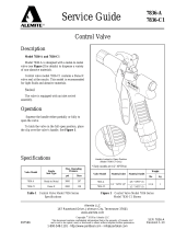
Figure 1 Oil control handle and
mechanical meter (Model 3575-A shown)
Part number Description
3575-A Quarts meter with rigid extension
3575-B Quarts meter with flexible extensions
3575-C Liters meter with rigid extension
3575-D Liters meter with flexible extension.

Initial Release 10-15 Alemite, LLC
Mechanical Meter Oil Control Handle
SER 3575A
2
Assembly
Use Teflon tape (or suitable thread sealant)
when connecting the oil control handle to an
oil hose.
Outlet Nozzle
The outlet nozzle can be fitted either “in
line” (forward) or on the outlet port “pistol
style” located under the handle.
The long outlet tube should be used for the
“in line” option.
The short adaptor (44) should be used with
the outlet nozzle assembly (50) taken off the
long outlet tube when using the “pistol style”
option (see fig. 2).
!
Notice
Do not strike oil control handle
if it fails to operate. Refer to trouble-
shooting guide or return unit to nearest
authorized service center.
Before each use check all hoses for
signs of wear, leaks or loose fittings.
Tighten all fluid connections regularly
and replace weak or damaged hoses.
Before attempting any repairs or
maintenance of product disconnect air
supply from oil pump, release oil line
pressure by pressing lever on oil control
handle.
Figure 2
Control meter showing three alternate
pistol-style configurations
!
Notice
Use threaded plug supplied to
seal outlet port not in use.
Operation
To latch the handle first press the lever (40)
followed by push button (37). To release latch
simply press and release lever (40).
The top accumulative register will record
the total volume of oil passed through the me-
ter. The bottom register is a reset-able batch to-
tal, which can be reset by pressing the reset
button.
Maintenance
Do not perform maintenance with air
supply connected.
Do not perform maintenance with fluid
inside handle under pressure.
Failure to comply may result in minor or
moderate injury.
Inspect your oil control handle daily for any
signs of damage.
Replace any damaged parts or components as
required.
Control Handle
Disassembly
Use a clean bench to carry out maintenance.
1 Remove the oil hose from the control handle
inlet swivel (33).
2 Unscrew and remove swivel (33) washer
(32) and O-ring (31) from the control han-
dle inlet. Clean or replace the strainer (35)
and O-ring (34).
3 Slide off the handle sleeve (27).
4 Remove valve spring (30), valve seal as-
sembly (29) and plunger (28).
Caution
Outlet Nozzle Operation
When fluid flows through the handle the
outlet nozzle will automatically open. When
the fluid flow stops the outlet nozzle will auto-
matically shut.
50
44
42

Initial Release 10-15Alemite, LLC
Mechanical Meter Oil Control Handle
SER 3575A
3
Caution
Maintain control of swivel. Swivel is un-
der spring tension.
Failure to comply may result in minor or
moderate injury.
!
Notice
Install spring, small end first.
!
Notice
After assembly ensure handle
latch operates correctly.
!
Notice
Cut out section in middle of
valve cam (24) must face inlet swivel
(33).
!
Notice
Lightly lubricate the valve cam
(24) before assembly.
!
Notice
End hole in plunger must face
meter.
2 Place O-Ring (23) onto valve cam (24).
3 Replace the valve cam (24) into the body
(26). Note the orientation shown on the as-
sembly drawing. Fit the second O-Ring (25)
and backup ring (22).
4 Slide lever assembly (40) into position and
replace the two Allen screws (36). (Use
thread locker or similar sealant).
5 Replace plunger (28).
6 Assemble the valve seal assembly (29), and
spring (30) then replace into the handle
body.
Lever And Valve
Removal
1 Using a 2.5 mm Allen key, remove the 2
handle screws (36).
2 Remove lever (40).
3 Remove the backup ring (22), O-Ring (23),
then push the valve cam (24) from the han-
dle body (26), and remove O-Ring (25).
Control Handle
Reassembly
1 Clean and inspect all parts. Replace any sus-
pect, worn or damaged components.
7 Replace handle sleeve (27).
8 Replace washer (32), O-ring (31) swivel as-
sembly (33) and screw firmly into place
(Use thread locker or similar sealant).

Initial Release 10-15 Alemite, LLC
Mechanical Meter Oil Control Handle
SER 3575A
4
Meter Disassembly
1 Remove rubber boot (1).
2 Unscrew the 4 x Phillips head screws (7),
from the underside of the handle body (26)
and remove register assembly (4).
3 Using 4 mm Allen key remove 4 screws
(43) from the underside of the handle body
(26).
26
19
20
Figure 3 Correct rotor position
!
Notice
Refer to Meter Disassembly Parts A and B.
!
Notice
Use all new parts when reas-
sembling the gear and shaft assembly.
!
Notice
Gears are marked in order of
assembly 1, 2 and 3.
Gear shaft (12) on register housing as-
sembly (23), must be located through
gear 2 (16) inside gearbox and fitted into
location hole in gearbox housing (18).
!
Notice
Check correct operation of rotors by
latching lever and apply low pressure
air into oil inlet. Meter should register
flow.
!
Notice
Clean all components prior to
assembly.
!
Notice
Turn rotors by hand to confirm
correct assembly. If rotors do not turn
freely. (refer to fig 3 for correct rotor
position).
!
Notice
Take care when removing reg-
ister housing as the outlet shaft (12) and
assembly are also removed.
5 Remove facia (2).
5 Replace register housing assembly (6) on
top of gearbox housing assembly (18).
6 Replace 4 Allen head screws (43) and screw
the meter assembly together.
7 Fit bevel gear (5) inside the register housing
(6).
8 Fit register assembly (4) into register
housing (6) and replace 4 x Phillips head
screws (7).
4 Remove register housing (6) assembly.
5 Remove gearbox housing (18) assembly.
6 Remove rotors (19, 20).
7 Clean and inspect all parts. Replace any sus-
pect, worn or damaged parts.
Gear and O-Ring
replacement (register
casting)
1 Pull bevel gear off the shaft (5) from inside
register housing (6).
2 Remove gear (13), circlip (11), washer (10),
O-Ring (9) and shaft (12) from the under-
side of register housing.
3 Assembly is a reversal of disassembly.
Facia Replacement
4 Remove register assembly (4) and remove
the register bracket clip (3).
6 Assembly is a reversal of disassembly.
Meter Reassembly
1 Replace rotors (19, 20) into body casting
(26) (see fig 3 for correct positioning).
2 Fit O-Ring (21) to the handle body (26).
3 Fit gears (15,16,17) into gear box (18).
4 Replace O-Ring (14) on gear box housing
(18) and position gearbox assembly on top
of handle body (26).

Initial Release 10-15Alemite, LLC
Mechanical Meter Oil Control Handle
SER 3575A
5
Figure 4 Model 3575 Series Control Handle (Exploded view)

Initial Release 10-15 Alemite, LLC
Mechanical Meter Oil Control Handle
SER 3575A
6
Spare Parts List
Item
no.
Part
no.
Description Quantity
Item
no.
Part no. Description Quantity
1 393814-7 Mechanical Boot (STD) 1 25 O-ring
1)2)
1
2 Fascia (Liters) 1 26 Body, Handle 1
2 Fascia (Quarts) 1 27 Sleeve, Handle 1
3 Bracket Clip, Register 1 28 Plunger
1)
1
4 393814-6 Register Assembly 1 29 Seal
1)2)
1
5 Gear, Bevel (Quart/Liter)
1)
1 30 Spring, Valve
1)2)
1
6 Housing, Register 1 31 O-ring
1)2)3)
1
7 Screw
1)
4 32 Washer
1)2)3)
1
8 Boss, Brass
1)
1 33 393814-3 Swivel (NPT)
3)
1
9 O-ring
1)
1 34 O-ring
1)2)3)
1
10 Washer
1)
1 35 Strainer
1)2)3)
1
11 E-Clip
1)
1 36 Screw, Countersink
1)2)
2
12 Shaft, Outlet 1 37 Button, Push 1
13 Gear L4 (Liter) 1 38 Button, Spring
1)
1
13 Gear Q4 (Quart) 1 39 Trigger Guard 1
14 O-ring
1)
1 40 Lever, Latching 1
15 Gear L3 (Liter) 1 41 Plug, Lever
1)
1
15 Gear Q3 (Quart) 1 42 Plug, 3/8” 1
16 Gear L2 (Quart), 2 Liter 1 43 Screw
1)
4
17 Gear L1 (Quart), 1 Liter 1 44 Adaptor (Pistol Style) 1
18 Housing, Gearbox 1 45 Extension, Flexible
5)
1
19 Oval Gear and Pinion 1 46 Adapter
4)
1
20 Gear, Oval 1 47 Olive
4)
1
21 O-ring1) 1 48 Compression Fitting
4)
1
22 Ring, Backup
1)2)
1 49 Extension, Rigid
4)
1
23 O-ring
1)2)
1 50 Outlet Nozzle Assembly
4),5)
1
24 Cam, Valve
1)2)
1
Repair kits
Part no. Note Description Notes
393814-1
1)
Kit, Major Service
Includes items on Figure 4.
393814-2
2)
Kit, Valve Service
393814-3
3)
Kit, Swivel Assembly (NPT)
393814-4
4)
Kit, Rigid Extension
393814-5
5)
Kit, Flexible Extension

Initial Release 10-15Alemite, LLC
Mechanical Meter Oil Control Handle
SER 3575A
7
Troubleshooting
Specifications
Trouble Cause Solution
Meter not accurate Flow rate not correct Adjust flow rate to 1-30 l/min (0.26 – 8 US gal/min)
No fluid passing through the meter
a) Blocked strainer a) Clean or replace strainer
b) Dirt particles jamming the rotors
b) Dismantle meter assembly and clean (refer to meter
disassembly)
c) Damaged plunger seal c) Replace damaged plunger seal
The meter is not registering fluid
output
a) Damaged register assembly (4) a) Replace register assembly
b) Damaged gear or gears (5,13,15,16, 17)
b) Replace complete gear set, also replace (12) shaft
and (9) O-ring.
Constant oil leak from the nozzle Damaged plunger seal (29) Replace plunger seal (check for damage)
Intermittent drip from the nozzle
particles, replace if necessary.
Dirt in the nozzle (50) Remove the nozzle and blow out any dirt
Oil leak from the lever assembly area Damaged o-rings (23, 25) Replace damaged o-rings
Oil leak from between the body handle
and housing gear box
Damaged o-rings (21) Replace damaged o-rings
Low flow rate Blocked strainer (35) Replace strainer
Oil leaking from the swivel inlet Damaged o-ring or swivel Replace swivel
Accuracy + - 1% (of Reading) Swivel Inlet 1/2” NPT
Flow Range 1-30 l/min (0.26 – 8 US gal/min) Outlet 3/8”
Operating Pressure 0-13.79 Bar / 0-3447 kPa / 0-200 PSI
Operating Temperature: -10 to 55 °C (14 to 131 °F)
Maximum Pressure 103.50 BAR / 10350 kPa / 1500 PSI
Pressure Loss
1Bar/ 100 kPa / 14.4 PSI @ 12 l/min (3.2 US)
gal/min) with calibration fluid (6 Centipoise
Viscosity) without extension
Wetted Parts: Aluminium, Acetal, Steel, Nitrile Rubber
Weight 1.16 kg ( 2.55 lbs) Fluid Compatibility:
Engine Oil, Diesel Oil, Automatic
Transmission Fluid, Anti-freeze / Anti-Boil
Mixture. (Maximum Viscosity SAE140)
Dimensions:
25.8 cm (10 inch) Long x 9.5 cm ( 3.7 inch)
High, x 11 cm (4.33 inch) Wide (Dimensions
without extension)

Initial Release 10-15 Alemite, LLC
Mechanical Meter Oil Control Handle
SER 3575A
8
Bob Hoeer
Robert Hoefler
Director Product Development and Product Engineering
St. Louis, MO
J U
U
/