Page is loading ...

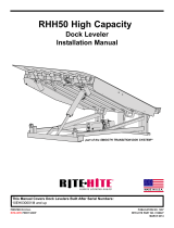
RHJ50 Jumbo
Dock Leveler
Installation Manual
PRINTED IN U.S.A.
RITE-HITE PRINT SHOP
PUBLICATION NO. 1289
RITE-HITE PART NO. 0128929
SEPTEMBER 2012
part of the SMOOTH TRANSITION DOK SYSTEMTM
This Manual Covers Dock Levelers Built After Serial Numbers:
10EH060001M and up
MADE IN U.S.A.

2Pub. No. 1289 - September 2012
RITE-HITE®RHJ50 Jumbo Dock Leveler Installation Manual
TABLE OF CONTENTS
NOTICE TO USER . . . . . . . . . . . . . . . . . . . . . . . . . . . . . . . . . . . . . . . . . . . . . . . . . . . . . . . . . . . . . . . . . . . . . . . . . .2
SAFETY WARNINGS . . . . . . . . . . . . . . . . . . . . . . . . . . . . . . . . . . . . . . . . . . . . . . . . . . . . . . . . . . . . . . . . . . . . . . . .3
PIT DETAILS . . . . . . . . . . . . . . . . . . . . . . . . . . . . . . . . . . . . . . . . . . . . . . . . . . . . . . . . . . . . . . . . . . . . . . . . . . . . . . .6
INSTALLATION INSTRUCTIONS . . . . . . . . . . . . . . . . . . . . . . . . . . . . . . . . . . . . . . . . . . . . . . . . . . . . . . . . . . . . . . .8
ELECTRICAL INSTALLATION . . . . . . . . . . . . . . . . . . . . . . . . . . . . . . . . . . . . . . . . . . . . . . . . . . . . . . . . . . . . . . . .12
ELECTRICAL SCHEMATIC . . . . . . . . . . . . . . . . . . . . . . . . . . . . . . . . . . . . . . . . . . . . . . . . . . . . . . . . . . . . . . . . . .14
HYDRAULIC SCHEMATIC . . . . . . . . . . . . . . . . . . . . . . . . . . . . . . . . . . . . . . . . . . . . . . . . . . . . . . . . . . . . . . . . . . .15
LUBRICATION CHART . . . . . . . . . . . . . . . . . . . . . . . . . . . . . . . . . . . . . . . . . . . . . . . . . . . . . . . . . . . . . . . . . . . . . .17
LEVELER ADJUSTMENTS . . . . . . . . . . . . . . . . . . . . . . . . . . . . . . . . . . . . . . . . . . . . . . . . . . . . . . . . . . . . . . . . . .18
HYDRAULIC VALVE ADJUSTMENTS . . . . . . . . . . . . . . . . . . . . . . . . . . . . . . . . . . . . . . . . . . . . . . . . . . . . . . . . . .19
STANDARD WARRANTY . . . . . . . . . . . . . . . . . . . . . . . . . . . . . . . . . . . . . . . . . . . . . . . . . . . . . . . . . .BACK COVER
PRODUCT SPECIFIC WARRANTY
RITE-HITE®warrants the RHJ50 Dock Leveler for five-years parts and one-year labor from date of shipment in
accordance with Rite-Hite's Standard Warranty Policy.
NOTICE TO USER
Your local Rite-Hite representative provides a Planned Maintenance Program (P.M.P.) which can be fitted to your
specific operation. Call your local representative or the Rite-Hite®Company, LLC at 414-355-2600.
The Rite-Hite products in this manual are covered by one or more of the following U.S. patents: 5,271,183;
5,323,503; 5,546,623; 5,553,987; 5,582,498; 5,664,930; 5,702,223; 5,762,459 (RE: 37,570); 5,882,167; 6,065,172;
6,070,283; 6,085,375; 6,092,970; 6,106,212; 6,116,839; 6,190,109; 6,220,809; 6,276,016; 6,311,352; 6,318,947;
6,322,310; 6,360,394; 6,368,043; 6,431,819; 6,488,464; 6,499,169; 6,505,713; 6,524,053; 6,634,049; 6,726,432;
6,773,221; 6,832,403; 6,880,301; 6,892,411; 7,032,267; 7,062,814; 7,134,159; 7,213,285; 7,216,391; 7,363,670;
7,380,305; 7,503,089; 7,533,431; 7,546,655; 7,584,517; 7,681,271; 7,841,823; 7,877,831; 7,823,239; 8,006,811;
8,065,770; 8,141,189 and pending U.S and foreign patent applications. RITE-HITE®, LEVEL-RITE®, THINMANTM,
SAFE-T-LIP®, HYDRACHEK®, WHEEL-LOKTM, DOK-LOK®, DUAL-DOK®, SAFE-T-STRUTTM, DOK-COMMANDER®,
JUMBOTM, HYDRA-RITETM, SAFE-T-GATE®, and SMOOTH TRANSITION DOK SYSTEMTM, are trademarks of
Rite-Hite®Company, LLC.

Pub. No. 1289 - September 2012 3
RITE-HITE®RHJ50 Jumbo Dock Leveler Installation Manual
SAFETY WARNINGS
LOCKOUT/TAGOUT PROCEDURES
The Occupational Safety and Health Administration (OSHA) requires, in addition to posting safety warnings and barri-
cading the work area (including, but not limited to, trucking office and loading docks), that the power supply has been
locked in the OFF position or disconnected. It is mandatory that an approved lockout device is utilized. An example of
a lockout device is illustrated. The proper lockout procedure requires that the person responsible for the repairs is the
only person who has the ability to remove the lockout device.
In addition to the lockout device, it is also a requirement to tag the power control in a manner that will clearly note that
repairs are under way and state who is responsible for the lockout condition. Tagout devices have to be constructed
and printed so that exposure to weather conditions, or wet and damp locations, will not cause the tag to deteriorate or
become unreadable.
RITE-HITE®does not recommend any particular lockout device, but recommends the utilization of an OSHA approved
device (refer to OSHA regulation 1910.147). RITE-HITE®also recommends the review and implementation of an entire
safety program for the Control of Hazardous Energy (Lockout/Tagout). These regulations are available through OSHA
publication 3120.
When working with electrical or electronic con-
trols, make sure that the power source has been
locked out and tagged out according to OSHA
regulations and approved local electrical codes.
XXXXXXXXXXXX
XXXXXXXXXXX
OPERATE
DO NOT
FIGURE 1 - LOCKOUT/TAGOUT
This is a statement of serious hazard. Failure to
follow the listed instructions could place the
individual at risk of serious injury or death.
This is the highest level statement. Failure to
follow the listed instructions will most likely
result in severe injury or death.
The statements used with this level of warning
deal with a safe operating procedure. If the
procedure is ignored the possibility of
personal injury may exist.
IMPORTANT is used to draw attention to a
procedure that needs to be followed to prevent
machine damage.

4Pub. No. 1289 - September 2012
RITE-HITE®RHJ50 Jumbo Dock Leveler Installation Manual
OTHER IMPORTANT OPERATIONAL SAFETY WARNINGS
Never be under the dock leveler platform or lip
without:
• Installing the Safe-T-StrutTM or other
supporting device.
• If lip needs to be extended, follow
procedures shown under Safety Devices on
the following page.
• Turning off power to the control box.
• Locking out and tagging out the main
power source, as shown under Safety
Warnings on preceding page.
Always barricade the dock leveler at ground
level and dock level from any form of traffic
when maintenance is required.
Inspect the dock leveler monthly to ensure that
there are no broken or worn parts which could
cause injury to personnel or damage to the
equipment.
• Before starting installation or maintenance,
check and follow the safety procedures of
the facility where the dock leveler is being
installed.
• Never enter a truck/trailer until its brakes are
set, air has been dumped from air ride
suspension (if applicable), and you have
visually inspected to be sure truck/trailer is
securely held in place by a vehicle restraint
or wheel chock per OSHA regulations.
• Never operate the leveler with you, anyone,
or anything on, or in front of the leveler, or
without a truck/trailer parked in position, or
from on the truck/trailer bed.
• DO NOT operate with anyone under platform
or in front of the lip.
• When leveler is not in use, always store it so
that it is supported by the lip supports and
that it is level with the surrounding dock
floor.
• If a malfunction does occur, always call your
authorized RITE-HITE®service representative
immediately.

Pub. No. 1289 - September 2012 5
RITE-HITE®RHJ50 Jumbo Dock Leveler Installation Manual
SAFETY DEVICES RITE-HITE LEVELERS
• Post warnings and barricades at dock level
and at drive level to indicate that work is
being done around and under the leveler
platform.
• Lockout/Tagout power to the leveler and post
warnings when work is being performed on
the leveler.
Never be under the dock leveler platform or lip
without:
• Installing the Safe-T-Struttm. See below right.
This can be done with the assistance of
another person by:
- Raise leveler until platform reaches its
highest position and lip extends.
Continue to maintain this position.
- Then have assistant insert the smaller end
of the Safe-T-StrutTM through the hole in
the middle of the leveler lip and place the
strut’s wider open end over the base
located on the leveler’s front frame. Align
the holes on the base and the Safe-T-
StrutTM so that the leveler may be secured
with the retaining pin and safety clip.
- Release the push button on powered
levelers allowing the Safe-T-StrutTM to rest
on the underside of the lip.
• Lockout/Tagout power supply.
- Turn off the power to the control box.
- Lockout/tagout the main power source, as
shown under Safety Warnings on the
inside front cover of this manual.
- Always barricade the leveler at dock level
and drive level to prevent any
unauthorized use of the leveler.
Remove the Maintenance Support.
• For Safe-T-StrutTM removal, have an
assistant raise the leveler to its highest
position with lip fully extended. Release the
safety clip and remove retaining pin. Lift strut
off base, and remove from lip. Return the
Safe-T-StrutTM to the proper storage position.
• If you are unable to install the Maintenance
Support properly, contact your authorized
RITE-HITE® Service Representative or RITE-
HITE® Customer Service at 1-414-355-2600.
FIGURE 2 - INSTALL SAFE-T-STRUTTM SUPPORT

6Pub. No. 1289 - September 2012
RITE-HITE®RHJ50 Jumbo Dock Leveler Installation Manual
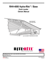
PIT DETAILS
14" Minimum Cut Back For
Retrofit And Floor
Expansion Joint
8" Pipe Bollard Minimum
From Side Dock Wall
DIM B
Pit Squaring
Dimension Reference
(See Figure 3)
104"
+1/8 / -0
4X 90°
Hold
DIM A
+1/4 / -0
52"
12" Pipe Bollard
Minimum From
Front Dock Face
1"
Max
8" Minimum
Side Wall
Cut Back For Retrofit
16"
2"
Max
8"
Pipe Bollard If Desired
If Pipe Bollards Are Used An
Additional Floor Cut Out Is
Required For Pipe Bollard.
Right Side Curb Angle
1" Rigit Conduit
(Installed By Others)
Preferred Conduit
Location 1" Conduit
(Threaded Stub End)
Alternate 1" Conduit Location
(Threaded Stub End)
Location Of Floor Cut Back For
Retrofit Installation. Expansion
Joint Grooves Or Cut In Expansion
Joints In A New Installation.
Left Side Curb Angle
Side Frames May Need
To Be Notched For 9'
Dock Door Application
Dock Face
IMPORTANT:
Angle Between Side
Curb Angles And Dock
Face Must Be Exactly 90°
8"
10"
14"
33 -1/2"
Rear Pit
Depth 14" 15" Front Wall
Dock Height Range
43" To 52" Standard
For Others Consult Factory
34"
Front Pit
Depth
10"
23"
Rear Pit Wall Must Be Plumb.
Reverse Slope Of 1/4" Is Permissible.
Front Pit Wall
Front Wall To Building Footing Reference Expansion Joint
Driveway Approach
1/2" Ref
Drainage
Pitch
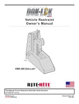
IMPORTANT NOTES PIT CONSTRUCTION:
1. Pit Construction Must Follow Instructions And Details Outlined.
RITE-HITE Corp. Will Not Be Responsible For Equipment Failure
Due To Improper Pit Construction.
2. Pit Steel Available From RITE-HITE At Additional Cost. Pit Steel
Can Be Furnished By General Contractor But Must Comply To
RITE-HITE Drawings Specifications. To Obtain Detailed Pit Steel
Drawings Contact RITE-HITE And Request Drawings.
3. Bolt Together Both Side Pit steel Frames To Front Pit Steel Then
Rear Pit Steel. Welding May Be Used In Lieu Of Bolting.
See Figure 3 on Page 8.
4. Concrete Must be 2,500 PSI Minimum.
5. Concrete Pit Must Be Continuous / Homogeneous Pour.
6. Concrete Must Be Well Vibrated Around All Pit Steel.
7. Conduit Stub Threads Must Be Completely Free Of Debris,
Upon Completion Of Pit Construction.
8. Tolerances 1/8" (Unless Otherwise Specified)
IMPORTANT:
Angle Between Side
Curb Angles And Dock
Face Must Be Exactly 90°
Rear Curb Angle
Front Curb Angle
12"
8"
2"
5"
3"
12"
7-1/2"
5"
Rebar
Rebar
SEE NOTE 3
+
-
FIGURE 3 — PIT DETAILS

Pub. No. 1289 - September 2012 7
RITE-HITE®RHJ50 Jumbo Dock Leveler Installation Manual
PIT STEEL CONNECTIONS
8"
CONDUIT LOCATION DIMENSIONS
Minimum
1" Dia.
Conduit
Required
23"
23"
16"
C
L
90°
Preferred Conduit
Location 1" Conduit
(Threaded Stub End)
Alternate 1"
Conduit Location
(Threaded Stub End)
Bolt Together Both Side Pit Steel Frames To
Front Pit Steel Then Rear Pit Steel.
Welding May Be Used In Lieu Of Bolting.
PIT DETAILS (Continued)
FIGURE 4 — ADDITIONAL PIT DETAILS
CAPACITIES F and L
NOMINAL PIT SIZES (L x W) 8’ x 8’-6” 10’ x 8’-6” 12’ x 8’-6”
PIT LENGTH DIM A 85” 109” 133”
PIT WIDTH 104” 104” 104”
PIT DEPTH DIM C 34” 34” 34”
PIT SQUARING DIM B 134-5/16” 150-5/8” 168-13/16”
PIT STEEL KIT PART # 116777 116778 116779
NOTE
Pit steel is available through RITE-HITE. Pit steel can be furnished
by general contractor, but must comply to RITE-HITE drawing
specifications. To obtain detailed pit steel drawings contact your
local representative or RITE-HITE Applications Dept. and request
drawings. Use the correct pit steel kit part number above to request
detailed drawings.

8Pub. No. 1289 - September 2012
RITE-HITE®RHJ50 Jumbo Dock Leveler Installation Manual
PREPARATION PRIOR TO INSTALLATION
1. Check pit to be sure it meets RITE-HITE pit
drawings. See Figure 3 on page 6 for details.
2. All Pit Angles must be 4 x 4 x 1/4" minimum. This
includes pit steel and concrete pour joints. If the pit
has no Front Pit Angle or a 3 x 3 x 3/16" Front Pit
Angle, contact RITE-HITE applications department.
3. Weld steel together as shown in figure 7 on page
10.
4. Leave shipping banding on until instructed to
remove it.
5. Verify that the control box voltage (inside door)
matches the leveler pump motor voltage (recorded
on Rear Frame Angle and Motor Plate).
INSTALLATION INSTRUCTIONS
1. Tack weld Weatherseal channel (if shipped loose) to
either the Toeguard or the Side Pit Angle. See
Figure 5 for details.
2. Verify that all pit steel connection joints are welded.
See Figure 7 on page 10.
INSTALLATION INSTRUCTIONS
3/8”
Center Only
End Only
End Only
.12 .50
.12 .50
.12 .50
.12 .50
Between Center
And End Welds
Hold This End Flush
With Front Edge And
Tight Against Side
Pit Angle
Side Pit Wall
IMPORTANT:
DO NOT Burn Through
Channel When Welding
To Side Pit Angle
WEATHERSEAL TO SIDE PIT ANGLE
Center Only
End Only
End Only
.12 .50
.12 .50
.12 .50
.12 .50
Between Center
And End Welds
Hold This End Flush
With Front Edge And
Tight Against Platform
Integral Toeguard
IMPORTANT:
DO NOT Burn Through
Channel When Welding
To Integral Toeguard
WEATHERSEAL TO TOEGUARD
(Factory Installed)
FIGURE 5 — TACKWELD WEATHERSEAL
• Make sure leveler power is disconnected
(locked out and tagged out according to OSHA
regulations and approved local codes) before
performing any welding on the leveler.
• DO NOT position the leveler on its side or turn
the leveler top side down at any time.
Follow these precautions when installing your
hydraulic leveler.
• ALWAYS ground to the Frame or Front Pit
Angle when welding. DO NOT have any
electrical circuit ground wires connected
when welding.
• Check motor rotation by pressing and
releasing the PLATFORM RAISE button. If the
leveler does not raise, but the motor runs, the
motor leads may be reversed. To correct,
reverse any two of the T1, T2 or T3 leads in the
junction box. DO NOT run the motor in reverse
for extended periods of time as it will damage
the hydraulic pump.
Always barricade dock leveler at ground level
and dock level before performing installation.
NOTE
Move ground to platform to prevent
arcing when welding to platform.

Pub. No. 1289 - September 2012 9
RITE-HITE®RHJ50 Jumbo Dock Leveler Installation Manual
3. Before placing leveler in pit, tack weld Installation
Tabs onto Rear Frame Angle as shown in Figure 6
(if unit is already in pit, raise leveler sufficiently to
attach Installation Tabs and lower back into pit).
4. Move 2X Filler Bars from top of rear frame, locate
and weld to ends if rear frame 3/16” to 1/4” below
top of rear frame.
NOTE
Tabs are designed to support the back edge of the
leveler and to align it with the curb steel during
installation. Make sure tabs are absolutely level with
the leveler deck.
5. Install leveler using front fork pockets or hoist
leveler into pit with four point chain assembly. Lower
leveler until it rests on the Installation Tabs. See
Figure 6.
NOTE
If placing with chains, once installation tabs are one
inch on rear pit steel set leveler down into pit and
remove rear chains. Pick up leveler slightly and
slide back until tight against rear pit steel.
INSTALLATION INSTRUCTIONS (Continued)
SECTION A-A
A
A
LIP NOT SHOWN
FOR CLARITY
Dock Face
Front Pit Angle
MUST BE 4" x 4" x 1/4" Min.
Balance Unit Using
Cheater Hooks If
Necessary
Rear Pit Angle
Side Pit Angle Pit Floor
Pit Side View
Top Of
Leveler
Shipping
Bands
Front Fork Pockets:
Hook Chain Here
Behind Lip As Shown
2x
1/4"
1/4"
Front Frame Channel
NOTE
Leveler Can Be Placed
By Lifting With A Forklift
Or 4pt Chain Lift Using
Another Device.
2x
1/4"
Filler Bar
From Top
Of Frame.
3/8"
8"
1"
3"
2x Remove Filler
Bar And Weld To
End Of Frame.
Transition
Plate
Impact
Block
Lifting
Hook
FIGURE 6 — LEVELER INSTALLATION

10 Pub. No. 1289 - September 2012
RITE-HITE®RHJ50 Jumbo Dock Leveler Installation Manual
6. Center leveler in pit side to side with rear frame
angle in contact with rear pit angle. See Figure 7.
7. Raise front of leveler to be flush with dock floor.
Support frame and insert shims (cut shipping bands
if required to install shims) under Lip Supports and
under Cylinder Clevis. For SAFE-T-LIP levelers,
measure distance from lip to lip support on each
side of leveler. Distances must match within 1/8”.
Adjust position of frame if necessary. Tack weld
shims in place. See Figure 8 on page 11.
8. Weld all stacked shims together at front of leveler.
Weld shim stacks to Front Frame Angle and to the
Front Pit Angle. See Figure 8 on page 11.
NOTE
If no shimming was required at the front of the
leveler, a minimum of eight inches (8") of weld is
required at the Cylinder Clevis and six inches (6”) of
weld under each lip support.
9. Remove shipping bands and mechanically raise
leveler platform and extend the lip completely.
Engage SAFE-T-STRUT and secure with retaining
pin.
10. Place shims at rear of leveler under Support Posts.
See Figure 8 on page 11.
11. Weld all stacked shims together at rear of leveler.
Weld all shim stacks to Frame. See Figure 8 on
page 11.
12. Stitch weld the rear frame angle of the leveler to the
rear pit angle. Place a 6" weld centered on each
hinge/support post on the leveler frame. See Figure
8. Remove installation tabs and grind clean.
Equal Gaps Must Be
Maintained On Each
Side Of The Leveler
Entire 11" Length On Each
End Must Be In Full Contact
With Pit Angle Or Shimmed
Shim Gap Between
Rear Frame Angle
And Rear Pit Angle
Between Hinge
Support Posts And
Remaining 11" At
The End Of The Frame
At Least One Side Of The
Frame Must Be In Contact
With Rear Pit Angle
Rear Edge Welding
Equal Gaps Must Be
Maintained On Each
Side Of The Leveler
Behind Hinges
And Center
Support
Per Stencil
.38" 6"
.38" 11"
.38" 5"
Each
End
Each
End
Rear Edge Shimming
FIGURE 7 — INSTALLATION DETAILS
INSTALLATION INSTRUCTIONS (Continued)
Cover the main cylinder with a fire retardant
material, such as a leather welding apron, prior
to welding near the Cylinder Clevis.
DO NOT connect any electrical circuit ground
leads until all welding is completed.
Shipping bands are under tension. Stand to one
side when cutting to avoid being cut by the
bands.

Pub. No. 1289 - September 2012 11
RITE-HITE®RHJ50 Jumbo Dock Leveler Installation Manual
13. Place shims, if required, at rear of bumper brackets
and anchor to pit floor. Verify 1/8 inch gap between
bumpers and front header. See Figures 8 and 9.
14. Clean and paint all welds and grind marks.
15. Install Weatherseal in channel. See Figure 8.
Torque Anchors
60 Ft./Lbs.
Gap (1/8” Minimum)
SIDE VIEW
TOP VIEW
Add Or Remove
Shims Behind Pad
If Needed
Shims
FIGURE 9 — BUMPER INSTALLATION
INSTALLATION INSTRUCTIONS (Continued)
TOP VIEW
OF PIT
(Without Leveler)
SIDE VIEW
Shims
NOTES:
If No Shimming Is Required At Front
Frame Angle, A Minimum Of 8" Long
x 3/8" Fillet Weld Is Required Between
The Front Frame Angle And The Front
Curb Angle Centered About The Centerline.
All Welds Are 3/8" Minimum, Unless
Otherwise Specified.
* Height Dependant On Pit Depth
Weld 8 Shims Under
Support Posts.
Shim Size: 3" x 4" x Height*
Rear Pit Angle
Typ. (2)
Places
™
Under SAFE-T-STRUT
Side Pit Angle
(5 Shim Packs)
Weld Full Face Directly
Beneath Lip Keepers
And Cylinder Clevis.
Shim Size: (2) 3" x 4" x Height*
(3) 3" x 8" x Height*
Rear Bumper Bracket Shims
(3) 3" x 4" x Height*
Rear Bumper Bracket Shims
(3) 3" x 4" x Height*
Weatherseal
Channel
WEATHERSEAL INSTALLATION
REAR SHIM PLACEMENT
FIGURE 8 — SHIM PACK LOCATIONS
Verify proper hydraulic fluid level before
operating leveler by checking decal on the side
of the tank. When adding oil, use only
manufacturer approved hydraulic oils. Consult
your authorized RITE-HITE service
representative or call RITE-HITE customer
service at (800) 456-0600.
FIGURE 10 — HYDRAULIC FLUID LEVEL INDICATOR
NOTE
With the leveler in its stored position a gap of at
least 1/8 inch must be maintained between
bumper pad and front header. When pushed by
hand the bumper must contact the front header.

12 Pub. No. 1289 - September 2012
RITE-HITE®RHJ50 Jumbo Dock Leveler Installation Manual
CONTROL BOX AND CONDUIT
INSTALLATION PROCEDURES
1. Install the control box on a wall adjacent to the over-
head door at approximately 48" above the floor
level. See Figure 11.
2. Drill a hole for the power supply conduit (by others)
in the bottom of the control box. All holes drilled
through the control box must be through the
bottom of the box.
ELECTRICAL INSTALLATION
Connect wiring as indicated by the Wiring Diagrams and
Schematics see page 14.
Incoming three phase power must connect into terminals
L1, L2, and L3. Ground must attach to the ground lug.
INSTALLATION INSTRUCTIONS (Continued)
When working with electrical or electronic
controls, make sure that the power source has
been locked out and tagged according to OSHA
regulations and approved local electrical codes.
• When drilling holes in the box, do not allow the
drill to go too deeply into the box. Damage to
the control systems may occur.
• DO NOT turn control box upside down to drill
any access holes. Cover internal electrical
components prior to drilling - this will prevent
debris from contacting the internal electrical
components potentially causing failure or
severe equipment damage.
• Remove all debris from box using a shop
vacuum. NEVER use air to blow debris from
the control box.
• The control box and all wiring should be
installed by a qualified electrician in
accordance with all national and local
electrical codes.
• If rigid conduit is installed, bonding must be
maintained between conduit connections by
using ground bushings and a jumper wire.
Minimum Wire Size Chart for Various Line Lengths and Line Loads
Line Length ( In Feet )
0-50 51-100 101-150 151-200 201-250 251-300 301-350 351-400
208-240/3 1HP 14 14 12 12 10 10 10 8
380-415/3 1HP 14 14 14 14 14 14 14 14
440-480/3 1HP 14 14 14 14 14 14 14 14
575-600/3 1HP 14 14 14 14 14 14 14 14

Pub. No. 1289 - September 2012 13
RITE-HITE®RHJ50 Jumbo Dock Leveler Installation Manual
WIRING DIAGRAM
Customer
Load Center
1/2" Conduit
Minimum
Branch Circuit
Disconnect
To
Dock
#1
To
Dock
#2
To
Dock
#3
1/2" Conduit
Minimum
1" Conduit
Minimum
Control Box
48"
Hydraulic Power Unit
(Under Leveler)
Pit Junction Box
(Recommended Location)
Pit Junction Box
(Alternate Location)
Wire Harness
(3/4" Flexible Liquidtite Conduit)
TYPICAL ELECTRICAL INSTALLATION
Voltage & Phase
Leveler
Motor Full Load Amps
Branch Circuit Disconnect
Fusing Required
208/240V (3 Phase)
380V (3 Phase)
480V (3 Phase)
575V (3 Phase)
4.4 Amps
2.4 Amps
2.2 Amps
1.7 Amps
6 Amps
4 Amps
4 Amps
3 Amps
NOTE: Starting Inrush Amperage Typically Runs 2-3 Times Running Amperage.
NOTE: Variation Of Line Voltage Will Offset Motor Performance.
Restraint Connection
Goes Through Front
Frame Angle (If Applicable)
NOTE: Leveler and Restraint
Wires Can Be Ran
In The Same Conduit
Reference Only - See Control Box Drawing For Complete Fusing Requirements
FIGURE 11 — CONTROL BOX

14 Pub. No. 1289 - September 2012
RITE-HITE®RHJ50 Jumbo Dock Leveler Installation Manual
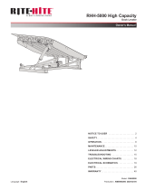
ELECTRICAL SCHEMATIC
LS2
"DOOR INTERLOCK"
CAUTION
M
G
45
78
6
9
12
T1 T2
3
T3
45
78
6
9
12
T1 T2
3
T3
45
78
6
9
12
T1 T2
3
T3
12
T1 T2
3
T3
1. REFER ALL INSTALLATION AND SERVICE TO QUALIFIED PERSONNEL.
2. INCOMING POWER FIELD WIRING - SEE MINIMUM WIRE SIZE CHART
3. POWER FROM DISCONNECT TO CONTROL BOX AND LEVELER MOTOR
FIELD WIRING TO BE MINIMUM #14GA. 60°/75°C COPPER WIRE,
INSULATED SUFFICIENTLY FOR INCOMING VOLTAGE.
4. ALL CONTROL FIELD WIRING TO BE MINIMUM #14GA. 60°/75°C
COPPER WIRE ONLY, INSULATED SUFFICIENTLY FOR INCOMING VOLTAGE.
5. ALL INTERNAL CONTROL BOX WIRING TO BE #16GA. MINIMUM, 90°C, RED
COPPER WIRE UNLESS OTHERWISE NOTED, INSULATED SUFFICEINTLY FOR
INCOMING VOLTAGE.
6. TORQUE REQUIREMENTS:
CONTACTOR: 8.9-22 LB-IN (MIN-MAX)
OVERLOAD RELAY: 16 LB-IN
GROUND TERMINAL: 35 LB-IN
TERMINAL BLOCK: 5.0-5.6 LB-IN (MIN-MAX)
7. LS1 PROVIDED BY RITE-HITE WITH LEVELER FOR ARTD.
LS2 PROVIDED BY RITE-HITE OR OTHERS FOR OVERHEAD DOOR.
8. SEE OWNERS MANUAL FOR COMPLETE OPERATING INSTRUCTIONS.
9. FUSED DISCONNECT NOTES:
- FUSED DISCONNECT IS NOT PROVIDED BY RITE-HITE PRODUCTS
CORPORATION. FUSED DISCONNECT MUST BE PROVIDED BY OTHERS AND
INSTALLED PER LATEST EDITION OF UL508A AND NEC REQUIREMENTS.
- A BRANCH CIRCUIT DISCONNECT SHALL BE LOCATED WITHIN A 50 FT.
RADIUS AND BE VISIBLE FROM THE CONTROL BOX LOCATION.
[REFERENCE LATEST EDITION OF NEC, SECTION 430]
10. LEGEND:
DENOTES WIRE CONNECTIONS THRU TERMINAL BLOCK.
DENOTES MALE/FEMALE PLUG CONNECTION
DENOTES FIELD WIRES.
DENOTES WIRE NUT CONNECTION
H4(RD)
H7(RD)H3(RD)
PB3
"LIP OUT"
6
LS1
"ARTD LIMIT SWITCH"
H7
H4
X2/N
H12
5
LIP OUT
CIRCUIT
H5A(RD)
H5 H5A
4
V
32
S1
L
1
H5C(RD)
ARTD
CIRCUIT
H2(RD) X2(WH)
H2A(RD)
H2(RD)
(14)
H3(RD)
(11)
CR1-1
PB4
"EMERGENCY STOP"
H2A(RD)
H2B(RD)
"RAISE"
(11) (14)
CR1-2
H2B(RD)
120VAC
120VAC
CR1-2
(A1)
(A1)
(A2)
(A2)
CR1-1
ESB INTERFACE RELAYS
CIRCUIT
E-STOP
LEVELER
CONTROLS
(A1)
1MCR
70VA
(96)
(95)
(A2)
1OL
JMPR
1L3
1L2
1L1
X2(WH)
X2(WH)
X2(WH)
X2(WH)
X2(WH)
H10(RD) H10 DOWN ASSIST
CIRCUIT
PB2
"DOWN ASSIST"
H5(RD)
H3(RD) H4A(RD)
PB1
H3(RD) H5(RD)
H4B(RD)
H5B(RD) 5C(RD)
H3(RD)
H3(RD)
H5(RD)
H3(RD) H3
109
108
107
106
105
104
102
103
101
100
111
110
119
122
121
120
118
117
116
115
112
114
113
FROM CUSTOMER MAIN POWER & SAFETY PROTECTION DEVICE
208-240v. 3PH. 60HZ. USE 6.0A DUAL ELEMENT TIME DELAY FUSES
380-415v. 3PH. 50/60HZ. USE 4.0A DUAL ELEMENT TIME DELAY FUSES
440-480v. 3PH. 60HZ. USE 4.0A DUAL ELEMENT TIME DELAY FUSES
575v. 3PH. 60HZ. USE 4.0A DUAL ELEMENT TIME DELAY FUSES
CONTACT BLOCK IS N.O.
WHEN E-STOP IS NOT REQUIRED
LIP OUT
SOLENOID 1
120 VAC, 0.3 AMPS
7(BK)
G
4(BLK)
X2(WH)
N.O.
12(WHT)
RT
(3)
(4)
GSHOWN WITH
DOOR CLOSED.
N.O.
TERMINAL BLOCK
JUMPER
TMR1:
SINGLE SHOT
~
(-) (+)
~
2FU1
2L1
2FU2
TRANSFORMER PRIMARY FUSING:
CLASS CC REJ DUAL ELM TD
208-240v. USE 1.0 AMP. 600v.
380-480v. USE 0.5 AMP. 600v.
575v. USE 0.4 AMP. 600v.
2L2
TRANSFORMER FOR HYDRAULIC LEVELER CONTROLS ONLY!
DO NOT USE TO POWER
AUXILIARY EQUIPMENT.
50VA
(H1) (H3) (H2) (H4)
(X2)
#12GA. MINIMUM,
GREEN
(X1)
120v.
0.5 AMP. 250v.
DUAL ELM TIME DELAY
10FU1
#16GA. MIN.,
90°C, BLACK,
COPPER WIRE
SEE NOTE 3
FUSED DISCONNECT
(BY OTHERS)
SEE NOTE 9
G
L3
L2
1FU3
1FU2
1L3
1L2
L1
1FU1
1L1
CONNECT T1, T2, T3
TO TERMINALS 1, 2, 3.
IF ROTATION IS WRONG,
REVERSE ANY 2 LINES.
T3
T2
ONE LEVELER PER OVERLOAD PROTECTION DEVICE.
[REFERENCE LATEST EDITION
OF NEC, SECTION 430]
1MCR 1OL
LEVELER MOTOR-1 H.P.
(SEE MOTOR FLA CHART)
@3450 R.P.M.
240v. 3 PH. 60 Hz.
SEE NOTE 3
T1
CONNECT T1, T2, T3
TO TERMINALS 1, 2, 3.
IF ROTATION IS WRONG,
REVERSE ANY 2 LINES.
LEVELER MOTOR-1 H.P.
(SEE MOTOR FLA CHART)
@3450 R.P.M.
380v. 3 PH. 50/60 Hz.
CONNECT T1, T2, T3
TO TERMINALS 1, 2, 3.
IF ROTATION IS WRONG,
REVERSE ANY 2 LINES.
LEVELER MOTOR-1 H.P.
(SEE MOTOR FLA CHART)
@3450 R.P.M.
480v. 3 PH. 60 Hz.
CONNECT T1, T2, T3
TO TERMINALS 1, 2, 3.
IF ROTATION IS WRONG,
REVERSE ANY 2 LINES.
LEVELER MOTOR-1 H.P.
(SEE MOTOR FLA CHART)
@3450 R.P.M.
575v. 3 PH. 60 Hz.
124
126
125
123
PLATFORM DOWN
SOLENOID 2
120 VAC, 0.3 AMPS
10(BK) X2(WH)
TO DOK-LOK CONTROL BOX FOR
RESTRAINT INTERCONNECT
(MAINTENANCE PENDANT TERMINAL)
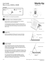
NOTE Typical Electrical Schematic Shown. Please refer to Electrical Schematics inside the dock
leveler control box for specific voltage, phase, and options ordered on your dock leveler.
FIGURE 12 — ELECTRICAL SCHEMATIC

Pub. No. 1289 - September 2012 15
RITE-HITE®RHJ50 Jumbo Dock Leveler Installation Manual
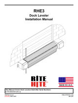
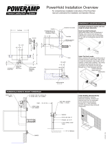
HYDRAULIC SCHEMATIC
PORT NUMBER ON
AUXILIARY MANIFOLD
OF SOLENOID ASSY.
4 WAY 2 POS.
SOLENOID VALVE
VELOSITY
FUSE
7.0 GPM
RAMP
LIFT
CYLINDER
NOTE:
A 1,450 PSI FIXED SYSTEM RELIEF VALVE WILL HAVE A 10
STAMPED ON THE SPRING RETAINING RING OF THE VALVE.
LIP
CYLINDER
ADJUSTABLE
LIP CHECK
VALVE
PILOT OPERATED
TO "OPEN"
CHECK VALVE
FIXED
ORIFICE
.060
SHUTTLE
VALVE
30 PSI
FIXED
SYSTEM
RELIEF
1,450 PSI
M
3.5 GPM
GEAR PUMP
4 WAY 2 POS.
SOLENOID VALVE
FIGURE 13 — HYDRAULIC SCHEMATIC

16 Pub. No. 1289 - September 2012
RITE-HITE®RHJ50 Jumbo Dock Leveler Installation Manual
HYDRAULIC POWER UNIT AND VALVES
HYDRAULIC PUMP SECTION VIEW
Shuttle
Valve
Solenoid Valve
115 Volt AC
2P4W Valve
Lip Extend
(Momentary Pause)
See Above
Lip Check Valve
Adjustment Screw To Lip
Cylinder
Lip Check Valve
Cap Assembly
Pilot Operated
Check Valve
Fixed System
Relief Valve
Solenoid Valve
115 Volt AC
2P4W Valve
Platform Down
To Platform Main
Cylinder Raise Port
To Platform Main
Cylinder Lower Port
TOP VIEW
FIGURE 14 — ENDHEAD SECTIONAL VIEW

Pub. No. 1289 - September 2012 17
RITE-HITE®RHJ50 Jumbo Dock Leveler Installation Manual
LUBRICATION CHART
FIGURE 15 - LEVELER LUBRICATION
Oil SAE 30 Weight
Dry Spray Lubricant
Grease
NOTE: Check Hydraulic Fluid Level.
NOTE: Inside and
under slots on
Safe-T-Lip.
NOTE: Apply grease
only if zerk fittings
are present.
NOTE: Apply
grease at zerk
fitting only.

18 Pub. No. 1289 - September 2012
RITE-HITE®RHJ50 Jumbo Dock Leveler Installation Manual
LEVELER ADJUSTMENTS
LIPSTOPBOLT
The lip stop bolt adjusts the position of the lip when
the leveler is stored to allow the lip to be centered on
lip supports when stored.
NOTE: Lip stop bolt will need to be adjusted on
longer lips to allow lip to be centered in the lip
keepers.
ARTD CAM ADJUSTMENT
NOTE: Before continuing be sure the lip stop bolt is
properly adjusted.
1. Raise leveler and install a strut securely behind the
header or mini-header to allow the lip to hang
pendant and rest against the lip stop bolt.
2. Adjust ARTD Cam.
a. Adjust collars so the front edge of ARTD cam is 1/16”
behind the centerline of the ARTD limit switch. See
figure 17.
b. Tighten front collar while holding the 1/16”
adjustment.
c. Push the rear collar forward as much as possible and
tighten. ARTD cam assembly should rotate freely.
3. Run the leveler to test the adjustment. Verify that the
lip falls a minimum of 4” before ARTD is initiated. If
not, move the cam forward slightly.
NOTE: It is not recommended to position the ARTD
cam in front of the ARTD limit switch centerline.
7/8”
Ref.
C
1/16” ARTD
Limit Switch
Rear
Collar
ARTD Cam
Front Washer
Front Collar
NOTE: There Should Be A Small Amount Of Free Movement
Between The ARTD Cam And The Rear Collar When
The Rear Collar Is Pushed Against The ARTD Cam.
This Edge Of Cam
To Be Positioned
1/16” Behind The
Center Of Roller
As Shown.
ARTD Cam Adjustment Detail
(Shown With Lip Pendant And Lip Stop Bolt Adjusted)
L
FIGURE 17 - ARTD LIMIT SWITCH
•DO NOT operate leveler with anyone standing on or
in front of the lip.
•NEVER go under the hydraulic leveler platform or lip
without installing the Maintenance Support.
•Make sure that the leveler power is locked out and
tagged out according to OSHA regulations and
approved local codes.
SAFE-T-LIPWELDED LIP
Lip
Stop Bolt
Lip In
Support
Front
Frame
Channel
FIGURE 16 - LIP STOP BOLT

Pub. No. 1289 - September 2012 19
RITE-HITE®RHJ50 Jumbo Dock Leveler Installation Manual
LEVELER VALVE ADJUSTMENTS
SHUTTLE VALVE ADJUSTMENT
(Controls Leveler Descent)
NOTE: Check oil level before making any
adjustments.
1. Leveler must be adjusted to lower, from full raised
position with lip extended to the header stops in less
than 13 to 18 seconds.
2. Remove protective cap and O-ring. Loosen locknut
without turning valve body or adjustment screw. Turn
adjustment screw to vary platform lowering speed.
Adjustments should be no more than 1/8 turn
increments.
3. Turn adjustment screw counterclockwise to decrease
the lowering speed of platform (excessive loosening
can eliminate platform lowering).
4. Turn adjustment screw clockwise to increase the
lowering speed of platform (velocity fuse may lock-up
as a result of increased platform speeds while
lowering).
5. Tighten locknut without turning valve body or
adjustment screw.
6. Reinstall o-ring and protective cap and tighten cap.
7. Re-test the unit several times to verify the setting.
LIP CHECK VAVLE ADJUSTMENT
(Controls Lip Fall Speed)
NOTE: Check oil level before making any
adjustments.
1. Leveler must be adjusted for the lip to fall in 3 to 4
seconds when the leveler is in below dock position.
2. Remove protective cap and O-ring. Loosen locknut
without turning valve body or adjustment screw. Turn
adjustment screw to vary lip fall speed. Adjustments
should be no more than 1/8 turn increments.
3. Turn adjustment screw counterclockwise to decrease
the speed the lip will extend. (If the lip does not start
or complete fall, the Lip Check Valve is set to high.)
4. Turn adjustment screw clockwise to increase the
speed the lip will fall. (If the lip falls too fast, the Lip
Check Valve setting is too low.)
5. Tighten locknut without turning valve body or
adjustment screw.
6. Reinstall o-ring and protective cap and tighten cap.
7. Re-test the unit several times to verify the setting.
•Adjustments to be completed by trained technician
only.
Shuttle Valve Body
Locknut
Cap
A
djustment
Screw
Valve Position Illustrated Represents
The Nominal Factory Setting Of 3-1/2 Turns
Out From The Fully Turned In Position
FIGURE 18 — SHUTTLE VALVE ADJUSTMENT
NOTE:
Turn In Until Adjustment Screw Bottoms Out. The
Number Of Full Turns Out Nominal Factory Settings
Are: 5 Complete Turns Out On 20" Long Lip
Screwdriver
Adjustment
Screw
Counter-
Clockwise Clockwise
Cap
Jam Nut
Exposed
Threads
NOTE:
This Lip Check Valve Has An Adjustment Range
Of 3 To 7 Complete Turns Out. Internal O-ring Seal
Holds Adjustment Screw While Locknut Is Tightened.
FIGURE 19 — LIP CHECK VALVE ADJUSTMENT

Global Sales & Service Office:
RITE-HITE
8900 N. Arbon Drive
P.O. Box 245020
Milwaukee, Wisconsin 53224
Phone: 414-355-2600
1-800-456-0600
www.ritehite.com
Representatives in all Major Cities
RITE-HITE STANDARD WARRANTY
Rite-Hite warrants that its products will be free from defects in design, materials, and workmanship for a period
of 365 days from the date of shipment. All claims for breach of this warranty must be made within 30 days after
the defect is or can, with reasonable care, be detected and in no event no more than 30 days after the warran-
ty has expired. In order to be entitled to the benefits of this warranty, the products must have been properly
installed, maintained, and operated within their rated capacities and/or specified design parameters, and not oth-
erwise abused. Periodic lubrication and adjustment is the sole responsibility of the owner. This warranty is Rite-
Hite’s exclusive warranty. RITE-HITE EXPRESSLY DISCLAIMS ALL IMPLIED WARRANTIES, INCLUDING
THE IMPLIED WARRANTIES OF MERCHANTABILITY AND FITNESS. Non-standard warranties, if any, must
be specified by Rite-Hite in writing.
In the event of any defects covered by this warranty, Rite-Hite will remedy such defects by repairing or replac-
ing any defective equipment or parts, bearing all the costs for parts, labor, and transportation. This shall be the
exclusive remedy for all claims whether based on contract, negligence, or strict liability.
LIMITATION OF LIABILITY
RITE-HITE SHALL NOT IN ANY EVENT BE LIABLE FOR ANY LOSS OF USE OF ANY EQUIPMENT OR INCI-
DENTAL OR CONSEQUENTIAL DAMAGES OF ANY KIND, WHETHER FOR BREACH OF WARRANTY, NEG-
LIGENCE, OR STRICT LIABILITY.
/