Page is loading ...

Evaluates: DS28C40
DS28C40 Evaluation System
Lite Version
General Description
The DS28C40 evaluation system (EV system) provides the
hardware and software necessary to exercise the features
of the DS28C40. The EV system consists of ve DS28C40
devices in a 10-pin TDFN package, a DS9121CQ+
evaluation TDFN socket board, and a DS9481P-300#
USB-to-I2C/1-Wire® adapter. The evaluation software
runs under Windows® 10, Windows 8, and Windows 7
operating systems, both 64- and 32-bit versions. It pro-
vides a handy user interface to exercise the features of
the DS28C40.
Features
●Demonstrates the Features of the DS28C40
DeepCover Secure Authenticator
●Logs 1-Wire/I2C Communication to Aid Firmware
Designers Understanding of DS28C40
●1-Wire/I2C USB Adapter Creates a Virtual COM Port
on Any PC
●Fully Compliant with USB Specification v2.0
●Software Runs on Windows 10, Windows 8, and
Windows 7 for Both 64- and 32-Bit Versions
●3.3V ±3% I2C Operating Voltage
●Convenient On-Board Test Points, TDFN Socket
●Evaluation Software Available by Request
DeepCover is a registered trademark of Maxim Integrated Products, Inc.
Windows is registered trademarks of Microsoft Corp.
Windows is a registered trademark and registered service mark of Microsoft Corporation.
Ordering Information appears at end of data sheet.
319-100391; Rev 0; 6/19
QTY DESCRIPTION
5DS28C40Q+ DeepCover secure authenticator
with (10 TDFN)
1 DS9121CQ+ socket board (10 TDFN)
1 DS9481P-300# USB to 1W/I2C Adapter
1 USB Type-A to USB Mini Type-B cable
EV Kit Contents
DS28C40 EV System with a USB Cable
Click here for production status of specific part numbers.

Maxim Integrated
│
2
www.maximintegrated.com
Evaluates: DS28C40
DS28C40 Evaluation System
Lite Version
Quick Start
This section is intended to give the DS28C40 evaluator a
list of recommended equipment and instructions on how
to set up the Windows-based computer for the evaluation
software.
Recommended Equipment
●DS9481P-300# USB to 1W/I2C Adapter
●DS9121CQ+ TDFN socket board
●DS28C40Q+ (five devices included)
●USB Type A-to-USB Micro-Type B cable (included)
●Computer with a Windows 10, Windows 8, or
Windows 7 operating system (64- or 32-bit) and a
spare USB 2.0 or higher port
●DS28C40 EV kit software. If needed go to the
Maxim website and search for the DS28C40 EV kit.
Click the Design Resources link. Then click the
DS28C40EVKIT Software Lite link to download the
DS28C40_Evaluation_Kit_Lite_Version_Setup_
V1_2_0.zip file or newer version software.
Note: In the following sections, EV kit software related
items are identified in bold. Windows operating system
related items are identified in bold and underline.
Hardware Setup and
Driver Installation Quick Start
The following steps were performed on a Windows 7 PC
to setup the DS28C40 EV kit hardware/software:
1) Obtain and unpack DS28C40_Evaluation_Kit_Lite_
Version_Setup_V1_2_0.zip le or newer version.
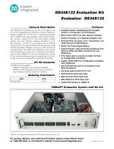
2) In a le viewer, double click on the DS28C40_
Evaluation_Kit_Lite_Version_Setup_V1_2_0 to
begin the installation.
Figure 1. File Viewer


Maxim Integrated
│
4
www.maximintegrated.com
Evaluates: DS28C40
DS28C40 Evaluation System
Lite Version
5) Click Next to install shortcuts to the default folder (Figure 4).
6) Unplug any Maxim adapter and click on Next (Figure 5) with the default settings checked. This action installs the
DS9481P-300 driver that is needed to communicate through the USB by a virtual COM port.
Figure 4. Program Shortcuts Location
Figure 5. Select to Install the Driver

Maxim Integrated
│
5
www.maximintegrated.com
Evaluates: DS28C40
DS28C40 Evaluation System
Lite Version
7) Next click on Install (Figure 6). A new window pops up to show progress of the installation.
8) Click on Next (Figure 7) when the Device Driver Installation Wizard appears.
Figure 6. Ready to Install
Figure 7. Device Driver

Maxim Integrated
│
6
www.maximintegrated.com
Evaluates: DS28C40
DS28C40 Evaluation System
Lite Version
9) Click on Finish (Figure 8) to close the nal window
conrming the driver was installed correctly.
10) Now that the driver is installed, connect the hardware
by doing the following:
a) Open the socket and insert a DS28C40 into one
of the cavities, as shown in Figure 9. Note: The
plus (+) on the package must be on aligned with
the top of the marker in the socket.
b) Close the clamshell socket.
c) Connect the DS9121CQ J2, 10-pin male plug,
into the DS9481P-300#, 10-pin female socket
(Figure 10).
d) For the DS9121CQ+, insert jumper JB1 to use
VCC (Figure 10).
e) Plug-in the DS9481P-300# using USB Type-A to
USB Micro Type-B cable into the PC.
Figure 8. Device Driver Installed Finished
Figure 9. Orientation of the DS28C40 in the Clamshell Socket


Maxim Integrated
│
8
www.maximintegrated.com
Evaluates: DS28C40
DS28C40 Evaluation System
Lite Version
12) The DS28C40 EV kit program now opens and con-
nects to the DS9481P-300 COM port. This can be
veried in the lower right corner of the window as
shown in Figure 12.
Available Options
The DS28C40 EV Kit Lite Program is designed as a
usage example to show step by step how to use the
DS28C40 device. This version includes options to write,
read, and run a compute authentication page using SHA2
or ECDSA. To access the full potential of the DS28C40,
request the full version available under NDA request.
The GUI displays all the I2C sequences for each step
performed to assist the firmware engineer.
Figure 12. DS28C40 EV Kit Program (Default View upon Opening)

Maxim Integrated
│
9
www.maximintegrated.com
Evaluates: DS28C40
DS28C40 Evaluation System
Lite Version
Usage Example—Feature Write Memory and Read Memory
1) Select the General Commands tab (Figure 13).
2) Select the Write Memory command from the combo box selection (Figure 13).
Figure 13. Selecting Command


Maxim Integrated
│
12
www.maximintegrated.com
Evaluates: DS28C40
DS28C40 Evaluation System
Lite Version
5) Click the Execute Command button (Figure 16). The I2C communication is displayed on the Log window and aids to
understand how the command is executed.
6) To perform a memory read, in the General Commands tab, select the command from the Select Command drop-
down menu (Figure 13).
7) From the Select Page drop-down menu, select the desired page to read (Figure 15).
8) Click the Execute Command button (Figure 16).
Figure 16. Execute Command

Maxim Integrated
│
13
www.maximintegrated.com
Evaluates: DS28C40
DS28C40 Evaluation System
Lite Version
Usage Example—SHA2 Compute and Read Page Authentication
1) Under the General Commands tab, in the Select Command drop-down menu, select Write Memory (Figure 13).
2) Select the Secret A or B from Select Page drop-down menu for writing (Figure 17).
3) Write the desired secret on the Page Data text box and click Execute Command button (Figure 18).
4) Select the SHA2 Commands tab.
5) Select the Compute and Read Page Authentication command from the Select Command drop-down menu
selection (Figure 19).
Figure 17. Selecting SHA2 Command

Maxim Integrated
│
14
www.maximintegrated.com
Evaluates: DS28C40
DS28C40 Evaluation System
Lite Version
Figure 19. Selecting SHA2 Command
Figure 18. Selecting SHA2 Command


Maxim Integrated
│
19
www.maximintegrated.com
Evaluates: DS28C40
DS28C40 Evaluation System
Lite Version
Usage Example—ECDSA Compute and Read Page Authentication
1) Select the ECDSA Commands tab (Figure 24).
2) From the Select Command drop-down menu, select the Generate ECC-256 Key Pair and select the desired Public/
Private Key from the Key Selection combo box (Figure 24).
Figure 24. Generate ECC Key pair

/