Page is loading ...

Evaluates: MAXM86161
MAXM86161EVSYS#
Evaluation System
General Description
The MAXM86161EVSYS# evaluation system (EV sys-
tem) allows for the quick evaluation of the MAXM86161
integrated optical module for applications at various sites
on the body, particularly in-ear and mobile applications.
The MAXM86161 device communicates using a standard
I2C-compatible interface to Maxim’s on-board MAX32664
Biometric Sensor Hub microcontroller (used for Maxim’s
algorithm evaluation) or in a pass-through mode for raw
data collection. The MAXM86161 device consists of three
optical readout channels that can be individually con-
trolled (Green, Red, and IR). The EV system allows for
flexible configurations to allow testing of various features
of the sensor. Moreover, it helps the user quickly learn
how to configure and use the MAXM86161 device.
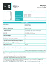
The primary EV system consists of three cir-
cuit board assemblies (MAXSensorBLE_EVKIT,
MAXM86161OSBFLEX, and the Cypress CY5677
Dongle), one USB-C to USB-A connector cable, and a
Lithium Polymer battery. These components are highlight-
ed in Figure 1 below. In addition, two programming circuit
boards (MAXM86161_MAX32630_PRGMR_ASSY, and
the MAXREFDES100HDK) and one USB-B Micro-to-
USB-A Male USB cable are provided for firmware updates
if needed.
The EV system can be powered using a USB-C supply or
LiPo Battery and comes with a MAXM86161EFD+ device
in a 14-pin OLGA package.
The MAXM86161OSBFLEX Flex-Rigid circuit board has
a Maxim Integrated MAX32664 Biometric Sensor Hub
microcontroller device installed. This Sensor Hub can
be used to implement Maxim’s HR/SpO2 Algorithm for
evaluation. The MAXM86161 GUI PC application code
that allows evaluation of both the MAXM86161EVSYS#
and the MAX32664 Sensor Hub is available in the
MAXM86161EVSYS# EV System Design Resources tab.
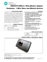
319-100382; Rev 0; 6/19
Ordering Information appears at end of data sheet.
Bluetooth is a trademark of Bluetooth SIG, Inc.
Features
●Performance Evaluation of the MAXM86161 Sensor
(e.g., SNR, Dark Current, Noise, etc.)
●Performance Evaluation of Maxim Algorithms
for Power Optimization, Heart Rate (HR), SpO2
(Peripheral Capillary Oxygen Saturation), etc. Using
the On-Board MAX32664GWEC+ Biometric Sensor
Hub Microcontroller
●Facilitates Understanding of MAXM86161
Architecture and Solution Strategy
●Real-Time Monitoring and Data Logging Capabilities
●On-Board Accelerometer
●Bluetooth™ LE for wireless data collection
FILE DECRIPTION
MAXM86161OSBFLEX.ZIP Sch, BOM, Layout
MAXSensorBLE.ZIP Sch, BOM, Layout
MAX32644FTHR.ZIP Sch, BOM, Layout
MAXM86161ADPTR Sch, BOM, Layout
MAXREFDES100HDK Sch, BOM, Layout
MAXM86161 GUI Executable PC S/W File
MAXM86161EVSYS# EV System Files
The GUI and other documentation to use this EV System
are available in the MAXM86161EVSYS# EV System Design
Resources tab and at the MAXREFDES100HDK website.
Click here for production status of specific part numbers.

Maxim Integrated
│
2
www.maximintegrated.com
Evaluates: MAXM86161
MAXM86161EVSYS#
Evaluation System
Quick Start
Required Equipment
●MAXM86161EVSYS#
●MAXM86161 EV system GUI software
●PC with Windows® OS
Procedure
1) Check that the MAXM86161OSBFLEX Board and
the MAXSensorBLE Board are connected as shown
in Figure 2 and Figure 3.
2) Connect a USB-C cable to the MAXSensorBLE
Board to power up the EV system. When powered
on, the LED toggles red and yellow.
3) Plug in the BLE dongle to an USB port on the PC.
4) Visit www.maximintegrated.com/MAXM86161EV-
SYS to download the most recent version of the EV
system software, MAXM86161GUISetupVxxx.ZIP.
Save the EV system software to a temporary folder
and uncompress the ZIP le.
Figure 1. MAXM86161 EV System Block Diagram
Windows is a registered trademark of Microsoft Corporation.

Maxim Integrated
│
3
www.maximintegrated.com
Evaluates: MAXM86161
MAXM86161EVSYS#
Evaluation System
Figure 2. Hardware Setup (MAXM86161 EV System Micro PCB)
Figure 3. Hardware Setup (MAXM86161 EV System Sensor PCB)

Maxim Integrated
│
4
www.maximintegrated.com
Evaluates: MAXM86161
MAXM86161EVSYS#
Evaluation System
5) Open up MAXM86161GUISetupVxxx.exe and follow the instructions from the pop-up windows as shown in Figure 4
to Figure 10.
Note: The BLE Dongle driver installation is completed automatically after the GUI installation.
Figure 4. Setup MAXM86161 EV System GUI Software Step 1

Maxim Integrated
│
5
www.maximintegrated.com
Evaluates: MAXM86161
MAXM86161EVSYS#
Evaluation System
Figure 5. Setup MAXM86161 EV System GUI Software Step 2

Maxim Integrated
│
6
www.maximintegrated.com
Evaluates: MAXM86161
MAXM86161EVSYS#
Evaluation System
Figure 6. Setup MAXM86161 EV System GUI Software Step 3

Maxim Integrated
│
7
www.maximintegrated.com
Evaluates: MAXM86161
MAXM86161EVSYS#
Evaluation System
Figure 7. Setup MAXM86161 EV System GUI Software Step 4

Maxim Integrated
│
8
www.maximintegrated.com
Evaluates: MAXM86161
MAXM86161EVSYS#
Evaluation System
Figure 8. Setup MAXM86161 EV System GUI Software Step 5

Maxim Integrated
│
9
www.maximintegrated.com
Evaluates: MAXM86161
MAXM86161EVSYS#
Evaluation System
Figure 9. Setup MAXM86161 EV System GUI Software Step 6

Maxim Integrated
│
10
www.maximintegrated.com
Evaluates: MAXM86161
MAXM86161EVSYS#
Evaluation System
Figure 10. Setup MAXM86161 EV System GUI Software Step 7


Maxim Integrated
│
12
www.maximintegrated.com
Evaluates: MAXM86161
MAXM86161EVSYS#
Evaluation System
7) The GUI launches with default settings as shown in Figure 12. Note that during operation, hitting the “Reset” button
restores the default settings.
8) Click on the Start button on the bottom right side to start the data acquisition.
9) Place a nger on the optical sensor.
Figure 12. MAXM86161 EV System GUI (Default)


Maxim Integrated
│
14
www.maximintegrated.com
Evaluates: MAXM86161
MAXM86161EVSYS#
Evaluation System
Figure 14. MAXM86161 EV System GUI (Accelerometer Plots)

Maxim Integrated
│
15
www.maximintegrated.com
Evaluates: MAXM86161
MAXM86161EVSYS#
Evaluation System
Detailed Description of Software
The MAXM86161EVSYS# GUI has 5 drop-down lists
(File, Device, Options, Logging, and Help) and 8 lower
tabs that are used for configuring and viewing registers
and data plots (Settings, Algorithm, PPG Plot 1, PPG
Plot 4, PPG Plot 7, PPG Plot 10, Accelerometer Plot, and
Registers).
Figure 15 below shows the 10 Configuration/Control
Groups in the Settings tab. Setting descriptions of each
group are given below.
The settings tab configures the MAXM86161 EV system
allowing capture of raw optical and accelerometer data sam-
ples. The GUI further allows for both dynamic viewing and
data logging through I2C or BLE data transfer protocols.
It should be noted that the GUI allows access to a subset
of the MAXM86161 functionality. The MAXM86161 data
sheet describes the complete set of functions supported
by the device.
Start/Stop Button
The Start Monitor button is used to start data acquisition
from the demo. The Start Monitor button is only effective
when the EV system is connected and detected. Once
Start has been pushed the Stop button appears, which
can be used to stop the acquisition. Once the acquisition
has started, all settings are locked. Terminate the acquisi-
tion to change any setting.
Reset Button
The Reset button clears out all register settings back to
the programs default settings.
Figure 15. MAXM86161 EV System GUI: Settings Tab Descriptions

Maxim Integrated
│
16
www.maximintegrated.com
Evaluates: MAXM86161
MAXM86161EVSYS#
Evaluation System
Settings Tab: PPG Conguration
Sample Rate
The sample rate can take on values between 8sps to
4096sps. The dual pulse mode option is a mode where
two led exposures are used for each time slot and aver-
aged to reduce noise. This helps achieve a higher SNR
Table 1 shows the maximum supported sampling rates (in
sps) for the MAXM86161 for the given number of expo-
sure sequences and use of accelerometer. The maximum
sample rate is limited by the BLE protocol, not the AFE
itself.
For a given sample rate, the number listed can be
increased to the next available MAXM86161 sample rate
(i.e., 500sps → 512sps).
Sample Average
The MAXM86161 has the capability to sample averaging
of 1 sample to 128 samples internally. While averaging
increases the SNR of the system, it decreases the out-
put data rate. For example, a 100sps sampling rate with
a sample average of 4, reduces the output data rate to
25sps. This mode is particularly useful for subjects who
have very low PPG signals. Averaging helps increase the
SNR; thus, enabling customers to target populations with
a lower perfusion index.
Integration Pulse Width
The pulse width setting adjusts the integration time of
an exposure. The MAXM86161 supports exposure inte-
gration times of 14.8μs, 29.4μs, 58.7μs, and 117.3μs.
The exposure pulse width is a critical parameter in
any optical measurement. Longer exposures, yielding
smaller effective noise bandwidths, result in higher SNR.
Conversely, longer exposures produce higher power
consumption compared to smaller exposures. This is pri-
marily due to the longer “on” time of the LED(s) and ADC.
The integration time is associated with a tradeoff between
higher SNR and higher power.
Burst Average Rate
When Burst Mode is disabled, PPG data conversions are
continuous at the sample rate defined by the PPG_SR
Register. When Burst mode is enabled, a burst of PPG
data conversions occurs at the sample rate defined by
the sample rate in the PPG_SR register. The number of
conversions in the burst is defined by the SMP_AVE reg-
ister. Average data from the burst of data conversions is
pushed to the FIFO at the rate of burst average rate. The
burst repeats at the rate of 8Hz, 32Hz, 84Hz, or 256Hz
can be configured in the burst average field. The burst
average rate field defines the rate at which data is pushed
into the FIFO. If the number of conversions cannot be
accommodated, the device uses the next highest number
of conversions. If the effective sample rate is too slow to
accommodate the burst rate programmed, BURST_EN is
automatically set to 0, and the device runs in continuous
mode.
Ambient Light Cancellation
The on-chip ambient light cancellation incorporates a
proprietary scheme to cancel the ambient light-generated
photodiode current, allowing the sensor to work in high
ambient light conditions.
Settings Tab: PPG Detect Conguration
PD1 ADC Full-Scale Range
The MAXM86161 PD1 channel has 4 full-scale ranges.
These ranges are 4μA (4.096μA), 8μA (8.192μA), 16μA
(16.384μA), and 32μA (32.768μA).
PD1 Bias
The PD1 BIAS values adjust the PD1_IN bias point
impedance to ensure that the photodiode settles rapidly
enough to support the sample timing. PDBIAS is config-
ured for the embedded photodiode capacitance (CPD).
For the MAXM86161, set PD Bias to 1 for the photodiode
installed in the integrated module.
Table 1. MAXM86161 Max Sample
Rates (sps)
ACCELEROMETER
# OF SEQUENCES WITH WITHOUT
1 500 1000
2 250 500
3 125 250
4 125 125
5 125 125
6 62.5 125

Maxim Integrated
│
17
www.maximintegrated.com
Evaluates: MAXM86161
MAXM86161EVSYS#
Evaluation System
Settings Tab: LED Sequence Control
FIFO Time Slots
The LED Sequence Control specifies the data acquisition
sequence that the internal state machine controller follows
and where the converted data is mapped into the FIFO.
Each FIFO field can be applied to one measurement.
Acquired data can be from LED1, LED2, or LED3 (opti-
cal exposure from LED1, LED2, or LED3) illuminated
independently. The None option terminates the sequence.
The default exposure sequence is the entry in Sequence
1 (LED1 Green), Sequence 2 (LED2 IR), and Sequence
3 (LED3 Red). This sequence repeats for each sample
instance. Note that there are 6 sequence choices and,
if they are available in the device, two photodiode selec-
tions that can potentially create 12 plots. These plots are
shown in groups of three and can be viewed under the
following tab names: PPG Plot 1, PPG Plot 4, PPG Plot
7, and PPG Plot 10.
Refer to the MAXM86161 data sheet under the FIFO
Configuration section for details.
Settings Tab: LED Driver Conguration
Each of the three LED drivers has a Range and Peak
LED current setting. There are 4 full-scale range settings
31mA, 62mA, 93mA, and 124mA. Each range has an 8-bit
current source DAC. The Peak LED Current box allows
for an actual current to be entered. The nearest available
DAC current is selected and displayed in the field.
6 LED drivers are shown, but only the first three are avail-
able for configuration.
LED Settling Time
The LED settling time is the time prior to the start of inte-
gration (pulse-width setting) that the LED is turned on.
There are four settlings, 12μs, 8μs, 6μs, and 4μs. This
time is necessary to allow the LED driver to settle before
integrating the exposure photo current.
Settings Tab: Advanced Modes
GPIO Control offers two usable configurations: 2-GPIO1
Sample Clock and 10-MAX86140/MAX861411 One Shot.
These configurations allow a user two methods of synchro-
nizing data from the accelerometer and the MAXM86161.
Settings Tab: Accelerometer Conguration
The on-board accelerometer can be enabled or disabled
by using the GUI. Supported accelerometer full-scale
ranges are ±2g, ±4g, and ±8g.
When the GPIO Control is set in either Configuration 2
or 10, the accelerometer output rate can be set. The set
values are 12.5Hz, 25Hz, 50Hz, 100Hz, 200Hz, 400Hz,
800Hz, or 1600Hz.
Settings Tab: Proximity Conguration
The optical controller also includes an optical proximity
function, which could significantly reduce energy con-
sumption and extend battery life when the sensor is not in
contact with the skin.
Refer to the MAXM86161 data sheet in the Proximity
Mode Function section for details.
Settings Tab: Picket Fence Conguration
Under typical situations, the rate of change of ambient
light is such that the ambient signal level during exposure
can be accurately predicted and high levels of ambient
rejection are obtained. However, it is possible to have
situations where the ambient light level changes extreme-
ly rapidly. For example, when a car with direct sunlight
exposure passes under a bridge and into a dark shadow.
In these situations, it is possible for the on-chip ambient
light correction (ALC) circuit to fail and produce an erro-
neous estimation of the ambient light during the exposure
interval. The optical controller has a built-in algorithm
called the picket fence function that can correct for these
extreme conditions.
Refer to the MAXM86161 data sheet under Picket Fence
Detect-and-Replace Function section for details.
Settings Tab: Supply Current
The supply current window shows the average current
being drawn from the AFE and the LEDs independent of
each other.

Maxim Integrated
│
18
www.maximintegrated.com
Evaluates: MAXM86161
MAXM86161EVSYS#
Evaluation System
Figure 16. MAXM86161 EV System GUI: Available Algorithm Modes
Figure 17a. MAXM86161 EV System GUI: Algorithm Tab Descriptions

Maxim Integrated
│
19
www.maximintegrated.com
Evaluates: MAXM86161
MAXM86161EVSYS#
Evaluation System
Algorithm Tab: AlgorithmMode
Under the Algorithm tab, there are three selectable modes
available: 1) Raw Mode (default), 2) Heart Rate Mode,
and 3) SpO2 Mode (Figure 16). While in Raw Mode, the
algorithm configuration windows are not active. When a
user selects an available algorithm mode (i.e., Heart Rate
Mode or SpO2 Mode), the corresponding configuration
window is highlighted and allows the user the ability to
modify the settings.
Algorithm Tab: Heart Rate
Refer to Figure 17a.
AEC Enable
This configuration box allows the automatic exposure
control (AEC) to be Enabled or Disabled. This algorithm
feature controls the LED current, photodiode current, inte-
gration time, and number of sample averages to increase
SNR while maintaining minimal power consumption.
Motion Magnitude Threshold
This configuration box allows a user to select the motion
detect threshold level from a range of 0g to 8g of linear
acceleration in 0.1g steps. The default value is 0.1g.
Minimum PD Current
This configuration box allows a user to select the
Minimum Photodiode (PD) Current level from a range of
0µA to 32µA in 0.1µA steps. The default value is 3.0µA.
Adjust Target PD Current Period
This configuration box allows a user to select the target
photodiode (PD) current period level from a range of 0s to
65,535s in 1s steps. The default value is 1800s.
SCD
This configuration box allows a user to Enable or Disable
the skin contact detection (SCD) feature and to set the
SCD Debounce Window Size.
Figure 17b. MAXM86161 EV System GUI: Algorithm Tab Descriptions

Maxim Integrated
│
20
www.maximintegrated.com
Evaluates: MAXM86161
MAXM86161EVSYS#
Evaluation System
Debounce Window Size
This configuration box allows a user to select the
debounce window size level from a range of 0 counts to
65,535 counts in 1count steps. The default value is 50
counts.
Alogrithm Tab: SpO2
Refer to Figure 17b.
Mode
This configuration box allows a user to select the opera-
tional mode. The following modes are available:
●Continuous
●One-Shot
●Calibration
SpO2 Timeout
This configuration box allows a user to select the SpO2
timeout level from a range of 0s to 255s in 1s steps. The
default value is 120s.
AGC Enable
This configuration box allows a user to enable or disable
the automatic gain control (AGC).
AGC Timeout
This configuration box allows a user to select the AGC
timeout level from a range of 0s to 255s in 1s steps. The
default value is 30s.
Figure 18. Register Map Access
/