Page is loading ...

Evaluates: MAX31889
MAX31889 Evaluation System
General Description
The MAX31889 evaluation system (EV system) provides a
single platform to evaluate the MAX31889, a temperature
sensor with ±0.3°C accuracy. The EV system consists of
two boards connected through headers, a MAX32630FTHR
microcontroller board, and the MAX31889 EV kit board.
The MAX32630FTHR contains the firmware necessary
to use the PC GUI program and also provides power to
the MAX31889 EV kit board. The MAX31889 EV kit board
ships with jumpers preinstalled to allow quick evaluation of
the MAX31889.
Features
●Easy to Reach Test Points
●Fully Assembled and Tested
●Windows® 7, 8, and 10-Compatible Software
Ordering Information appears at end of data sheet.
319-100468; Rev 0; 11/19
Windows is a registered trademark of Microsoft Corporation.
The GUI and other documentation to use this EV System
are available in the MAX31889EVSYS# EV System Design
Resources tab.
FILE DESCRIPTION
MAX31889EVKit.exe PC GUI Program
MAX31889_EVKIT_A.zip Sch, BOM, PCB Layout
MAX32630FTHR.zip Sch, BOM, PCB Layout
MAX31889 EV System Files
MAX31889 EV System Photo
Click here for production status of specific part numbers.

Maxim Integrated
│
2
www.maximintegrated.com
Evaluates: MAX31889
MAX31889 Evaluation System
Quick Start
Required Equipment
Note: In the following sections, software-related items
are identified by bold text. Text in bold refers to items
directly from the install of EV system software. Text that
is bold and underlined refers to items from the Windows
operating system.
●MAX31889
EV kit
board
●MAX32630FTHR
●Micro USB cable
●Windows PC with USB port
●MicroSD card (optional)
●Lithium-ion battery (optional)
Procedure
The EV system is tested and ships in two pieces:
MAX31889
EV kit
board, and MAX32630FTHR.
Follow the steps below to verify board operation:
1) Plug the MAX32630FTHR into the MAX31889
EV kit
board.
2) Set the EV system hardware on a nonconductive
surface to ensure nothing on the PCBs short together.
3) Connect the EV system hardware to a PC with the
provided USB cable. Attach the Micro USB end to the
MAX32630FTHR and the other end to the PC. LED
D1 on the MAX32630FTHR begins blinking light blue.
4) Windows should automatically begin installing the
necessary device driver. Once the driver installation
is complete, a Windows message appears near the
system icon menu, indicating the hardware is ready
to use. Do not attempt to run the GUI prior to this
message. If you do, then close the application and
restart it once the driver installation is complete. On
some versions of Windows, administrator privileges
might be required to install the USB device.
5) Once the device drivers have been installed, down-
load the software from MAX31889EVSYS# EV
system Design Resources tab and extract it to a
temporary folder.
6) Open the extracted ZIP folder and double-click the .EXE
le to run the installer. If a message box stating The
publisher could not be veried. Are you sure you
want to run this software? appears, select the Yes
option.
7) When the installer GUI appears, click Next. Select
the installation paths and whether a shortcut should
be created on the desktop. When prompted, press
Install. Once complete, click Close.
8) If a shortcut was created, double-click on the shortcut to
start the GUI. Alternatively, go to Start | All Programs.
Look for the MAX31889EVKitTool folder and click on
the MAX31889EVKitTool.EXE le inside the folder.
9) When the GUI appears, the text in the right eld of
the bottom status bar displays Connected. If the GUI
displays Not Connected, ensure the ex PCB is properly
connected and power-cycle the MAX31889 EV system.
Detailed Description of Software
Software Startup
If the EV system is connected while the software is open,
the software first initializes the hardware to communicate.
The software then reads the device registers and updates
all of the associated control fields displayed on the GUI.
Once an EV system is connected, the GUI automatically
sets the device registers and begins taking temperature
measurements.
If the EV system is not connected on startup, the GUI
starts up with no devices displayed in the Devices section
of the GUI and no temperature reading in the Selected
Device section. The status bar at the bottom of the GUI
states Not Connected.
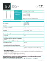
ToolStrip Menu Bar
The ToolStrip menu bar (Figure 1) is located at the top
of the GUI window. This bar comprises the File, Device,
Logging, and Help menus whose functions are detailed
in the following sections.
Figure 1. ToolStrip Menu Bar

Maxim Integrated
│
3
www.maximintegrated.com
Evaluates: MAX31889
MAX31889 Evaluation System
File Menu
The File menu contains the option to exit out of the GUI
program.
Device Menu
The Device menu provides the ability to connect or
disconnect an EV system to the GUI. If a board is disconnected
while the GUI is open, the GUI displays Hardware
Not Connected in the lower right corner. If the device
is then plugged back in, the user can navigate to the
Device menu and select Connect. If successful, the
bottom right corner of the GUI reads Device Connected.
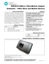
Logging Menu
The Logging menu provides two ways to export each
data sample that is being measured by the device. The
first logging option is File Logging. Selecting either log
option opens a prompt asking to select a device from
which to log data. Next, a prompt appears that allows the
user to choose a name for the comma-separated value
(CSV) log file, as well as the location to save the generated
file. Figure 2 and Figure 3 show the GUI when creating a
log file. The GUI disables file logging after one monitoring
session and a new file must be generated through the
Logging menu to log another dataset.
The second logging option is MicroSD Logging. MicroSD
logging provides the ability to operate the EV system
without a connection to a host PC or power supply. First,
insert a microSD card into the connector on the under-
side of the MAX32630FTHR. After selecting the logging
interval and writing the selection to the microSD card as
seen in Figure 4, connect a 3.7V lithium-ion (Li+) battery
with a JST PH connector to the MAX32630FTHR and
then disconnect the board from the host PC. Refer to the
MAX32630FTHR data sheet for details on connecting a
Li+ battery. Press SW2 to start saving measurements to
the SD card. Pressing SW2 again stops measurements.
To transfer the logged data from the MicroSD card to a file
on a PC, reconnect the MAX31889 EV system to the PC
and select microSD card logging from the Logging menu.
Select the Save to File option and a prompt appears
to name the log file (Figure 3). For subsequent logging
sessions, Clear Log should be pressed on the Setup
MicroSD Logging screen to prevent multiple datasets
from being recorded to the same log file.
Figure 2. Device Select Screen for Logging

Maxim Integrated
│
4
www.maximintegrated.com
Evaluates: MAX31889
MAX31889 Evaluation System
Figure 3. File Naming Screen for Logging

Maxim Integrated
│
5
www.maximintegrated.com
Evaluates: MAX31889
MAX31889 Evaluation System
Help Menu
The About option displays the GUI splash screen, which
names the GUI version being used.
Tab Control
The main interface structure of the GUI consists of a
tab control where each tab contains controls relevant to
various blocks of the device. Changing these interactive
controls triggers a write operation to the MAX31889 to
update the register contents. Likewise, these controls are
refreshed when reading from the device. The Register
Map tab allows the user to read and write to individual
registers.
General Tab
The General Tab (Figure 5) displays a general overview
of the MAX31889. The tab provides a list of devices
currently connected, temperature data for a selected
device, as well as controls for select registers.
Figure 4. MicroSD Logging Prompt
Figure 5. General Tab

Maxim Integrated
│
6
www.maximintegrated.com
Evaluates: MAX31889
MAX31889 Evaluation System
Register Map Tab
The Register Map tab (Figure 6) provides more direct
access to the internal registers of the MAX31889. From
this tab, it is possible to read the contents of individual
registers and to manually enter the desired bit settings for
a write operation. For the register address selected in the
table on the left, the contents are displayed at the bottom
of the tab and visualized as bold or non-bold bit names.
When a bit is bold, its value is 1. Otherwise, the bit is
0. Full descriptions of each bit are available in the table
on the right for quick reference. Pressing Read reads
the selected register highlighted in teal. Pressing Read
All reads all registers and updates their values in the
Register Map tab. To write to a register, set the desired
bit values by clicking on the bit names to make bold or
non-bold and then press Write.
Figure 6. Register Map Tab

Maxim Integrated
│
7
www.maximintegrated.com
Evaluates: MAX31889
MAX31889 Evaluation System
Detailed Description of Hardware
The MAX31889 EV system provides a single platform to
evaluate the functionality and features of the MAX31889.
The board contains jumpers to test the MAX31889 under
several conditions. A list of all jumpers and their respective
functions is available in Table 1.
The EV system utilizes the MAX32630FTHR Arm®
Cortex®-M4F microcontroller for wearables to interface with
the GUI and optionally provides power to the MAX31889.
The MAX32630FTHR operates either from a host PC or
directly from a Li+ battery. If an SD card is present in the
MAX32630FTHR, pressing SW2 on the MAX32630FTHR
initiates measurements and saves log files to the SD card.
Logging is stopped by pressing SW2 a second time.
Powering the EV system
The MAX31889 EV system is powered directly from the
MAX32630FTHR through either a Li+ battery or a USB
to Micro USB cable. JP1 must be connected to the 1.8V
option in order to supply power from the MAX32630FTHR.
JP2 and JP3 must each have a shunt connected to con-
nect the serial data (SDA) and serial clock (SCL) lines
from the MAX32630FTHR to the MAX31889 IC.
Note: Indicate that you are using the MAX31889 when
contacting these component suppliers.
Arm and Cortex are registered trademarks of Arm Limited (or
its subsidiaries) in the US and/or elsewhere.
#Denotes RoHS compliance.
Table 1. Description of Jumpers
SUPPLIER WEBSITE
Keystone www.keyelco.com
Maxim Integrated www.maximintegrated.com
Molex www.molex.com
Murata www.murata.com
Panasonic www.industrial.panasonic.com
Samtec www.samtec.com
Sullins www.sullinscorp.com
TE Connectivity www.te.com
PART TYPE
MAX31889EVSYS# EV System
JUMPER DESCRIPTION
JP3 Connect SCL to 4.7kΩ pullup
JP2 Connect SDA to 4.7kΩ pullup
JP1 Connect VCC to 1.8V/3.3V of the
MAX32630FTHR
Component Suppliers Ordering Information

Maxim Integrated
│
8
www.maximintegrated.com
Evaluates: MAX31889
MAX31889 Evaluation System
Other documentation to use this EV system are available in the MAX31889EVSYS# EV System Design Resources tab.
MAX31889 EV System Bill of Materials
IT EM QTY REF DES MAX INV MFG P ART # MANUFACTURER VALUE DESCRIPT ION C OMME NT S
1 1 C1 EC111000003641 GCM155L81E104KE02 MURATA 0.1UF
CAP; SMT (0402); 0.1UF;
10%; 25V; X8L; CERAMIC CHIP
2 3 GND, SCL, SDA 02-TPCOMP5006-00 5006 KEYSTONE N/A
TEST POINT; PIN DIA=0.125IN;
TOTAL LENGTH=0.35IN; BOARD
HOLE=0.063IN; BLACK;
PHOSPHOR BRONZE WIRE
SILVER PLATE FINISH;
RECOMMENDED FOR BOARD
THICKNESS=0.062IN; NOT FOR
COLD TEST
3 1 J1 01-PPPC161LFBN16P-19 PPPC161LFBN-RC SULLINS ELECTRONICS CORP. PPPC161LFBN-RC
CONNECTOR; FEMALE;
THROUGH HOLE; LFB SERIES;
2.54MM CONTACT CENTER;
STRAIGHT; 16PINS
4 1 J2 01-PPPC121LFBN12P-19 PPPC121LFBN-RC SULLINS ELECTRONICS CORP PPPC121LFBN-RC
CONNECTOR; FEMALE;
THROUGH HOLE; HEADER
FEMALE; STRAIGHT; 12PINS
5 1 J3 01-28283466P-25 282834-6 TE CONNECTIVITY 282834-6
CONNECTOR; FEMALE;
THROUGH HOLE; TERMINAL
BLOCK PCB MOUNT SIDE WIRE
ENTRY STACKING; STRAIGHT;
6PINS
6 1 JP1 01-PBC03SABN3P-21 PBC03SABN SULLINS PBC03SABN
CONNECTOR; MALE; THROUGH
HOLE; BREAKAWAY; STRAIGHT;
3PINS
7 2 JP2, JP3 01-220320212P-21 22-03-2021 MOLEX 22-03-2021
CONNECTOR; SIP; THROUGH
HOLE; MALE; STRAIGHT
THROUGH; 2PINS
8 2 R1, R2 80-004K7-Q6 ERJ-2GEJ472 PANASONIC 4.7K RESISTOR; 0402; 4.7K OHM;
5%; 200PPM; 0.10W; THICK FILM
9 3 SU1-SU3 02-JMPFS1100B-00 S1100-B;SX1100-B;
STC02SYAN
KYCON;KYCON;SULLINS
ELECTRONICS CORP. SX1100-B
TEST POINT; JUMPER; STR;
TOTAL LENGTH=0.24IN; BLACK;
INSULATION=PBT;PHOSPHOR
BRONZE CONTACT=GOLD
PLATED
10 1U1 00-SAMPLE-01 MAX31889 MAXIM MAX31889
EVKIT PART - IC; MAX31889;
+/- 0.25 DEGC ACCURATE I2C
TEMPERATURE SENSOR;
PACKAGE OUTLINE DRAWING: 21-
0164; PACKAGE LAND PATTERN:
90-0004; PACKAGE CODE: L622-1
11 3V1P8, V3P3, VDD 02-TPCOMP5005-00 5005 KEYSTONE N/A
TEST POINT; PIN DIA=0.125IN;
TOTAL LENGTH=0.35IN; BOARD
HOLE=0.063IN; RED; PHOSPHOR
BRONZE WIRE SILVER PLATE
FINISH; RECOMMENDED FOR
BOARD THICKNESS=0.062IN
12 1PCB EPCB31889 MAX31889 MAXIM PCB PCB:MAX31889 -
TOTAL 20
DO NOT PURCHASE(DNP)
ITEM QTY REF DES MAXINV MFG PART # MANUFACTURER VALUE DESCRIPTION COMMENTS
TOTAL 0
PACKOUT (These are purchased parts but not assembled on PCB and will be shipped with PCB)
ITEM QTY REF DES MAXINV MFG PART # MANUFACTURER VALUE DESCRIPTION COMMENTS
TOTAL 0

Maxim Integrated
│
9
www.maximintegrated.com
Evaluates: MAX31889
MAX31889 Evaluation System
MAX31889 EV System Schematic
Other documentation to use this EV system are available in the MAX31889EVSYS# EV System Design Resources tab.
4.7K 4.7K
VDD
282834-6
PPPC161LFBN-RC
PBC03SABN
22-03-2021
22-03-2021
VDD
0.1UF
MAX31889
PPPC121LFBN-RC
VDD
JP2
R2R1
JP1
JP3
U1
C1
SCL
SDA
GND
V3P3
V1P8
VDD
J3
J2
J1
GPIO1
GPIO0
SDA
GPIO0
SDA
SCL
GPIO1
SCL
SDA
SCL
GPIO0
GPIO1
V3P3
V1P8
1
3
2
1
21
2
6
3
2
4
1
5
6
5
4
3
2
1
12
11
10
9
8
7
6
5
4
3
2
1
16
15
14
13
12
11
10
9
8
7
6
5
4
3
2
1
VDD
GND
GPIO1SDA
SCL
GPIO0

Maxim Integrated
│
10
www.maximintegrated.com
Evaluates: MAX31889
MAX31889 Evaluation System
MAX31889 EV Kit Interface Board PCB Layout—Top Silkscreen
MAX31889 EV Kit Interface Board PCB Layout—Top View
MAX31889 EV System PCB Layout Diagrams
Other documentation to use this EV System are available in the MAX31889EVSYS# EV System Design Resources tab.
1.0’’
1.0’’

Maxim Integrated
│
11
www.maximintegrated.com
Evaluates: MAX31889
MAX31889 Evaluation System
MAX31889 EV Kit Interface Board PCB Layout—Bottom View
MAX31889 EV Kit Interface Board PCB Layout—Bottom Silkscreen
1.0’’
1.0’’
MAX31889 EV System PCB Layout Diagrams (continued)

Maxim Integrated cannot assume responsibility for use of any circuitry other than circuitry entirely embodied in a Maxim Integrated product. No circuit patent licenses
are implied. Maxim Integrated reserves the right to change the circuitry and specications without notice at any time.
Maxim Integrated and the Maxim Integrated logo are trademarks of Maxim Integrated Products, Inc. © 2019 Maxim Integrated Products, Inc.
│
12
Evaluates: MAX31889
MAX31889 Evaluation System
REVISION
NUMBER
REVISION
DATE DESCRIPTION PAGES
CHANGED
0 11/19 Initial release —
Revision History
For pricing, delivery, and ordering information, please visit Maxim Integrated’s online storefront at https://www.maximintegrated.com/en/storefront/storefront.html.
/