PAC RPK4-FD2101 User manual

Type
User manual

This manual is also suitable for

Complete Radio Replacement with
Integrated Climate Control Retention for Select
2015-2019 Ford F150 and 2017-2019 Ford Super Duty
RPK4-FD2101
© 2019 AAMP Global. All rights reserved. PAC is a Power Brand of AAMP Global.
PAC-audio.com
Pacific Accessory Corporation
Page 1
Rev: V2
Date:091319
Introduction and Features
The RPK4-FD2101 is a complete radio replacement kit with integrated climate control retention for the 2015-2019 Ford
F-150 and 2017-2019 Ford Super Duty equipped with the 8” screen. Parts are included for vehicles with multiple upper
button congurations and for vehicles with or without heated / air conditioned seats. This kit utilizes the factory HVAC
control knobs for a factory look and experience. All modules and cables are included to retain important features of
the factory system including: steering wheel mounted radio controls, factory reverse camera, 360-Degree camera, Pro
Trailer Camera, and AM/FM reception.
A secondary 5.2” LCD screen is added for additional vehicle control including: HVAC user interface retention, vehicle
settings retention, factory amplier control, settings for control of the RPK4.2-FD2101 interface, forced camera
activation, ability to add additional cameras, tire pressure and vehicle gauges. Features provided by the LCD screen
will vary based on the vehicle features. See Important Notes (next section) for additional information.
Four hard buttons added to the radio dash bezel (below the 5.2” LCD screen) allow user to set presets to control
functions including: specic HVAC controls, forced camera activation, LCD screen controls (Day Mode, Night Mode,
Display O). Options for hard buttons will vary based on vehicle features and which cameras are installed.
Some advanced features require additional accessories, sold separately.
Important Notes
We recommend reading this manual thoroughly to familiarize yourself with the entire process
prior to beginning the installation.
1. Transfer of the factory HVAC knobs and circuit board, and button panel is required. Professional installation is
recommended.
2. Only compatible in vehicles equipped with the 8” screen.
3. Installation with 2018+ F-150 models, DOES NOT retain the Bang & Olufsen factory amplier, APH-FD02 (sold
separately) can be used to bypass the amplier in these applications.
4. Installation with 2018 - 2019 Super Duty models DOES retain the Bang & Olufsen amplier.
5. Does Not Retain:
Compass that is displayed in the instrument cluster. The compass feature is lost.
Parallel park assist.
User interface for the factory massaging seats. (Massage function still available via hard button activation).
Auxiliary input jack in 2015 vehicles.
Ford’s WiFi-Hotspot.
MyKey functions that limit the radio. (Functions that limit the vehicle are retained).
Use of the radio to re-assign the door lock keypad code. (Code can still be changed via the keypad itself).
Surround Mode
Speed Compensated Volume.
6. Once the radio is removed, the chimes will play through the factory piezo speaker in the dash and not the cabin speakers.
7. Use of improper length screws during kit re-assembly can result in damage to this product. See FIG A: Actual size
reference chart.
8. If you are adding additional cameras, beyond reverse cam, PAC part number RPA-16P5V (sold separately) can be
used for up to 5 total cameras.
1:1
22mm
6mm
16mm
FIG A:
Actual Size
Complete Radio Replacement with
Integrated Climate Control Retention for Select
2015-2019 Ford F150 and 2017-2019 Ford Super Duty
RPK4-FD2101
© 2019 AAMP Global. All rights reserved. PAC is a Power Brand of AAMP Global.
PAC-audio.com
Pacific Accessory Corporation
Page 2
Rev: V2
Date:091319
Two 7mm Bolts
Remove
Grill Locking Clip Openings
Two 7mm Bolts Below Pocket
Two 7mm Bolts
Pull Pocket Straight Up and
Out to Access
Remove
Components
1
7
6
5
4
3
2
8
9
10
13
11
12
14
Tools needed for installation : 7mm socket, 10mm socket, ratchet, T10 torx screwdriver, small athead screwdriver, plastic
panel removal tool (example - PAC part number TL-PRY2).
1. (x2) Upper Dash Button Inserts
2. RP4.2-FD2101 Interface
3. Pocket (For single DIN applications)
4. (x2) Radio Brackets (left and right)
5. (x2) HVAC Trim Panel
6. LCD Display Output Connector
7. USB Extension Cable (PAC part - USB-GM1)
8. Radio Dash Bezel with 5.2” LCD Display
9. Reverse Camera Retention Harness
10. RP4.2-FD2101 Aftermarket Radio Connection Harness
11. (x6) T10 6mm screws, (x8) Phillips Head Pan Head
Radio Mounting Screws and (x8) Dash Clips
12. Rear Panel Cover
13. AM / FM Antenna Adapter (BAA22)
14. RP4.2-FD2101 Interface Harness (FD2A-RS-HAR)
Installation
Part One: Disassembly of Factory Dash
Remove the dash pocket that is at the top of the dash above the radio display.
If the vehicle does not have a center channel: Remove the the rubber mat from the pocket, remove the two 7mm bolts at
the back of the pocket, then use a plastic pry tool to pop the top pocket straight up, and out of the dash.
If the vehicle has a center channel: Use a plastic pry tool around the left and right side and front of the grill to pop the grill
straight up. There is a locking clip close to each corner of the grill. Remove the two 7mm bolts that are located at the back
of the pocket, then use a plastic pry tool to pop the top pocket straight up, and out of the dash.
Remove the two 7mm bolts that hold the radio dash panel in place that are located at the top, back side of the radio dash
panel.
Step 1
Remove Rubber Mat to
Access Two 7mm Bolts
at Back of Pocket
Grill Held in Place By 4 Pull Tabs
Pull Upwards To Release
Without Center
Channel
With Center
Channel
Complete Radio Replacement with
Integrated Climate Control Retention for Select
2015-2019 Ford F150 and 2017-2019 Ford Super Duty
RPK4-FD2101
© 2019 AAMP Global. All rights reserved. PAC is a Power Brand of AAMP Global.
PAC-audio.com
Pacific Accessory Corporation
Page 3
Rev: V2
Date:091319
Top Right
Module Bracket
Previous Camera Module
Mounting Location
Camera
Module
Lower the camera module in the dash
and place the top right mounting
bracket onto the previous bottom
stud mount, and loosely secure using
one of the factory 10mm nuts that
you removed in the previous step.
You can now secure the bottom
of the camera module by using
a zip tie or by using the fastener
of your choice. Once completed,
nish tightening the top nut from the
previous step.
Camera
Module
Top Right
Module Bracket
Top Right
Module Bracket
If vehicle is equipped with a
factory camera module, it must
be relocated. Remove the three
nuts securing it using a 10mm
socket.
Part One: Disassembly of Factory Dash (cont.)
Step 4
Step 6
Step 5
Audio Control Module
Factory Screen
Remove the factory screen / SYNC module
(attached to the screen), and Audio Control
Module (ACM) using a 7mm socket. These
parts are no longer needed. If you intend to
reinstall the factory radio later, these pieces
will need to be stored away for use at time of
reinstallation.
Step 3
The radio dash panel
(outlined in Red) can now
be removed by pulling
toward you. A plastic
pry tool can be used if
necessary.
Step 2
Complete Radio Replacement with
Integrated Climate Control Retention for Select
2015-2019 Ford F150 and 2017-2019 Ford Super Duty
RPK4-FD2101
© 2019 AAMP Global. All rights reserved. PAC is a Power Brand of AAMP Global.
PAC-audio.com
Pacific Accessory Corporation
Page 4
Rev: V2
Date:091319
Part Two: Disassembly of Factory Dash Panel
Remove the (9) T10 22mm
screws from factory dash panel.
Set the screws aside for later
use.
Remove back of factory dash panel
by releasing the 2 locking tabs on
each side. The factory rear cover
panel will not be used with the
RPK4-FD2101 installation kit.
Step 2
Remove (4) T10 16mm screws from the
upper circuit board and the (6) T10 16mm
screws from the lower circuit board. Set
the screws aside for later use.
Step 4
Dual Zone or Single Zone Climate Controls?
What type of climate controls the vehicle has determines which instructions to follow for the remainder of the disassemby of
the factory dash panel. If the vehicle has
dual zone climate controls, proceed to Section A.
If the vehicle has single zone
climate controls, jump ahead to Section B.
Dual Zone Climate Controls
Single Zone Climate Controls
Proceed to Section A
Jump to Section B
Remove the upper dash buttons from back of
the dash bezel and set aside for later use. To
release, squeeze the left and right release tabs
(on each button) inward. The buttons will come
out from the front of the dash bezel.
Depending on the trim package of the vehicle,
there will be two or three separate buttons. All
should be set aside.
Step 1
Part Two - Section A: With Dual Zone Climate Controls
Step 3
Remove the 2 ribbon cables from the
lower circuit board by sliding each
of the locking tabs away from the
connector, and carefully pulling the
ribbon cable out of the connector.
Step 5
Section A:
Section A only covers dual zone
climate controls
applications.
For single zone climate controls
applications, see Section B Factory
Dash Panel Disassembly (page 5).
(Continued Next Page)
Complete Radio Replacement with
Integrated Climate Control Retention for Select
2015-2019 Ford F150 and 2017-2019 Ford Super Duty
RPK4-FD2101
© 2019 AAMP Global. All rights reserved. PAC is a Power Brand of AAMP Global.
PAC-audio.com
Pacific Accessory Corporation
Page 5
Rev: V2
Date:091319
Remove the lower circuit board to gain access to the
temperature control and fan speed knobs, and set it
aside for later use. The temperature control and fan
speed knobs, along with the HVAC button panel, will
now be loose in the dash bezel.
Part Two: Disassembly of Factory Dash Panel (cont.)
Remove the HVAC upper circuit
board from the factory dash
bezel and set it aside for later
use.
Remove the temperature control and fan
speed knobs by pulling them out from
the back of the dash bezel, along with
the clear lighting rings (one on the left
side and one on the right side) that sit
below the knobs, and set the knobs and
light rings aside for later use.
Remove the HVAC button panel, and
set it aside for later use.
Depending on the vehicle’s options,
the panel may, or may not include
buttons for heated and air conditioned
seats.
Step 6
Step 7
Step 8 Step 9
Section A: With Dual Zone Climate Controls
Part Two - Section B: With Single Zone Climate Controls
Center the Temperature
Control Knob
Section B:
Section B only covers applications with single zone climate controls.
For applications with dual zone climate controls, see Section A (page 4).
Prior to proceeding, center the temperature control knob so that the marker
on the knob is centered between the cold and hot scales on the face of the
knob. If the knob is not centered prior to additional steps, the temperature
control knob may not be able to adjust to the full cooling or heating positions.
(Continued Next Page)
Continue
To Part
Three
Bottom
of
Page 6
Section A (cont.):
Complete Radio Replacement with
Integrated Climate Control Retention for Select
2015-2019 Ford F150 and 2017-2019 Ford Super Duty
RPK4-FD2101
© 2019 AAMP Global. All rights reserved. PAC is a Power Brand of AAMP Global.
PAC-audio.com
Pacific Accessory Corporation
Page 6
Rev: V2
Date:091319
Part Three: Assembly of Aftermarket Dash Kit
Use the previously removed HVAC button panel to determine which bottom HVAC trim panel will be used. If the additional buttons
for heated / cooled seats and fan speed are present, the trim panel with the provision for the additional buttons will be used (left
trim panel in photo). If those buttons are not present, the trim panel without the additional button provision will be used (right trim
panel in photo). Refer to part 2, step 9.
Step 1
Part Two: Disassembly of Factory Dash Panel (cont.)
Section B: With Single Zone Climate Controls
Remove the large black plastic gear
by pulling the gear straight up from the
lower circuit board, and set aside
for
later use.
Step 4
Remove (4) T10 16mm screws
from the upper circuit board and
the (6) T10 16mm screws from the
lower circuit board. Set the screws
aside for later use.
Step 5
Remove the 2 ribbon cables from the
lower circuit board by sliding each
side of the locking tab away from the
connector, and carefully pulling the
ribbon cable out of the connector.
Step 6
Remove the lower circuit board to gain access
to the temperature control and fan speed
knobs, and set it aside for later use. The
temperature control and fan speed knobs,
along with the HVAC button panel, will now be
loose in the dash bezel.
Step 7
Remove the temperature control
and fan speed knobs by pulling
them out from the back of the dash
bezel, and set aside for later use.
Remove the HVAC button
panel, and set it aside for later
use.
Step 8
Step 9
ContinueTo Part Three (Below)
Complete Radio Replacement with
Integrated Climate Control Retention for Select
2015-2019 Ford F150 and 2017-2019 Ford Super Duty
RPK4-FD2101
© 2019 AAMP Global. All rights reserved. PAC is a Power Brand of AAMP Global.
PAC-audio.com
Pacific Accessory Corporation
Page 7
Rev: V2
Date:091319
Attach the appropriate HVAC
trim panel to the back of the
RPK4-FD2101 kit using (4) of
the supplied T10 6mm screws.
Insert the HVAC knob light rings, then the
knobs (from Part - Two, Section A, Step 8)
into kit. The openings for the light rings are
shaped for the light ring to drop into place
when in the correct position. The HVAC
knobs are “keyed” for the correct position.
1:1
6mm
Part Three: Assembly of Aftermarket Dash Kit (cont.)
Step 2
Step 3
Set the previously removed
HVAC button panel in position in
the kit’s HVAC trim panel.
Step 4
Place the previously removed
HVAC lower circuit board into
position on the RPK4-FD2101 kit.
The ribbon cable locking tabs will
be on top.
Step 5
Top Board’s Two
T10 16mm
Screws Only
Make Contact
With a Small
Section of the
Board
**Screws Do
Not Go Through
Top Board**
Use (8) of the T10 16mm screws that were set aside from
disassembly step 4 (page 4) to secure the upper and lower circuit
boards to the kit. The positions for the upper circuit board screws
are in a dierent location from the OEM mounting position. On
the upper circuit board, the two screws that hold it in place only
make contact with part of the circuit board. The upper board is
further secured in later steps, once the back cover is installed.
Step 7
Dual Zone or Single Zone Climate Controls?
What type of climate controls the vehicle has determines which instructions to
follow for Steps 3 through 7 of the assembly of the aftermarket dash kit.
If the vehicle has dual zone climate controls, proceed to Section A.
If the vehicle has single zone climate controls, jump ahead to Section B.
Dual Zone Climate Controls
Single Zone Climate Controls
Proceed to Section A
Jump to Section B
Set the HVAC upper circuit
board bezel into place on the
RPK4-FD2101 kit.
Step 6
Continue
To Step
8
On
Page 9
Part 3 - Section A: With Dual Zone Climate Controls
Complete Radio Replacement with
Integrated Climate Control Retention for Select
2015-2019 Ford F150 and 2017-2019 Ford Super Duty
RPK4-FD2101
© 2019 AAMP Global. All rights reserved. PAC is a Power Brand of AAMP Global.
PAC-audio.com
Pacific Accessory Corporation
Page 8
Rev: V2
Date:091319
Set the previously removed
HVAC button panel and
HVAC knobs in position in the
kit’s HVAC trim panel.
Step 3
Verify that the temperature control knob is still
centered (see Part 2 - Section B on bottom
of page 5), then install the black plastic gear
as shown. Make sure the alignment mark on
the gear is pointing at the small gear that is
attached to the temperature control knob.
Step 7
Part Three: Assembly of Aftermarket Dash Kit (cont.)
Section B: With Single Zone Climate Controls
Place the previously removed lower
circuit board into position on the
RPK4-FD2101 kit.
Step 4
Top Board’s Two T10 16mm
Screws Only Make Contact With a
Small Section of the Board
**Screws Do Not Go Through Top
Board**
Use (8) of the T10 16mm screws that were set
aside from disassembly step 5 (page 6) to secure
the upper and lower circuit boards to the kit. The
positions for the upper circuit board screws are in a
dierent location from the OEM mounting position.
On the upper circuit board, the two screws that hold
it in place only make contact with part of the circuit
board. The upper board is further secured in later
steps, once the back cover is installed.
Step 6
Place the previously removed
upper circuit board into place on the
RPK4-FD2101 kit.
Step 5
Continue To Step 8
On
The Following Page
1:1
22mm
6mm
16mm
Complete Radio Replacement with
Integrated Climate Control Retention for Select
2015-2019 Ford F150 and 2017-2019 Ford Super Duty
RPK4-FD2101
© 2019 AAMP Global. All rights reserved. PAC is a Power Brand of AAMP Global.
PAC-audio.com
Pacific Accessory Corporation
Page 9
Rev: V2
Date:091319
Part Three: Assembly of Aftermarket Dash Kit (Sections A and B cont.)
T10 16mm
T10 22mm
Use (5) of the T10 22mm screws removed in
disassembly step 2 (page 4) and the (2) T10 16mm
screws (for the top 2 screws) left over from step 4
(page 4) to secure the back cover to the dash kit. See
FIG. A at bottom of page for screw size reference.
Single Climate Controls
Dual Climate
Controls
Rear Panel
Cover
Attach the supplied rear panel cover to the back of the
RPK4-FD2101 kit. The cover will latch into place when correctly
seated.
Step 9
Step 10
Insert the appropriate upper
dash button bezel into the RPK4-
FD2101
,
use the (2) supplied
T10 6mm screws and insert the
buttons that were removed during
disassembly (step 1 page 4). See
FIG. A on page one for screw size
reference.
Step 11
Assembled Kit
Step 12
1:1
22mm
6mm
16mm
a. b. c.
Insert the ribbon cables from the upper HVAC circuit board into the lower HVAC circuit board (upper left and right right
corners of the circuit board). The locking tabs must be in the unlocked position (tabs pulled away from the connector) in
order to seat the ribbon cables. Make sure the cables are fully inserted, then push the tabs in to secure the ribbon cables in
place.
Figure a: Locking tabs unlocked, with the ribbon cable partially inserted.
Figure b: Locking tabs unlocked, with the ribbon cable fully inserted.
Figure c: Locking tabs locked, with the ribbon cable fully inserted.
Step 8
Complete Radio Replacement with
Integrated Climate Control Retention for Select
2015-2019 Ford F150 and 2017-2019 Ford Super Duty
RPK4-FD2101
© 2019 AAMP Global. All rights reserved. PAC is a Power Brand of AAMP Global.
PAC-audio.com
Pacific Accessory Corporation
Page 10
Rev: V2
Date:091319
Mounting the Aftermarket Radio
Remove tab (LH & RH) for Double-DIN radio Install
(LH-Side bracket shown)
Mount radio to brackets using supplied screws
OR
Attach included pocket to bottom of kit brackets
Mount radio to brackets using supplied screws
Reset Button
USB Port
Radio Select
DIP switches
Interface
Connector 4
Rotary Dial
Not Used
LED 2
LED 1
Interface
Connector 1
Expansion
Port
Interface
Connector 2
Non-Amplied
Audio Output
Interface Connector 3
Amplied
Audio Output
Interface Connector 3
RP4.2-FD210101 Module Layout
Part Four: Conguring and Wiring the RadioPRO Interface
Double-DIN
Single-DIN
Remove tab (LH and RH) for Double-DIN radio
install (LH-Side bracket shown)
Mount radio to brackets using supplied screws
Attach included pocket to bottom of kit brackets
Mount radio to brackets using supplied screws
Complete Radio Replacement with
Integrated Climate Control Retention for Select
2015-2019 Ford F150 and 2017-2019 Ford Super Duty
RPK4-FD2101
© 2019 AAMP Global. All rights reserved. PAC is a Power Brand of AAMP Global.
PAC-audio.com
Pacific Accessory Corporation
Page 11
Rev: V2
Date:091319
Part Four: Conguring and Wiring the RadioPRO Interface (cont.)
Interface Connectors
White / Red HS-CAN + Input
White / Black HS-CAN - Input
Pink MS-CAN + Input
Pink / Black MS-CAN - Input
Blue / White Not Used
White* Not Used
White / Red* Not Used
* White and White / Red go to the 3
position toggle switch (not used).
Interface Connector 2
White Front L + output
White / Black Front L - output
Gray Front R + output
Gray / Black Front R - output
Green Rear L + output
Green / Black Rear L - output
Purple Rear R + output
Purple / Black Rear R - output
Ext Speaker
Out
Not Used
Interface Connector 3
Purple Rear R + input
Purple / Black Rear R - input
Green Rear L + input
Green / Black Rear L - input
Gray Front R + input
Gray / Black Front R - input
White Front L + input
White / Black Front L - input
Blue / Yellow SWC Output / Key 1
Brown SWC Output / Key 2
3.5 mm Jack SWC Output
Pink Vehicle Speed
Sense Output
Light Green Parking Brake
Output
Violet / White Reverse Signal
Output
Orange / White Illumination Output
Blue / White Amp Turn On Input
Blue Not Used
Interface Connector 4
LCD Display Output Connector
Red Aftermarket
Camera Acc 12v+
Output (800 mA)
Black Aftermarket
Camera Ground
Output
Yellow
Composite
Male
Camera Out
To Aftermarket
Radio
Yellow
Composite
Female
Camera In
From Vehicle
Connector
Reverse Camera
Retention Harness
Vehicle Connector 1
Yellow Battery +12v
Black Ground
Pink MS-CAN +
Pink / Black MS-CAN -
Blue / White Not Used
Brown / Black Center CH - input
Brown Center CH + input
White Front L + input
White / Black Front L - input
Gray Front R + input
Gray / Black Front R - input
Green Rear L + input
Green / Black Rear L - input
Purple Rear R + input
Purple / Black Rear R - input
Vehicle Connectors
White Subwoofer RCA +
Black Subwoofer RCA -
Blue / White Not Used
Vehicle Connector 2
White / Red HS CAN +
White / Black HS CAN -
Black Camera Shield
Yellow Camera +
Black Camera -
Vehicle Connector 3
Interface Connector 1
Red Accessory Output
(10A)
Yellow 12v+
Black Ground
DIP Switches
Alpine JVC
Kenwood /
Lightning Audio
Clarion /
Nakamichi
/ Stinger
2-Wire
Resistive
Pioneer /
Other*
Sony Fusion
1 2 1 & 2 3 2 & 3 1, 2, & 3 4 1 & 4
Set DIP switches that correspond with your radio to the ON position.
Set all other DIP switches to the OFF position.
*Other - Dual / Axxera (these brands could also have 2-wire resistive), Jensen, Rockford Fosgate
The radio select DIP switches on the side of the interface must be adjusted to the proper radio setting
before plugging the interface into the vehicle.
Complete Radio Replacement with
Integrated Climate Control Retention for Select
2015-2019 Ford F150 and 2017-2019 Ford Super Duty
RPK4-FD2101
© 2019 AAMP Global. All rights reserved. PAC is a Power Brand of AAMP Global.
PAC-audio.com
Pacific Accessory Corporation
Page 12
Rev: V2
Date:091319
1. Wire the aftermarket radio harness according to the wiring connections charts for
Interface Connector 1 and Interface Connector 4 provided on page 11.
2. Connect Interface Connectors 1, 2 and 4 to the RP4.2-FD2101.
3. Connect Interface Connector 3 to either the amplied or non-amplied audio
output connector depending on your scenario.
4. Connect the SWC output wire to the aftermarket radio (aftermarket radio must
support a wired remote input).
5. Once all connections have been made, plug the vehicle connectors into the
vehicle harness. It is recommended that this be done with the vehicle running.
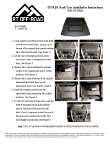
6. Reverse camera connection (see Fig. 2):
a. Connect the included RPA-16P1V harnes to the 16-pin connector (Connector
3) on the back of the radio dash bezel (see Fig.1).
b. Connect the Male Yellow RCA (Video Output) from the RPA-16P1V harness
to the aftermarket radio’s reverse camera input.
c. Connect the Female Yellow RCA (Video Input) from the RPA-16P1V harness to
the Male Yellow RCA from vehicle connector 3 (factory reverse camera), or to
the aftermarket reverse cameras RCA video output.
d. Connect the red and black power wires from the RPA-16P1V to the aftermarket reverse cameras power wires. If you are
utilizing a factory camera, simply insulate these wires.
e. To Add Additional Cameras (Front, Blind Spot, Cargo, etc.): use the RPA-16P5V (sold separately) in place of the
included RPA-16P1V harness. See the next page for additional information.
To aftermarket radio’s
camera input
RPA-16P1V V1
V Out
V - 5
Video Output
Video Input1
Red - Camera 12v Out (800mA)
Black - Camera Ground Out
From Reverse Camera
To aftermarket reverse camera’s
power wires
Fig.2: RPA-16P1V Harness
Wiring Connections
Connector Connector Function
1
RP4.2-FD2101 Display Connector
2 Expansion Port (Not Currently Used)
3 Camera Input / Output
4 HVAC Display USB Update Port
1
2
3
4
HVAC
Connector
HVAC
Connector
Fig.1: Rear of RPK4-FD2101 Radio
Dash Bezel
6. Connect the HVAC connectors from the vehicle into the appropriate connectors on the back of radio dash bezel
(see Fig.1).
PLEASE NOTE: It is very important that the next steps be followed in this precise order.
Not doing so may cause the
HVAC to be inoperative.
7. Turn on the ignition, then turn on the HVAC.
Connect one end of the supplied Display connector into the Expansion Port
on the RP4.2-FD2101 and the other end into the outermost 10-pin connector (Connector 1) on the back of the radio dash
bezel (see Fig.1).
8. OPTIONAL: To update rmware with minimal eort and without accessing the back of the HVAC display, a USB extension
cable, PAC part USBDMA3 (sold separately), can be connected into the USB port (Connector 4) on the back of the radio
dash bezel (see Fig.1) and run to a location that allows for easy access (glove box, tucked under an interior panel, etc.).
9. Once the interface has been connected, the LEDs for the illumination for the four hard buttons on the kit (below the dash
bezel LCD display) will illuminate momentarily, then start ashing. This indicates the system is initializing. Next, the LEDs will
turn o, then the RadioPRO splash screen will appear on the LCD.
Note: The initialization sequence can take up to 2 minutes on initial powerup.
Complete Radio Replacement with
Integrated Climate Control Retention for Select
2015-2019 Ford F150 and 2017-2019 Ford Super Duty
RPK4-FD2101
© 2019 AAMP Global. All rights reserved. PAC is a Power Brand of AAMP Global.
PAC-audio.com
Pacific Accessory Corporation
Page 13
Rev: V2
Date:091319
Setup and Testing
To test the functionality of the radio and RPK4-FD2101, start with the ignition o and driver’s door open, then do the following:
1. Turn the ignition on. The LED on the interface will turn on and the +12v accessory wire will turn on.
2. Turn on the radio and check volume, balance and fade.
If you do not hear any audio and there is a factory amplier:
- Verify that you have a compatible amplied system: (B & O factory amplifer in 2018+ F-150 models cannot be
retained. Use APH-FD02 (sold separately) to bypass the factory amplier).
- Cycle the ignition to initialize the factory amplier.
If the overall volume is excessively low or high: Verify that Interface Connector 3 is connected to the appropriate
output connector on the RP4.2-FD2101 module (one is for amplied audio systems, the other for non-amplied audio
systems).
If the overall volume is slightly lower or higher: use the gain adjustment through the RPK4-FD2101 display to set it
to the desired level. See the RPK4-FD2101 User Manual for additional info.
3. Verify that all SWC are functioning properly. See the Steering Wheel Control section (page 17) for radio specic details.
4. Verify that all vehicle functions are present through the RPK4-FD2101 5.2” LCD display:
HVAC Controls (Only applicable in Dual Zone Climate Control Applications )
Ambient Lighting (Only applicable if equipped with Ambient Lighting)
Sound Settings (Only applicable in vehicles with a Factory Amplier)
SWI Settings (If DIP Switches are set for any radio other than 2-Wire Resistive)
Vehicle Settings
Tire Pressure Display
Vehicle Gauges
Camera Control
5. If a vehicle function is not present: Reset the RP4.2-FD2101 (see page 20). If a vehicle function is not present after
a reset: With the vehicle running, disconnect and reconnect the RP4.2-FD2101 Display Connector from the back of the
5.2” LCD display.
RPA-16P5V V1
V Out
V - 2
V - 1
V - 5
V - 4
V - 3
Video Output
Video Input1
Video Input2
Video Input3
Video Input4
Video Input5
Black - Camera Ground Out
RPA-16P5V
(Optional RPK4-FD2101 Multi Camera Harness)
Red - Camera 12v Out (800mA)
To aftermarket radio’s
camera input
Signal from aftermarket
cameras
With the addition of the optional RPA-16P5V harness, the
RPK4-FD2101 supports display and control of up to 5 cameras.
The RPA-16P5V replaces the RPA-16P1v camera harness that
is included with the RPK4-FD2101.
Cameras can be connected to any of the 4 separate camera
inputs (camera 1 is reserved for the reverse camera). Camera
input and control is adjustable through the settings menu on
the LCD display on the dash bezel. The provided power and
ground connections are active when the vehicle is on. Use
these leads to power your aftermarket camera(s) (up to 800mA
total). If the cameras require more than 800mA, please use an
external relay. See page 14 for setup and operation.
Using Multiple Cameras
Complete Radio Replacement with
Integrated Climate Control Retention for Select
2015-2019 Ford F150 and 2017-2019 Ford Super Duty
RPK4-FD2101
© 2019 AAMP Global. All rights reserved. PAC is a Power Brand of AAMP Global.
PAC-audio.com
Pacific Accessory Corporation
Page 14
Rev: V2
Date:091319
Setup and Testing (cont.)
Camera Setup
The camera settings menu is used to setup which cameras are installed on the vehicle. When used with the PAC Harness RPA-
16P5V (sold separately), the RPK4-FD2101 gives you the ability for switching between up to 5 dierent camera images via the
aftermarket radio. Note: Camera 1 is permanently set as the Rear Camera and cannot be changed in the settings menu.
Camera inputs 2, 3, 4, and 5 can be toggled between None (No Camera) or the options shown in Fig. 1 below.
Settings
Available Settings Menu
Options
Enter the settings menu by pressing the Settings icon from the Options screen.
Options Screen Tire Pressure Display Vehicle GaugesHVAC - Dual Zone Climate
Only
Camera Control
Rear
Camera
Camera 1
(Locked)
Cannot Be
Changed
Bed
Camera
Cargo
Camera
Front
Camera
Left
Camera
Other
Camera
Trailer Left
Camera
Trailer Right
Camera
Camera Options
Right
Camera
Fig. 1
Complete Radio Replacement with
Integrated Climate Control Retention for Select
2015-2019 Ford F150 and 2017-2019 Ford Super Duty
RPK4-FD2101
© 2019 AAMP Global. All rights reserved. PAC is a Power Brand of AAMP Global.
PAC-audio.com
Pacific Accessory Corporation
Page 15
Rev: V2
Date:091319
Setup and Testing (cont.)
To edit the camera settings, from the settings menu, do the following:
Open Camera Settings
Step 1
From the left set of options in the Camera
menu, touch the icon for camera input
(Camera 2, 3, 4, 5) you wish to activate.
Step 2
From the right set of options, touch the icon
that describes which camera is being added.
Step 3
Verify the new camera icon shows on the
screen and activates the camera when
touched.
Step 6
Verify the camera input has been setup
properly. Exit the settings by pressing the
back button until you are on the options
screen.
Step 4
Options Screen Tire Pressure Display Vehicle GaugesHVAC - Dual Climate Only Camera Control
Swipe left to the camera control screen
Step 5
Complete Radio Replacement with
Integrated Climate Control Retention for Select
2015-2019 Ford F150 and 2017-2019 Ford Super Duty
RPK4-FD2101
© 2019 AAMP Global. All rights reserved. PAC is a Power Brand of AAMP Global.
PAC-audio.com
Pacific Accessory Corporation
Page 16
Rev: V2
Date:091319
The selectable triggers for the Left and Right camera are:
Operation
O - Camera will not come on with turn signals (only
with forced activation through icons on LCD display).
Turn Signal - Camera will come on with turn signal at
selected speed (select speed trigger).
Turn Double Tap - Camera will come on with a double
tap on the turn signal at selected speed (select speed
trigger).
Speed Trigger
Any
Moving
Above 10 MPH
Above 20 MPH
Above 30 MPH
Above 40 MPH
Select the camera trigger..
Step 3
Setup and Testing (cont.)
Automatic Camera Trigger (Front, Left, or Right Cameras Only)
Open Camera Settings
Step 1
Select Desired Camera & Enter Settings Menu
From Gear Icon Next to Camera Input Tab
Step 2
The selectable triggers for the Front camera are:
Auto On Shift to Drive - the front camera will come
on when the vehicle is placed into drive and stay on
for 30 seconds or until 6 mph is reached.
Low Speed Steering Angle - The front camera will
turn on when the steering wheel is greater than the
selected angle and the speed is less than the selected
threshold speed.
Camera Speed Threshold - The front camera will
come on when the vehicle is less than the speed
selected here and greater than the Low Speed
Steeering Angle speed.
Complete Radio Replacement with
Integrated Climate Control Retention for Select
2015-2019 Ford F150 and 2017-2019 Ford Super Duty
RPK4-FD2101
© 2019 AAMP Global. All rights reserved. PAC is a Power Brand of AAMP Global.
PAC-audio.com
Pacific Accessory Corporation
Page 17
Rev: V2
Date:091319
Example: To program the Track Up button to perform the Track Up function with a quick press, and perform the Preset Up
function when the button is pressed and held for more than 1 second, from the SWI settings menu, do the following:
Custom SWI Programming Tips:
• If you are changing / adding multiple commands, it is not
necessary to press the save icon until you have completed
all of your changes.
Each SWC radio function can be used only once. If you try
to use a radio function that is already assigned to a button,
the pre-existing button's radio function will change to
"Unassigned", and the radio function will be set to the new
button. For example, if you were to try to program volume
up to the Mode button, the Volume Up button would now
be set to "Unassigned" and the Mode button would be set
to volume up.
Setup and Testing (cont.)
Open SWI Settings
Step 1
Scroll to the Track Up button function under
the “Buttons” header
Step 2
Touch the display on the Track Up Long
Press function that is currently labeled as
Unassigned.
Step 3
Press the save icon below the back arrow
to save your changes and to complete the
steering wheel programming edits.
Step 5
Using the same method of scrolling that you
used to nd the Track Up button option, scroll
to nd and press the Preset Up option.
Step 4
Steering Wheel Controls
IMPORTANT! The interface comes pre-programmed with all factory SWC functions and does not require programming unless
you wish to re-assign the SWC functions, or utilize short press long press dual command functionality. See below for information
on custom programming the steering wheel controls, including adding long press / short press operation.
Alpine JVC Kenwood Clarion Pioneer Sony Fusion
Volume +
Volume +
Volume +
Volume +
Volume +
Volume +
Volume +
Volume +
Volume -
Volume -
Volume -
Volume -
Volume -
Volume -
Volume -
Volume -
Mode
Source
Source
Source
Source
Source
Source
Source
Track +
Track +
Track +
Track +
Search +
Track +
Track +
Track +
Track -
Track -
Track -
Track -
Search -
Track -
Track -
Track -
Voice
VR
Voicedial
Voice
VR
VR
VR
Power
Mute
Mute
Mute
Att
Mute
Mute
Mute
Mute
Phone Answer
Receive
Answer
Answer
Send
Answer
Answer
N/P
Phone End
End Reject End End End Reject N/P
Note: 2 Wire Resistive
radios do not have
a specic default
programming order
and cannot be custom
programmed through
the RPK4-FD2101.
Please refer to the
owners manual of
your particular radio
for programming
instructions.
Complete Radio Replacement with
Integrated Climate Control Retention for Select
2015-2019 Ford F150 and 2017-2019 Ford Super Duty
RPK4-FD2101
© 2019 AAMP Global. All rights reserved. PAC is a Power Brand of AAMP Global.
PAC-audio.com
Pacific Accessory Corporation
Page 18
Rev: V2
Date:091319
If popups are turned on in the menu: The proximity sensor within the dash bezel will display the descriptive tabs when your
hand is near the buttons. When your hand is removed, the tabs will disappear.
The options that are able to be preset to the hard buttons are :
Hard Buttons
The four hard buttons located below the RPK4-FD2101
display, give you the ability to assign a single preset to each
button to control a specic HVAC function, force activate a
specic camera to display on the radio, or to control select
screen settings. Once the buttons have been assigned a
function, a descriptive tag above each button showing what
function that button performs will be present.
Setup and Testing (cont.)
Assigning functions to the Hard Buttons
Press the Hard Buttons icon in the settings
menu
Step 1
Within the Hard Buttons menu, you will nd the
following:
a) Popups Icon (Turns Popups On or O)
b) Device Selector Menu (Unassigned /
HVAC / Camera / Screen)
c) Function Identier Tabs (one above
each hard button)
Step 2
c
a
b
HVAC Functions - Vehicle must
be equipped with dual zone
climate controls:
Driver Temp +
Driver Temp -
Passenger Temp +
Passenger Temp -
Fan Speed +
Fan Speed -
Camera Functions - Camera
must be activated in the
Camera Input Settings (Page
15) :
Camera 1
Camera 2
Camera 3
Camera 4
Screen Functions:
Day Mode
Night Mode
Screen O
Screen Cycle (Day
Mode / Night Mode /
Screen O)
Complete Radio Replacement with
Integrated Climate Control Retention for Select
2015-2019 Ford F150 and 2017-2019 Ford Super Duty
RPK4-FD2101
© 2019 AAMP Global. All rights reserved. PAC is a Power Brand of AAMP Global.
PAC-audio.com
Pacific Accessory Corporation
Page 19
Rev: V2
Date:091319
Setup and Testing (cont.)
Troubleshooting
1. Factory HVAC not working - Verify that the two ribbon cables are fully seated and locked in place (see “Assembly of
Aftermarket Dash Kit” Step 8 on page 9).
2. Factory HVAC working but User Interface not displayed on the 5.2” LCD display (only supported in vehicles with
dual zone climate controls) - Reset the RP4.2-FD2101 (see “Reset / Restoring Interface Factory Settings” on page 20).
If resetting does not resolve the issue, with the vehicle running, disconnect and reconnect the RP4.2-FD2101 Display
Connector from the back of the 5.2” LCD display.
3. Steering wheel controls inoperable - Verify that the DIP switches are set properly according to page 11 of this manual.
4. Reverse Camera inoperable -Verify that all reverse camera connection points are proper by reviewing the reverse camera
wiring connection steps on page 12 and 13.
5. Vehicle option not showing through RPK4-FD2101 display - reset interface while kit is connected to the vehicle.
LED Pattern State Action
LED 2 solid red Vehicle RAP / ACC output is on N / A
LED 2 ashing green SWC Activity N / A
LED 2 ashing red Module Resetting / Initializing N / A
LED 1 solid green Module Powered and Operating N / A
LED 1 ashing amber USB connected N / A
O No Activity
Verify Key is in ignition position.
Verify that there is 12v on the
Yellow wire and Ground on the
Black wires.
Touch the function identier tab that
corresponds to the hard button that you wish
assign a function to.
Step 3
Click on the device (Unassigned, HVAC,
Camera or Screen) in the device selector menu,
that corresponds to the operation you wish
to program. In the example, we want to use
the rst hard button to force activate the front
camera, so we select the Camera option.
Step 4
A new menu will appear giving options for what
operations are available for the device selected
in step 4. Click on the option that you wish to
assign to the hard button that you selected
in step 3. In the example, because Camera 2
is the front camera, we select the Camera 2
option.
Step 5
The function identier tab selected in step 3
should now show the function assigned in step
5. Repeat steps 3 through 5 for each hard
button you wish to program.
Step 6
Complete Radio Replacement with
Integrated Climate Control Retention for Select
2015-2019 Ford F150 and 2017-2019 Ford Super Duty
RPK4-FD2101
© 2019 AAMP Global. All rights reserved. PAC is a Power Brand of AAMP Global.
PAC-audio.com
Pacific Accessory Corporation
Page 20
Rev: V2
Date:091319
Firmware Updates
The RadioPRO app will allow you to update the RP4.2-FD2101 interface with new rmware as it becomes available. Please visit
www.PAC-audio.com/rmware for available updates.
The User Interface for the 5.2” LCD screen can also be updated. Refer to the RPK4.2-FD2101 User Manual for additional
information.
Connect the interface to your PC and select ”Firmware”, then “Update Firmware”. Now select “Select File”. Finally, browse to the
place where you saved the le and select it. This will begin the updating process. Once nished, disconnect the interface from
the PC and test operation.
Product Updates (Firmware)
Reset / Restoring Interface Factory Settings
You can restore the interface to factory default settings by pressing and holding the programming button on the side of the
module until the status LED starts blinking red. Once the LED starts blinking red, release the button. You must release the
button while the LED is blinking red in order to perform the reset. This reset will restore all settings to factory default.
Email: support@PAC-audio.com
Phone: 866-931-8021
International: 727-592-5991
Technical Support
  • Page 1 1
  • Page 2 2
  • Page 3 3
  • Page 4 4
  • Page 5 5
  • Page 6 6
  • Page 7 7
  • Page 8 8
  • Page 9 9
  • Page 10 10
  • Page 11 11
  • Page 12 12
  • Page 13 13
  • Page 14 14
  • Page 15 15
  • Page 16 16
  • Page 17 17
  • Page 18 18
  • Page 19 19
  • Page 20 20

PAC RPK4-FD2101 User manual

Type
User manual
This manual is also suitable for

Ask a question and I''ll find the answer in the document

Finding information in a document is now easier with AI