Deluxe Mailbox Posts – 4870, 4872 and 4874
Deluxe Arm Post Installation Instructions
Installing Arm(s) on Deluxe Mailbox Posts
Thank you for selecting Salsbury Industries deluxe mailbox post. We are
confident that the quality and construction of the post will prove to be a good
investment. This instruction sheet is for assembling the 1-sided or 2-sided (1
mailbox per side or 2 mailboxes per side) deluxe mailbox post.
4870 – 1 Sided
First check to see that all the parts and fasteners in the carton have been
located and identified according to the illustration below. Also refer to the
illustration below to position the parts correctly.
1. Attach the small right-angle bracket to the post with the long leg on top with
two (2) 5/16” x 1” long hex washer-head bolts.
2. Attach the long square-tube arm to the small right angle bracket with two
(2) 1/4”-20 x 1/2” long flat-head socket screws.
3. Attach the large decorative arch to the post and the long arm with four (4)
5/16” x 1” long hex washer-head bolts.
4. Attach the other small right-angle bracket with the long leg on the bottom
with two (2) 5/16” x 1” long hex washer-head bolts.
5. Attach the short square-tube arm to the small right-angle bracket with two
(2) 1/4’-20 x 1/2” long flat-head socket screws. This completes the assembly.
SALSBURY INDUSTRIES
1010 East 62
nd
Street, Los Angeles, CA 90001-1598
Phone: 1-800-624-5269 Int’l Phone: 323-846-6700
Fax: 1-800-624-5299 Int’l Fax: 323-846-6800
Installation instructions are provided as general guidelines. It is advised that a professional installer be consulted. Salsbury Industries assumes no product assembly or installation liability.
Copyright © 2010 Salsbury Industries. All rights reserved.
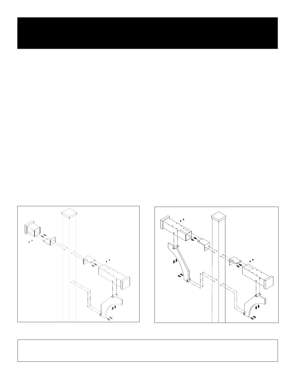
4870 Assembly
When you install a curbside or rural mailbox, make sure that it is easily
accessible to the mail carrier. By regulation it should be 41” to 45” from the
ground or street surface up to the inside floor of the mailbox. The door should
be set 6” to 8” from the front face of the curb or the road edge. However,
check with your postmaster to ensure that the mailbox is installed according to
local regulations.
4872 – 2 Sided for 2 Mailboxes
4874 – 2 Sided for 4 Mailboxes
First check to see that all the parts and fasteners in the carton have been
located and identified according to the illustration below. Also refer to the
illustration below to position the parts correctly. The 4874 has the same parts
as the 4872, except the two (2) arms are longer.
1. Attach the small right-angle bracket to the post with the long leg on top with
two (2) 5/16” x 1” long hex washer-head bolts.
2. Attach the long square-tube arm to the small right angle bracket with two
(2) 1/4”-20 x 1/2” long flat-head socket screws.
3. Attach the large decorative arch to the post and the long square-tube arm
with four (4) 5/16” x 1” long hex washer-head bolts.
4. Repeat steps 1 through 3 above for the second arm on the other side of the
post. This completes the assembly.
General Note: Use the four (4) hex-head bolts provided to install the mailbox
to the deluxe post. The nylon spacers install between the bottom of the
Salsbury 4850 mailbox and the top of the deluxe post arm.
4872 and 4874 Assembly


