Page is loading ...

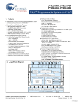
MPX-2515 User’s Guide Rev 0101
Taiwan Commate Computer Inc.
1
MPX-2515 User’s Guide
MPX-2515 CAN 2.0B USB card features USB 2.0 full speed to CAN 2.0B bus
interface in Mini-PCIe form factor. This MPX-2515 User's Guide describes how to
use MPX-2515 card.

Commell MPX-2515 User’s Guide Rev 0101
Taiwan Commate Computer Inc.
2
Contents
1 Technical Guide.......................................................................................................... 4
1.1 Introduction......................................................................................................... 4
1.1.1 Features....................................................................................................... 4
1.1.2 Supported Operating Systems..................................................................... 5
1.2 MPX-2515 Block Diagram................................................................................. 5
1.3 CY8C24794 Programmable System-on-Chip..................................................... 6
1.4 MCP2515 Stand-Alone CAN Controller With SPI Interface............................. 7
1.5 MCP2551 High-Speed CAN Transceiver......................................................... 11
1.6 MPX-2515 ISO OSI Model.............................................................................. 11
1.6.1 Introduction............................................................................................... 11
1.6.2 ISO11898-1 Physical Signaling................................................................ 13
1.7 MPX-2515 Card vs. ISO-11898-2.................................................................... 14
1.7.1 ISO-11898-2 Overview............................................................................. 14
1.7.2 Bus Levels................................................................................................. 15
1.7.3 Comparison............................................................................................... 16
1.8 MPX-2515 I/O Interfaces ................................................................................. 17
1.8.1 Mini Card Golden Finger.......................................................................... 18
1.8.2 CN_USB Connector.................................................................................. 19
1.8.3 Jumper for Line Termination.................................................................... 20
1.8.4 CN_CAN Connector................................................................................. 21
1.8.5 CN_ISSP Connector................................................................................. 23
1.9 MPX-2515 Card Properties............................................................................... 23
1.9.1 USB Properties.......................................................................................... 23
1.9.2 LED Indicators.......................................................................................... 26
1.10 OAL-2515 Cable............................................................................................... 27
1.11 OALUSB-H4-1 Cable....................................................................................... 28
1.12 OALUSB-H4 Cable.......................................................................................... 28
1.13 How to Connect ................................................................................................ 29
1.13.1 Connect to USB Host via Mini-PCIe Slot ................................................ 29
1.13.2 Connect to USB Host via Cable................................................................ 29
1.13.3 Connect to CAN Bus ................................................................................ 31
2 Device Drivers.......................................................................................................... 33
2.1 Device Drivers for Windows............................................................................ 33
2.1.1 Windows 2000.......................................................................................... 34
2.1.2 Windows XP (32-bit) Device Driver........................................................ 35
2.1.3 Windows XP (64-bit) Device Driver........................................................ 35
2.1.4 Windows Vista (32-bit) and Windows 7 (32-bit) Device Driver ............. 35
2.1.5 Windows Vista (64-bit) and Windows 7 (64-bit) Device Driver ............. 36
2.2 How to Install Device Driver............................................................................ 36
3 Firmware Update ...................................................................................................... 37
3.1 Introduction....................................................................................................... 37
3.2 Enter Boot Loader............................................................................................. 37
3.3 Install Boot Loader Device Driver.................................................................... 39
3.4 Boot Loader Host Application.......................................................................... 40
3.5 In Case Failed ................................................................................................... 44

Commell MPX-2515 User’s Guide Rev 0101
Taiwan Commate Computer Inc.
3
4 Reference.................................................................................................................. 46

Commell MPX-2515 User’s Guide Rev 0101
Taiwan Commate Computer Inc.
4
1 Technical Guide
1.1 Introduction
The MPX-2515 CAN 2.0B USB card is a USB 2.0 compliant device, which
implements Controller Area Network (CAN) version 2.0B interface. This card is
made in Mini-PCIe form factor so that this module is able to insert into motherboards
that provide Mini-PCIe slot, like most Commell motherboards do. In addition, users
are able to connect this card to an USB Type A receptacle that most PC has by using
the OALUSB-H4-1 optional cable. MPX-2515 CAN 2.0B USB card provides the
following features.
1.1.1 Features
• USB 2.0 Full Speed compliant
• Controller Area Network (CAN) version 2.0B
• Implement ISO-11898 Standard Physical Layer
• Supports 1 Mb/s operation (recommend 125 Kbps)
• Default to 125 Kbps
• On board 120 Ohm line terminator (enabled/disabled by jumper)
• 0 to 8 byte length in the data field
• Standard and extended data and remote frames
• Two receive buffers with prioritized message storage
• Six 29-bit filters
• Two 29-bit masks
• Data byte filtering on the first two data bytes
• One-shot mode ensures message transmission is attempted only one time
• Typical 5 mA active current
• Typical 1 uA standby current (sleep mode)
• Externally-controlled slope for reduced RFI emissions
• Detection of ground fault (permanent Dominant) on TXD input
• Power-on Reset and voltage brown-out protection
• Protection against high-voltage transients
• Automatic thermal shutdown protection
• Up to 112 nodes can be connected
• High-noise immunity due to differential bus implementation
• IEC 61000-4-2 (ESD) ± 15kV (air/contact) protection
• IEC 61000-4-4 (EFT) 50A (5/50ns) protection
• Produced in Mini-PCIe card form factor (easily locked on motherboard)

Commell MPX-2515 User’s Guide Rev 0101
Taiwan Commate Computer Inc.
5
Figure 1 MPX-2515 CAN 2.0B USB Card
1.1.2 Supported Operating Systems
The following operating systems are supported by MPX-2515:
• Microsoft Windows XP 32-/64-bit versions
• Microsoft Windows Vista 32-/64-bit versions
• Microsoft Windows 7 32-/64-bit versions
No Microsoft Windows 64-bit versions digital signature included.
1.2 MPX-2515 Block Diagram
The MPX-2515 CAN 2.0B USB card is composed of a System on Chip, a stand-alone
CAN controller, and a high-speed CAN transceiver.
Cypress
CY8C24794
SoC
Microchip
MCP2515
CAN
Controller
Microchip
MCP2551
CAN
Transceiver
USB bus CAN bus

Commell MPX-2515 User’s Guide Rev 0101
Taiwan Commate Computer Inc.
6
Figure 2 MPX-2515 Block Diagram
The above figure shows the components diagram of the MPX-2515 CAN 2.0B USB
card. The Cypress CY24794 controller implemented a USB device that interacts with
a USB host to perform requests and return responses. A Microchip MCP2515 CAN
controller is connecting to CY24794 via SPI and other signals. Another Microchip
MCP2551 CAN Transceiver is interfacing to the CAN bus to send and receive CAN
messages.
1.3 CY8C24794 Programmable System-on-Chip
We uses Cypress CY8C24794 PSoC Programmable System-on-Chip as the general
purpose controller for MPX-2515 card. A firmware has implement for CY8C24794 to
support full speed USB, SPI master, timers, and others for MPX-2515 functionalities.
The full speed USB interface is used to communicate with a USB host to perform
request packets and return response packets. The SPI master interface however is
used to communicate to the MCP2515 CAN bus controller for CAN activities. Please
refer to the CY8C24x94 PSoC Programmable System-on-Chip Technical Reference
Manual for detail information.
The following figure shows the block diagram of CY8C24794.

Commell MPX-2515 User’s Guide Rev 0101
Taiwan Commate Computer Inc.
7
Figure 3 CY8C24794 Block Diagram
1.4 MCP2515 Stand-Alone CAN Controller With SPI Interface
Microchip Technology's MCP2515 is a stand-alone Controller Area Network (CAN)
controller that implements the CAN specification, version 2.0B. It is capable of

Commell MPX-2515 User’s Guide Rev 0101
Taiwan Commate Computer Inc.
8
transmitting and receiving both standard and extended data and remote frames. The
MCP2515 has two acceptance masks and six acceptance filters that are used to filter
out unwanted messages. Thereby reducing the host MCUs overhead. The MCP2515
interfaces with CY8C24794 microcontroller via an industry standard Serial Peripheral
Interface (SPI).
The following figure shows the block diagram of MCP2515
Figure 4 MCP2515 Block Diagram
The MCP2515 has three transmit and two receive buffers, two acceptance masks (one
for each receive buffer) and a total of six acceptance filters. The following figure
shows the MCP2515 buffers and protocol engine block diagram. Please refer to
MCP2515 data sheet for detail information.

Commell MPX-2515 User’s Guide Rev 0101
Taiwan Commate Computer Inc.
9
Figure 5 MCP2515 Buffers and Protocol Engine Blcok Diagram
The following table shows the MCP2515 Controller Register Map. Please refer to the
MCP2515 data sheet for detail information.

Commell MPX-2515 User’s Guide Rev 0101
Taiwan Commate Computer Inc.
10
Figure 6 MCP2515 Controller Register Map
The following table shows the MCP2515 Control Register Summary. Please refer to
the MCP2515 data sheet for detail information.
Figure 7 MCP2515 Control Register Summary

Commell MPX-2515 User’s Guide Rev 0101
Taiwan Commate Computer Inc.
11
1.5 MCP2551 High-Speed CAN Transceiver
The MCP2551 is a high-speed CAN, fault-tolerant device that serves as the interface
between a CAN protocol controller and the physical bus. The MCP2551 device
provides differential transmit and receive capability for the CAN protocol controller,
and is fully compatible with the ISO-11898 standard, including 24V requirements. It
will operate at speeds of up to 1 Mb/s.
The following figure shows the MCP2551 block diagram. Please refer to the
MCP2551 data sheet for detail information.
Figure 8 MCP2551 Block Diagram
1.6 MPX-2515 ISO OSI Model
1.6.1 Introduction
This section defines the MPX-2515 card in the ISO OSI reference model. The
following figure shows this model.

Commell MPX-2515 User’s Guide Rev 0101
Taiwan Commate Computer Inc.
12
Figure 9 MPX-2515 ISO/OSI Reference Model
The Controller Area Network (CAN) protocol defines the Data Link Layer and part
of the Physical Layer in the OSI model. Therefore, all the undefined layers can be
defined by the system designer, or can be implemented using existing non-proprietary
High Layer Protocols (HLPs) and physical layers.
Data Link Layer The Data Link Layer is defined by the CAN specification. This
Data Link Layer is divided into Logical Link Control (LLC) Layer and Medium
Access Control Layer (MAC). The Logical Link Control (LLC) manages the overload
control and notification, message filtering and recovery management functions. the
Medium Access Control (MAC) performs the data encapsulation/decapsulation, error
detection and control, bit stuffing/destuffing and the serialization and deserialization
functions.
Physical Layer The Physical Medium Attachment (PMA) and Medium Dependent
Interface (MDI) are the two sub-layers of the physical layer which are not defined by
CAN. However, the Physical Signaling (PS) sub-layer of the physical layer is defined
by the CAN specification. The system designer can choose any driver/receiver and
transport medium as long as the PS requirements are met.
The International Standards Organization (ISO) has defined a standard which
incorporates the CAN specification as well as the physical layer. The standard, ISO-
11898, was originally created for high-speed in-vehicle communication using CAN.
ISO-11898 specifies the physical layer to ensure compatibility between CAN
transceivers.

Commell MPX-2515 User’s Guide Rev 0101
Taiwan Commate Computer Inc.
13
1.6.2 ISO11898-1 Physical Signaling
The bit encoding/decoding and synchronization shall meet the requirements defined
in ISO-11898-1 and it is recommended to follow the definitions as given in the
Recommended bit timing settings table. The according bus length estimations are
therefore shown in the table follows it.
Table 1 Recommended bit timing settings
The following table shows the according bus length estimations.

Commell MPX-2515 User’s Guide Rev 0101
Taiwan Commate Computer Inc.
14
Table 2 Estimated bus lengths
1.7 MPX-2515 Card vs. ISO-11898-2
1.7.1 ISO-11898-2 Overview
ISO-11898-2 is the international standard for high-speed CAN communications in
road vehicles. ISO-11898-2 specifies the PMA and MDA sub-layers of the ISO/OSI
Physical Layer.
The following figure shows a representation of a common CAN node/bus as
described by ISO-11898.

Commell MPX-2515 User’s Guide Rev 0101
Taiwan Commate Computer Inc.
15
Figure 10 CAN Node on Bus
1.7.2 Bus Levels
CAN specifies two logical states: recessive and dominant. ISO-11898 defines a
differential voltage to represent recessive and dominant states (or bits), as shown in
the following figure.

Commell MPX-2515 User’s Guide Rev 0101
Taiwan Commate Computer Inc.
16
Figure 11 CAN Differential Bus
Recessive State
In the recessive state (i.e., logic '1' on the MCP2551 TXD input), the differential
voltage on CANH and CANL is less than the minimum threshold (< 0.5V receiver
input or < 1.5V transmitter output).
Dominant State
In the dominant state (i.e., logic '0' on the MCP2551 TXD input), the differential
voltage on CANH and CANL is greater than the minimum threshold. A dominant bit
overdrives a recessive bit on the bus to achieve nondestructive bitwise arbitration.
1.7.3 Comparison
The ISO-11898-2 specification requires that a compliant or compatible transceiver
must meet a number of electrical specifications. The following table shows the major

Commell MPX-2515 User’s Guide Rev 0101
Taiwan Commate Computer Inc.
17
ISO-11898-2 electrical requirements vs. Microchip MCP2551 specification (and of
course MPX-2515 card).
Table 3 MPX-2515 (MCP2551) vs. ISO-11898-2
1.8 MPX-2515 I/O Interfaces
This section defines all input/output ports for MPX-2515 CAN 2.0B USB card. It
includes ports for connection and jumper for control.

Commell MPX-2515 User’s Guide Rev 0101
Taiwan Commate Computer Inc.
18
Figure 12 I/O Ports and Jumper
• Mini card golden finger - The USB signals of this industrial standard mini-
PCIe interface are used to connect to a USB host.
• CN_USB connector - The connector for connecting to a USB host by cable.
Please refer to its corresponding section for detail information.
• J1 - The Line Termination jumper.
• CN_CAN connector - The connector for connecting to the CAN bus.
• CN_ISSP connector - The connector for firmware uploading.
1.8.1 Mini Card Golden Finger
The MPX-2515 CAN 2.0B USB card implements only the USB D+ and USB D-,
ground, and 3.3V voltage supply of the mini card golden finger. Users can use this
mini card golden finger to connect to a USB host of the motherboard.
The following figure shows the location of golden finger of MPX-2515 card.
Figure 13 MPX-2515 Golden Finger

Commell MPX-2515 User’s Guide Rev 0101
Taiwan Commate Computer Inc.
19
The following figure shows the I/O pins definitions of MPX-2515 CAN 2.0B USB
card.
Figure 14 Golden Finger Pins Definitions
1.8.2 CN_USB Connector
This connector is provided to as an alternate to connect the MPX-2515 CAN 2.0B
USB card to a USB host. Users can connect OALUSB-H4-1 cable from this
connector to a USB Type A receptacle to connect to a USB host.
The following figures shows/defines the pins definitions.

Commell MPX-2515 User’s Guide Rev 0101
Taiwan Commate Computer Inc.
20
Figure 15 MPX-2515 OALUSB
Connector
Figure 16 CN_USB Pins Definitions
Please refer to the OALUSB-H4-1 section for the cable information.
1.8.3 Jumper for Line Termination
Users apply this line termination jumper to enable 120 Ohm line termination if the
MPX-2515 CAN 2.0B USB card is connecting to a CAN bus at the end side. Users
need to apply this 120 Ohm line terminator in order to increase the signaling quality
on the bus.
/