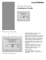
White Rodgers 8A04-1 Installation guide

Type
Installation guide

This manual is also suitable for

White Rodgers 8A04-1 SPDT Fan Relays are designed to provide a 24-volt control circuit for operating line voltage fan motors or other loads. They feature SPDT switch action for use with either single or two-speed motors, and can be mounted using mounting tabs or a 1/2-inch conduit hub. With a coil current of 0.28A at 24VAC, 60Hz, these relays are suitable for a wide range of applications. They also have a maximum load rating of 16 amps at 120VAC and 8 amps at 240VAC for normally open contacts, and 9.8 amps at 120VAC and 6.9 amps at 240VAC for normally closed contacts.

White Rodgers 8A04-1 SPDT Fan Relays are designed to provide a 24-volt control circuit for operating line voltage fan motors or other loads. They feature SPDT switch action for use with either single or two-speed motors, and can be mounted using mounting tabs or a 1/2-inch conduit hub. With a coil current of 0.28A at 24VAC, 60Hz, these relays are suitable for a wide range of applications. They also have a maximum load rating of 16 amps at 120VAC and 8 amps at 240VAC for normally open contacts, and 9.8 amps at 120VAC and 6.9 amps at 240VAC for normally closed contacts.

Printed in U.S.A.
WIRING
All wiring should be done in accordance with local and national electrical codes and ordinances.
Fig. 2 Using Type 8A04-1 with Single Speed Motor
Fig. 1 Using Type 8A04-1 with Two-Speed Motor
N.C.
TO 24 VOLT
CONTROL CIRCUIT
RELAY
COIL
BLUE
BROWN
PLENUM FAN SWITCH
OR OTHER SWITCHING DEVICE
TWO-SPEED
MOTOR
HOT
LINE
N
N.O.
N.C.
TO 24 VOLT
CONTROL CIRCUIT
RELAY
COIL
BLUE
BROWN
SINGLE-SPEED
MOTOR
HOT
LINE
N
LINE VOLTAGE
LOW VOLTAGE
WIRING
PLENUM FAN SWITCH
OR OTHER SWITCHING DEVICE
TYPE 8A04-1 FAN RELAY
BLACK
TYPE 8A04A-1 FAN RELAY
BLACK
HI
COM
LO
RED
BLUE
BLUE
N.O.
RED
PART NO. 37-5493A
Replaces 37-9234
9514
WHITE-RODGERS DIVISION
EMERSON ELECTRIC CO.
9797 REAVIS RD., ST. LOUIS, MO. 63123
(314) 577-1300, Fax (314) 577-1517
9999 HWY. 48, MARKHAM, ONT. L3P 3J3
(905) 475-4653, FAX (905) 475-4625
SPECIFICATIONS
ELECTRICAL DATA
Switch Action: Single-Pole, Double-Throw
Norm. Open (N.O.): Black - Red
Norm. Closed (N.C.): Black - Brown
Coil Current: 0.28A. @ 24V.A.C., 60Hz
Mounting: By means of mounting tabs or 1/2" conduit hub.
Replaces: Honeywell R8225; General R4
Contacts: Silver cadmium oxide
Contact Rating:
AMPS.
120VAC 240VAC
N.O. N.C. N.O. N.C.
FULL LOAD 16 9.8 8 6.9
LOCKED ROTOR 96 58.8 48 41.4
INSTALLATION INSTRUCTIONS
TYPE 8A04-1
FAN RELAY
24V Coil, SPDT Switch Action
WHITE-RODGERS
Operator: Save these instructions for future use!
FAILURE TO READ AND FOLLOW ALL INSTRUCTIONS CAREFULLY BEFORE
INSTALLING OR OPERATING THIS CONTROL COULD CAUSE PERSONAL
INJURY AND/OR PROPERTY DAMAGE.
DESCRIPTION
The Type 8A04-1 Fan Relay is for use with low voltage thermo-
stat to provide a 24 volt control circuit for operating a line voltage
fan motor or other load.
The relay has SPDT switch action to permit use with either single
or two-speed motor.
Diagrams presented on back of this sheet show various systems
that provide the required 24 volt power supply for operating the
coil of the Fan Relay.
To prevent electrical shock and/or equipment dam-
age, disconnect electric power to system, at main fuse
or circuit breaker box, until installation is complete.
Do not use on circuits exceeding specified voltages.
Higher voltages will damage control and could cause
shock or fire hazard.
PRECAUTIONS
CAUTION
If in doubt about whether your wiring is millivolt, line, or low
votage, have it inspected by a qualified heating and air condi-
tioning contractor, electrician, or someone familiar with basic
electricity and wiring.
Do not exceed the specification ratings.
All wiring must conform to local and national electrical codes and
ordinances.
This control is a precision instrument, and should be handled
carefully. Rough handling or distorting components could cause
the control to malfunction.
WARNING
2 37-5493B
RHY
W
RCG
Fig. 5 For Oil-Fired installations using low voltage Oil Burner Control
WIRING CONT.
Fig. 3 For installations where heating and cooling systems are powered by same transformer
RHY
W
G RC
Fig. 4 For installations where heating systems are powered by a separate transformer
RHY WG RC
THERMOSTAT
SWITCH
FAN
RELAY
COOLING
RELAY
HEATING
SYSTEM
FAN
RELAY
COOLING
RELAY
HEATING
SYSTEM
FAN
RELAY
COOLING
RELAY
24VAC
120VAC
DO NOT USE JUMPER WIRE ON TWO TRANSFORMER SYSTEM
COOLING
TRANSFORMER
TYPE 8A04-1
FAN RELAY
TO T1-T2 TERMINALS
ON OIL BURNER
CONTROL TYPE 668
COOLING
TRANSFORMER
TYPE 8A04-1
FAN RELAY
TYPE 8A04-1
FAN RELAY
HEATING
TRANSFORMER
TRANSFORMER
ADJUSTABLE
HEATING
ANTICIPATOR
SYSTEM
SWITCH
BIMETAL
HEAT
COOL
FAN
SWITCH
COOL
HEAT
HEAT
COOL
OFF
Internal Wiring
Field Wiring
The diagrams given below show the use of White-Rodgers
Heating-Cooling Thermostat Combinations on various systems
that provide the required 24 volt power supply for operating the
coil (blue leads) of the Type 8A04-1 Fan Relay.
All wiring should be done in accordance with local and national electrical codes and ordinances.
THERMOSTAT
SUBBASE
SYSTEM
SYSTEM
SYSTEM
24VAC
120VAC
24VAC
120VAC
SYSTEM
SWITCH
AUTO ON
OFF
24VAC
120VAC
FIELD-INSTALLED
JUMPER
FIXED
COOLING
ANTICIPATOR
2 37-5493B
RHY
W
RCG
Fig. 5 Pour les installations à mazout dont le brûleur est doté d'une commande à basse tension
CÂBLAGE SUITE
RHY
W
G RC
RHY WG RC
COMMUTATEUR DE
THERMOSTAT
24V C.A.
120V C.A.
NE PAS UTILISER DE CAVALIER AVEC UN SYSTÈME À DEUX TRANSFORMATEURS
TRANSFORMATEUR
DE CLIMATISATION
TRANSFORMATEUR
DE CHAUFFAGE
TRANSFORMATEUR
BILAME
CLIM.
CLIM.
CHAUF.
CHAUF.
CLIM.
ARRÊT
Câblage interne
Câblage effectué
sur place
THERMOSTAT
SOCLE
SYSTÈME
SYSTÈME
SYSTÈME
24V C.A.
120V C.A.
24V C.A.
120V C.A.
COMMUTATEUR
DE SYSTÈME
ARRÊT
24V C.A.
120V C.A.
CAVALIER INSTALLÉ
SUR PLACE
Fig. 4 Pour les installations dont les systèmes de chauffage et de climatisation sont alimentés par des
transformateurs distincts
Fig. 3 Pour les installations dont les systèmes de chauffage et de climatisation sont alimentés par le
même transformateur
Les schémas ci-dessous illustrent comment utiliser des
combinaisons de thermostats de chauffage et climatisation
White-Rodgers sur divers systèmes qui assurent l'alimentation
de 24 volts requise pour actionner la bobine (fils bleus) du relais
de ventilateur 8A04-1.
Tout le câblage doit être conforme aux codes et règlements locaux et nationaux qui régissent les installations électriques.
CHAUF.
ANTICIPATEUR
RÉGLABLE DE
CHAUFFAGE
ANTICIPATEUR
FIXE DE
CLIMATISATION
COMMUTATEUR
DE SYSTÈME
COMMUTATEUR
DE RELAIS
RELAIS DE
VENTILATEUR DE
TYPE 8A04-1
RELAIS DE
CLIMATISATION
RELAIS DE
VENTILATEUR
RELAIS DE
VENTILATEUR DE
TYPE 8A04-1
RELAIS DE
CLIMATISATION
RELAIS DE
VENTILATEUR
TRANSFORMATEUR
DE CLIMATISATION
VERS LES BORNES T1-T2 DE LA
COMMANDE DE BRÛLEUR À
MAZOUT DE TYPE 668
NE PAS UTILISER DE CAVALIER AVEC UN SYSTÈME À DEUX TRANSFORMATEURS
AUTO MARCHE
SYSTÈME DE
CHAUFFAGE
SYSTÈME DE
CHAUFFAGE
RELAIS DE
VENTILATEUR DE
TYPE 8A04-1
RELAIS DE
CLIMATISATION
RELAIS DE
VENTILATEUR
  • Page 1 1
  • Page 2 2
  • Page 3 3
  • Page 4 4

White Rodgers 8A04-1 Installation guide

Type
Installation guide
This manual is also suitable for

White Rodgers 8A04-1 SPDT Fan Relays are designed to provide a 24-volt control circuit for operating line voltage fan motors or other loads. They feature SPDT switch action for use with either single or two-speed motors, and can be mounted using mounting tabs or a 1/2-inch conduit hub. With a coil current of 0.28A at 24VAC, 60Hz, these relays are suitable for a wide range of applications. They also have a maximum load rating of 16 amps at 120VAC and 8 amps at 240VAC for normally open contacts, and 9.8 amps at 120VAC and 6.9 amps at 240VAC for normally closed contacts.

Ask a question and I''ll find the answer in the document

Finding information in a document is now easier with AI

in other languages