Page is loading ...

X-XX UL
INSTALLATION INSTRUCTIONS
®U.S. Registered Trademark
Copyright © 1999 Honeywell Inc. • All Rights Reserved
69-1293-1
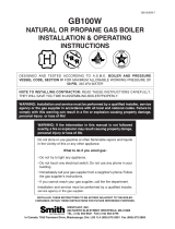
RA889A
Switching Relay
APPLICATION
The RA889A Switching Relay provides intermediate
switching of line- and low-voltage devices from a line- or
low-voltage controller and is typically applied in hydronic
heating systems.
SPECIFICATIONS
Electrical Ratings:
Voltage: 120 Vac, 60 Hz.
Thermostat Heat Anticipator Setting: 0.12A.
Transformer Ratings:
Primary: 120 Vac, 60 Hz.
Secondary: 24 Vac, 12 VA maximum; 9 VA available for
external loads. Secondary is protected by replaceable
1A automotive fuse.
Contact Ratings:
15 AFL, 30 ALR; maximum connected load 2000 VA.
Switching Action:
Spdt, plus extra low voltage Spst.
Electrical Connections:
No. 8 captivated wire clamp screw terminals.
Dimensions:
See Fig. 1.
Cross Reference:
The RA889A replaces many Honeywell models. See
Table 1 for additional cross reference information.
Replacement Parts:
Replacement Fuse: Use a 1A automotive fuse.
4
(114)
1
2
1
(48)
7
8
3
8
(10)
3
8
(10)
5
32
1 (29)
1
4
4 (108)
1
2
3 (89)
5
(133)
1
4
3
32
(2) DIAMETER
1
2
(13) DIAMETER
KEYHOLE TYPE
MOUNTING HOLE
7
8
(22) DIAMETER
7
32
(6) DIAMETER MOUNTING HOLE
1
(48)
7
8
25
32
(20)
KNOCKOUT FOR
1/2 (13) CONDUIT (3)
3
8
1 (35)
M3823A
2
(75)
15
16
Fig. 1. RA889A dimensions in in. (mm).

69-1293—1
2
RA889A SWITCHING RELAY
INSTALLATION
When Installing this Product . . .
1. Read these instructions carefully. Failure to follow
them could damage the product or cause a hazard-
ous condition.
2. Check the ratings given in the instructions and on
the product to make sure the product is suitable for
your application.
3. Installer must be a trained, experienced service
technician.
4. After installation is complete, check out product
operation as provided in these instructions.
5. Follow local codes for installation and application.
WARNING
Electrocution Hazard.
Power supply can cause severe injury,
or death.
Transformer core not bonded.
Disconnect power supply before wiring.
MOUNTING
In replacement applications, mount the new relay in the
same location as the old relay. For new installations,
locate the relay vertically on a solid wall or partition as
close as possible to the device to be controlled. Select a
location that is easily accessible for installation and
service.
NOTE: To reduce the possible transformer hum and
relay noise that is sometimes amplified by
mounting surfaces such as sheetmetal,
plasterboard, and similar materials, place
rubber or felt washers between the case and
the mounting surface.
1. Position the relay and mark the mounting holes. See
Fig. 1.
2. Start a screw in the upper right corner for the
keyhole type mounting hole. Screw it down within
about 1/8 in. (3 mm) of the surface.
3. Hang the relay on the screw, position the case, and
start the bottom screw.
4. Tighten both screws.
Table 1. RA889A Replacement Cross Reference.
Connections
Manu-
facturer Model
Input Line
Voltage Power Relay
Low Voltage
Relay Thermostat Comments
Honeywell RA889A L1 L2 COM N.O. N.C. X1 X2 W(T) R(T) C —
Honeywell RA89A
b
12 3 4 ———TT——
Honeywell R182A
b
12 78—BRSee Fig. 8
thermostat
connections.
Jumper L1 to COM and
between X1 and R(T) in
RA889A.
Honeywell R182B 1 2 8 6 7 B R Requires jumper
between X1 and R(T)
Honeywell R182C
a
12 8 6 7 B R
Honeywell R482B 1 2 8 6 7 — — Jumper R(T)
to W(T).
Line voltage switched
inputs go to L1 and L2.
Honeywell R482C
a
12 8 6 7 — —
See Fig. 7B.
Honeywell R482J
a
12 687—— Line voltage inputs
go to L1 and L2. See
Fig. 7B.
Honeywell R882A
b
—— 8 7 ———W—B
—
Honeywell R882B — — 8 6 7 — — W — B
Honeywell R882C
a
—— 8 6 7 — — W — B
Honeywell R882J
a
—— 6 8 7 — — 1 — 2
a
RA889A has one set of COM/N.O. relay contacts. Use R8845U if two sets are required.
b
RA889A has lower out
p
ut load ratin
g
. Check load re
q
uirements.

69-1293—1
3
RA889A SWITCHING RELAY
L1
HOTL2
R(T) W(T)
C
L2 L1
1
1
LOW VOLTAGE (CLASS 2)
2-WIRE THERMOSTAT
POWER SUPPLY. PROVIDE OVERLOAD PROTECTION
AND DISCONNECT MEANS AS REQUIRED.
X2X1
RELAY
LED
LOW-VOLTAGE
POWERPILE®
G
N.O.COM
TO
POWER
N.C.
LOAD 1
TO
POWER
1
M14295
AUTOMOTIVE
FUSE
Fig. 2. RA889A internal schematic
and typical hookup.
WIRING
CAUTION
Electrical Shock or Personal Injury Hazard.
Power supply can shock.
Use only NEC Class 1 wire for all line voltage
wiring connections. Class 1 wires must be rated for
at least 167°F (75°C).
All wiring must comply with all applicable electrical codes,
ordinances, and regulations. Follow all instructions
furnished with the controlled equipment.
IMPORTANT
The switching relay terminals are approved only
for use with copper wires.
When two or more line-voltage load devices are to be
controlled in parallel, the total current must not exceed the
rating for the relay load. Never connect load terminals to a
load that uses more current than the amount listed in the
electrical ratings on the relay. See Table 2 for wiring length
specifications. See the schematic and typical hookups in
Fig. 2 through 7.
GL2L1 T T
C1 C2
B2 B1
F
F
T
T
L1
(HOT)
L2
PUMP PUMP PUMP
T87F T87F T87F
RA889A
RELAY
RA889A RA889A
C554
R8184G
BURNER
AND
IGNITION
ORANGE
WHITE
BLACK
POWER SUPPLY. PROVIDE DISCONNECT MEANS AND OVERLOAD PROTECTION AS REQUIRED.
CONTROL CASE MUST BE CONNECTED TO EARTH GROUND. USE GROUNDING SCREW PROVIDED.
B1 IS 1/4 IN. TAB TERMINAL.
1
2
L7148A/L8148A
2
1
M14301
3
3
X2X1N.O.
COM
L2L1
W(T)R(T)
X2X1N.O.
COM
L2L1
W(T)R(T)
X2X1N.O.
COM
L2L1
W(T)R(T)
Fig. 3. RA889A hookup for L7148A/L8148A in an oil-fired, tankless hot water, zoned, pump system.
Table 2. Wire Lengths.
Wire
Size
Total Wire Length
Wire Length of Run
to Thermostat
(AWG)
Ft M Ft M
22 120 38.0 60 18.0
20 200 61.0 100 30.5
18 300 91.5 150 45.5
16 500 152.5 250 76.0
14 800 244.0 400 122.0

69-1293—1
4
RA889A SWITCHING RELAY
Fig. 5. R8888 zone expansion using additional RA889A Switching Relays.
C2 C1
H1 H2
L2 L1 L1 ZC
R W
R C A B C
R W R W R W
C2 C1 C2 C1 C2 C1
ZONE 1
ZONE 2
ZONE 3
ZONE 4
CIRCULATOR
PUMP 1
CIRCULATOR
PUMP 2
CIRCULATOR
PUMP 3
CIRCULATOR
PUMP 4
CIRCULATOR
PUMP 5
ZONE 1
THERMOSTAT
ZONE 5
THERMOSTAT
ZONE 2
THERMOSTAT
ZONE 3
THERMOSTAT
ZONE 4
THERMOSTAT
L1
L2
X2
X1
N.O.
CONTROL CASE MUST BE CONNECTED TO EARTH GROUND.
USE GROUNDING SCREW PROVIDED.
1
1
20 VA
M13321
R8888
1
G
RA889A
R(T)
W(T)
TO APPROPRIATE
CONNECTIONS
AS REQUIRED
BY THE SYSTEM.
H1-H2 TYPICALLY
CONNECTED TO
T-T OF BURNER
CONTROL SYSTEM.
ZC
H1
H2
2
2
USE COPPER CONDUCTORS ONLY. FOR ALL CLASS 1
CONNECTIONS, USE WIRE RATED FOR AT LEAST 167°F (75°C).
G
L2 L1
3
4
4
POWER SUPPLY. PROVIDE DISCONNECT MEANS AND OVERLOAD
PROTECTION AS REQUIRED.
CONNECT L1-ZC JUMPER, IF REQUIRED.
L1
(HOT)
L2
3
COM
Fig. 4. RA889A hookup for L7148F/L8148E in a gas-fired, 24V, zoned, pump system.
R(T) W(T)R(T) W(T)
R(T)
W(T)
L1
L2
COM
N.O.
X1 X2
GL2L1 T T
C1 C2
B2 B1
L1
(HOT)
L2
PUMP PUMP PUMP
T87F T87F T87F
RA889A RELAY
RA889A RA889A
POWER SUPPLY. PROVIDE DISCONNECT MEANS AND
OVERLOAD PROTECTION AS REQUIRED.
CONTROL CASE MUST BE CONNECTED TO EARTH GROUND.
USE GROUNDING SCREW PROVIDED.
B1 IS 1/4 IN. TAB TERMINAL.
1
2
3
3
L7148F/L8148E
2
1
M13314
LOW VOLTAGE
GAS VALVE
(eg, VR8300)
TR
TH
THTR
L1
L2
COM
N.O.
X1 X2
L1
L2
COM
N.O.
X1 X2

69-1293—1
5
RA889A SWITCHING RELAY
Fig. 6. RA889A thermostat connections.
W(T)
C
R(T)
X1
B
X2
W(T)
RA889A
RA889A
THREE-WIRE
LOW VOLTAGE
(SERIES 10)
THERMOSTAT
TWO-WIRE
LOW VOLTAGE
(SERIES 80)
THERMOSTAT
1
1
MAKES CONTACT ONLY ON TEMPERATURE FALL.
M13316
R(T)
C
X1
X2
W(T)
R(T)
Fig. 7. RA889A control options.
L1
L2
COM
R(T)
N.C.
N.O.
C
W(T)
RA889A
M13317
A. FOR 24V THERMOSTAT CONTROL
R
C
W
THERMOSTAT
B. FOR LINE VOLTAGE CONTROL
C. FOR EXTERNAL SEPARATE LOW VOLTAGE POWER SOURCE
OPTIONAL
L1, (HOT)
NEUTRAL
LINE VOLTAGE
CONTROLLED
OUTPUTS
X2
X1
LOW VOLTAGE
CONTROLLED OUTPUT
L1
L2
COM
N.C.
N.O.
C
RA889A
JUMPER
LINE VOLTAGE
CONTROL
NEUTRAL
X2
X1
L1
L2
COM
N.C.
N.O.
C
RA889A
NEUTRAL
X2
X1
24V CONTROLLER
INPUT SUPPLY
R(T)
W(T)
R(T)
W(T)
1 REQUIRED FOR OUTPUT LED OPERATION.
2 FOR SERIES 10 OR OTHER HARDWIRED ELECTRONIC 3-WIRE
THERMOSTATS.
3 WARNING! ELECTROCUTION HAZARD. POWER SUPPLY CAN
CAUSE SEVERE INJURY OR DEATH. DISCONNECT POWER BEFORE
WIRING OR SERVICING L1. POWERED RELAYS MUST BE WIRED AS
DRY CONTACTS.
1
2
3
CHECKOUT
1. Keep the cover on the relay during normal operation
and remove only for service and checkout.
2. Relay contacts require no cleaning; they are
arranged to close with a wiping action and are self-
cleaning. The contacts may turn black after being in
service for some time; this discoloration does not
prevent proper operation.
3. After installation is complete, operate system
through at least one cycle from the controller to
make certain the relay controls the equipment as
intended.
TROUBLESHOOTING
Test Button
— This connection is the same as a call for heat connec-
tion between the R(T) and W(T) terminals.
Relay LED
— This LED lights whenever there is 120 Vac (L1) on
the N.O. terminal (when COM/N.O. relay contacts
are closed).

69-1293—1
6
RA889A SWITCHING RELAY
Honeywell Limited-Honeywell Limitée
35 Dynamic Drive
Scarborough, Ontario M1V 4Z9
69-1293—1 G.R. Rev. 7-99
Automation and Control Solutions
Honeywell International Inc.
1985 Douglas Drive North
Golden Valley, MN 55422
customer.honeywell.com
/