
113319-2-EA(-)
Copyright 1996 Kohler Co.
REVIVAL
ACCESSORIES
BEFORE YOU BEGIN
A. HOW TO USE THESE INSTRUCTIONS
Please read these instructions carefully to familiarize
yourself with the required tools, materials, and installation
sequences. Follow the sections that pertain to your
particular installation. This will help you avoid costly
mistakes. In addition to proper installation, read all
operating and safety instructions.
All information in this manual is based upon the latest
product information available at the time of publication.
Kohler Co. reserves the right to make changes in product
characteristics, packaging, or availability at any time
without notice.
B. PRODUCT NOTES
Give some thought to the exact location desired for
these products. While it is possible to mount these
products on any surface, it is best to find a wall stud
to secure them to.
Use a level to ensure that the centerline for the wall
bracket(s) is vertical. Use a level to ensure that the
post centerlines are level.
NOTE: For the K-16145 Mirror, do not drill the
mounting holes for the second support plate until the
actual product is measured.
DANGER: Risk of personal injury. These products
are not designed or intended for use as a grab bar or
support bar. Do not install any of these products in any
area where they are likely to be used inadvertently as
a grab bar or support bar. For additional information,
ASTM F446 defines critical support areas.
C. ORDERING INFORMATION
Towel ring K-16140. . . . . . . . . . . . . . . . . . . . . . . . . . .
Toilet tissue holder K-16141. . . . . . . . . . . . . . . . . . .
Soap dish K-16142. . . . . . . . . . . . . . . . . . . . . . . . . . .
24” glass shelf K-16143. . . . . . . . . . . . . . . . . . . . . . .
Mirror K-16145. . . . . . . . . . . . . . . . . . . . . . . . . . . . . .
Robe hook K-16146. . . . . . . . . . . . . . . . . . . . . . . . . .
Towel bar, 30” K-16147. . . . . . . . . . . . . . . . . . . . . . .
Towel bar, 18” K-16148. . . . . . . . . . . . . . . . . . . . . . .
Tumbler holder K-16149. . . . . . . . . . . . . . . . . . . . . .
Towel bar, 24” K-16150. . . . . . . . . . . . . . . . . . . . . . .
Towel shelf K-16155. . . . . . . . . . . . . . . . . . . . . . . . . .
D. REQUIRED TOOLS AND MATERIALS
Tape measure
Assortment of screwdrivers
Level (24” or longer)
Pencil
Electric drill with 5/16” bit
1/8” hex head wrench
3/32” hex head wrench (K-16143)
Adjustable wrench
Clean strap wrench
Hammer
NOTE: Site preparation and wall finishing may require
additional tools and materials.

2 Kohler Co., Kohler, WI
113319-2-EA(-)
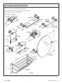
ROUGHING-IN INFORMATION
Fig. #1
K-16140
K-16141
K-16142
K-16143
K-16146
K-16147
K-16148
K-16150
K-16149
4-7/8”
3-1/4”
5-7/16”
5-7/16”
3-1/4”
3-13/16”
5-1/6”
K-16147: 30”
K-16148:18”
K-16150: 24”
3-1/4”
3-1/4”
24-3/8”
8-1/8”
3-1/4”
4-3/4”
5-5/8”
3-1/4”
4-3/4”
25-1/2”
9-3/4”
10-1/2”
K-16155
Determine the exact mounting location desired.
With the exception of the K-16156 grab bar, do not locate
these products in critical support areas.
Allow adequate clearance.
K-16145
3-3/4”
28-1/2”

3Kohler Co., Kohler, WI
113319-2-EA(-)
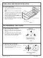
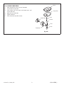
TOWEL SHELF AND GRAB BAR INSTALLATION
A. K-16155 TOWEL SHELF
1. Loosen the setscrew at the bottom of each shelf support.
Then remove the brackets from inside the shelf
supports.
NOTE: Use care to avoid scratching the product
finish.
2. Secure the three shelf sections to the shelf supports
(large section on top; small section on bottom) using the
hex screws provided. Tighten securely.
3. Refer to the roughing-in information on Page 2. Then
mount the brackets to the wall in the desired location. Be
sure to mount the brackets plumb.
4. Set the shelf assembly over the brackets, and securely
tighten the setscrews at the bottom of each shelf
support. Do not overtighten.
Fig. #2
Setscrew
Shelf Assembly
Hex Screw
Bracket
Shelf
Support
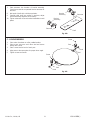
SITE PREPARATION – WALL PLATES
A. MARK CENTER POINT LOCATIONS
NOTE: For K-16145 Mirror, do not drill mounting holes
for second support plate until actual product is
measured.
1. Mark the center points of the accessory to be installed.
2. For multiple-post accessories, provide the required
distance between center points. See Fig. #1 . Use a
level to ensure that all center points are level.
Fig. #3
Level
Center Point
Single-Post Accessories
Center-to-Center Points
Multiple-Post Accessory
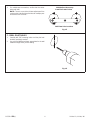
B. MARK PILOT HOLE LOCATIONS
1. Mark the pilot hole locations vertically 9/16” above and
below the center point or center points.
2. Vertically line up holes on the wall plate. Make sure the
larger hole is on the bottom.
Fig. #4
1-1/8” D.
9/16” R.
Holes
Wall Bracket
Wall Plate Hole Locations

4 Kohler Co., Kohler, WI
113319-2-EA(-)
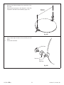
3. For multiple-post accessories, confirm that the center
points are level.
NOTE: There is no provision for later adjustment if the
center points and resulting pilot holes for multiple-post
accessories are not level.
Fig. #5
Multiple-Post Accessory
Center-to-Center Points
Wall Plate Hole Locations
C. DRILL PILOT HOLES
1. Carefully drill 5/16” mounting holes at all the pilot hole
locations previously marked.
2. Use a bit and drilling technique appropriate for the wall
material through which you are drilling.
Fig. #6

5Kohler Co., Kohler, WI
113319-2-EA(-)
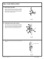
WALL PLATE INSTALLATION
A. INSERT WALL ANCHORS
1. Press and hold the legs of a wall anchor (provided)
together, and insert the wall anchor legs into the hole.
Insert all wall anchors into the pre-drilled mounting holes.
2. With a hammer, carefully tap each wall anchor until all
are flush with the finished surface.
Fig. #7
B. SPREAD ANCHORS AS NECESSARY
1. If the wall anchor was inserted into a space between the
studs, it will be necessary to spread the wall anchor legs.
2. Insert a narrow rod, such as a finishing nail, into the wall
anchor hole to spread the legs behind the wall surface.
3. Repeat for all wall anchors inserted between studs.
Fig. #8
Nail
4. Ensure that the wall anchors are flush with the finished
surface.
Fig. #9
Finished Surface

6 Kohler Co., Kohler, WI
113319-2-EA(-)
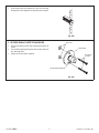
5. If the wall anchors are inserted into a hole in a wall stud,
the legs will remain together and provide proper support.
Fig. #10
C. SECURE WALL PLATE TO ANCHORS
1. Orient a wall plate with the large mounting hole down as
shown.
2. Secure with supplied panhead screws into the centers of
the mounting holes.
3. Repeat for all wall plates supplied.
Fig. #11
Anchors
Wall Plate
Panhead
Screws
Large Mounting Hole

7Kohler Co., Kohler, WI
113319-2-EA(-)
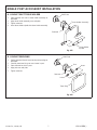
SINGLE POST ACCESSORY INSTALLATION
A. K-16141 TOILET TISSUE HOLDER
1. Start setscrew into hole in tissue holder assembly as
illustrated.
2. Align tissue holder assembly over wall plate.
3. Tighten setscrew.
4. Insert tissue holder spindle into tissue holder assembly.
Fig. #12
Wall Plate
Tissue Holder Assembly
Setscrew
Tissue Holder
Spindle
B. K-16140 TOWEL RING
1. Set the large end of each insert into the post openings as
illustrated.
2. Carefully ease towel ring over over inserts in post.
3. Start setscrew into hole in post.
4. Align post over wall plate.
5. Tighten setscrew.
Fig. #13
Wall Plate
Post
Towel Ring
Insert
Insert
Setscrew

8 Kohler Co., Kohler, WI
113319-2-EA(-)
C. K-16146 ROBE HOOK
1. Place robe hook through hole in post and secure with
knob as illustrated.
2. Start setscrew into hole in post.
3. Align post over wall plate.
4. Tighten setscrew.
Fig. #14
Post
Robe Hook
Wall Plate
Setscrew
Knob
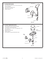
D. K-16149 TUMBLER HOLDER
1. Start setscrew into hole in post as illustrated.
2. Thread rod into holder subassembly.
3. Place sleeve over rod, place rod through post, and
secure with knob.
4. Align post over wall plate.
5. Tighten setscrew.
6. Place tumbler into holder subassembly recess.
Fig. #15
Tumbler
Holder
Subassembly
Rod
Sleeve
Post
Setscrew
Wall
Plate
Knob

9Kohler Co., Kohler, WI
113319-2-EA(-)
E. K-16142 SOAP DISH
1. Start setscrew into hole in post as illustrated.
2. Thread rod into soap dish.
3. Place sleeve over rod, place rod through post, and
secure with knob.
4. Align post over wall plate.
5. Tighten setscrew.
6. Place insert into soap dish recess.
Fig. #16
Insert
Soap Dish
Rod
Sleeve
Knob
Post
Wall Plate
Setscrew

10 Kohler Co., Kohler, WI
113319-2-EA(-)
MULTIPLE-POST ACCESSORY INSTALLATION
A. K-16147, K-16148 TOWEL BARS
1. Place towel bar through one post and secure with a
knob.
2. Place a ferrule, small end first, over open end of towel
bar.
3. Place sleeve over open end of towel bar.
4. Place a ferrule, large end first, over open end of towel
bar.
5. Align second post over towel bar assembly and secure
loosely with knob.
Fig. #17
Post
Knob
Ferrule
Towel Bar
Sleeve
Post
Knob
Ferrule
6. Start a setscrew into each post hole as illustrated.
7. Align towel bar assembly posts post over wall plates.
8. Tighten setscrews.
9. Tighten knobs on towel bar assembly.
Fig. #18
Wall Plate
Setscrew
Towel Bar
Assembly
Setscrew
Wall Plate
B. K-16143 GLASS SHELF
1. Start setscrew into hole in post as illustrated.
2. Thread a stud into a bracket.
3. Place stud through post, and secure with knob.
4. Align post over wall plate.
5. Loosely secure setscrew.
6. Repeat for second post assembly.
Fig. #19
Wall Plate
Post
Setscrew
Knob
Stud
Bracket

11Kohler Co., Kohler, WI
113319-2-EA(-)
7. Start setscrews into brackets of bracket assembly.
Check that screws do not protrude into the recesses for
the shelf.
8. Wet ends of shelf with a mild soap solution.
9. Carefully slide shelf into position in brackets; adjust
bracket assembly alignment as necessary.
10. Tighten setscrews to secure bracket assemblies to wall
plates.
Fig. #20
Bracket
Assembly
Setscrew
Shelf
Setscrew
Bracket
Assembly
C. K-16145 MIRROR
1. Place mirror face down on a flat, padded surface.
2. Place a post over over each mirror stud and secure
loosely with a knob.
3. Start a screw into the back of each post.
4. Align posts to the same plane for proper mirror angle.
5. Tighten screws and knobs.
Fig. #21
Screw
Post
Knob
Stud
Post
Stud
Knob
Screw

12 Kohler Co., Kohler, WI
113319-2-EA(-)
6. Measure the distance between the center-lines of the
two posts.
7. Install second wall plate to this dimension. (See Site
Preparation and Wall Plate Installation, pages 3-6.)
Fig. #22
Measure
Distance
8. Have a helper align and place mirror assembly over wall
plates.
9. Secure with setscrews.
Fig. #23
Wall Plate
Setscrew
Mirror
Assembly
-
 1
1
-
 2
2
-
 3
3
-
 4
4
-
 5
5
-
 6
6
-
 7
7
-
 8
8
-
 9
9
-
 10
10
-
 11
11
-
 12
12


Ask a question and I''ll find the answer in the document
Finding information in a document is now easier with AI
Related papers
-
Kohler K-16295-CP Installation guide
-
Kohler K-3810-96 Installation guide
-
-
Kohler K-16142 User manual
-
-
-
Kohler K-12153-CP Installation guide
-
-
Kohler 16142-BV Installation guide
-
Kohler K-485-BN Installation guide
Other documents
-
Hans Grohe 41534XX1 User manual
-
Minka Group 1430-84 User manual
-
 UniCaddy 01162500 Operating instructions
-
 MODONA 4H03-A Installation guide
-
 MODONA 3H03-A Installation guide
-
Design House 587196 Operating instructions
-
 USE 1774.01 Installation guide
-
Speakman VS-153-ADA-BN Installation guide
-
Unbranded SN808C-34 User manual
-
 USE 1777.01 Operating instructions


