Page is loading ...

SMD Servo Tester
Item no. 19 01 51
Intended Use
The product serves functional inspection of model car servos. Commissioning requires soldering on of a
connection cable for a battery and a servo connection cable (battery and cable not in the delivery).
This product complies with the statutory national and European requirements. All company names and product
names are trademarks of their respective owners. All rights reserved.
Scope of Delivery
• Servo Tester
• Operating instructions
Safety Information
The guarantee/warranty will expire if damage is incurred resulting from non-compliance
with the operating instructions! We do not assume any liability for consequential damage!
We do not assume any liability for property damage and personal injury caused by
improper use or non-compliance with the safety instructions! In such cases the warranty/
guarantee is voided.
• Unauthorized conversion and/or modification of the product are not permissible for safety and approval
reasons (CE).
• This product is not a toy and not suitable for children.
• The servo tester must not become damp or wet.
• Disconnect the battery from the servo tester if you are not using it.
• Always use a battery or rechargeable battery pack to operate the servo tester. Never use a wall mains
adapter.
• Soldering work must be performed with a matching soldering rod (small soldering tip, max. 50 W heating
output) and the corresponding soldering knowledge.
If you do not have any matching soldering rod and/or not enough soldering knowledge, contact an
experienced model construction colleague or a workshop. Non-observance poses danger of injury from
burns and/or damage to the PCB (loss of warranty/guarantee).
• Do not leave packaging material unattended. It may become a dangerous toy for children.
Connection
a) Solder on Cable for Battery Connection
Solder a suitable cable for the battery connection to the servo tester PCB (not included in the delivery). Ideally,
the connection cable has an integrated on/off switch.
Observe the polarity. The red cable of the battery must be soldered to the plus pole („+“), the black cable to
the minus pole („-“) of the PCB. In case of non-observance, the servo tester and connected servo/speed
controller will be destroyed; loss of warranty/guarantee!
b) Connect Servo or Speed Controller
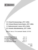
Solder a suitable 3-pin cable with the corresponding servo socket (not included) to the solder pads shown in
the figure. Observe correct assignment at the servo tester. The usual colours of the servo cables are:
Yellow/white/orange cable = control signal
This cable must be soldered to the connection „P“ (= positive control impulse) of the PCB of the servo tester.
Red cable = operating voltage
This cable must be soldered to the „+“ connection of the PCB.
Brown/black cable = minus/GND
This cable must be soldered to the „-“ connection of the PCB.
Note:
• The figure shows the connection points „P“ and „N“. The servo tester provides a positive
control impulse at the connection point „P“. At the connection point „N“, this impulse is
negative. Most remote controls and servos work with a positive control impulse, however.
• Many speed controllers have a BEC (a BEC is a receiver current supply integrated into the
speed controller). In this case, no dedicated power supply (e.g. a battery) must be used for
operation of the servo tester!
The servo tester is supplied directly via the speed controller BEC by the drive battery. If a
separate power supply is to be used for the servo tester instead of the BEC integrated into the
speed controller, the middle, red, wire of the three-pole receiver plug of the speed controller
must be interrupted. If this is not observed, the speed controller and/or servo tester will be
destroyed! Loss of guarantee/warranty!
• Alternatively, you may design the power supply of the servo tester with a plug. In this case, you
can unplug the battery of the servo tester to test a speed controller with BEC.
• The potentiometer displayed at the left of the figure is soldered correctly ex works.
Commissioning
Connect the three-pin plug of the servo or speed controller to the servo tester. Connect a battery to the servo
tester (observe notes on the BEC in the previous chapter!). The servo now moves according to the rotating
movements of the potentiometer of the servo tester.
Practical advice:
• We recommend that you install the servo tester into a suitable housing to avoid, e.g., short circuits. Ideally,
the housing should be chosen at a size that provides enough space for a matching battery to operate the
servo tester.
• Use matching cables with plug connectors for connecting the battery or servo (not in the delivery). Ideally,
cables with the same plug-in system as your remote control should be used.
• The manufacturers of remote control systems use some different impulse lengths that are measured in
milliseconds („ms“) for the neutral position and the end deflections of servos. Common values for this are
1.5 ms for servo centre, 1 ms for full deflection left and 2 ms for full deflection right.
• The servo tester covers the most common impulse length range of different manufacturers and can even
generate smaller (0.75 ms) or larger (2.2 ms) impulse lengths. Therefore, we recommend that you calibrate
your servo tester for your remote control. Test the neutral position as well as the end deflections of the servos
(without trimming or electronic path adjustments) of your remote control and apply these values to a suitable
scale (see the example in figure 1 as well). This makes it possible to check or adjust the servo settings and
deflections with the servo tester without taking into operation your remote control.
• Ensure that the rudder linkages are running easily when testing servos and do not block at full deflection.
This warranty maximum control deflections with high return accuracy.
Disposal
Dispose of the product according to the applicable statutory provisions at the end of its service life.
Technical Data
Operating voltage .............................. 4 to 6 V/DC
Impulse width ..................................... 0.75 to 2.2 ms
Dimensions (L x W) ........................... 24 x 15 mm
+
-
4,8 V
Servo
P
N
+
-
0
L
R
These operating instructions are a publication by Conrad Electronic SE, Klaus-Conrad-Str. 1,
D-92240 Hirschau (www.conrad.com).
All rights including translation reserved. Reproduction by any method, e.g. photocopy, microfilming,
or the capture in electronic data processing systems require the prior written approval by the editor.
Reprinting, also in part, is prohibited.
These operating instructions represent the technical status at the time of printing. Changes in
technology and equipment reserved.
© Copyright 2012 by Conrad Electronic SE.
Operating instructions
Version 07/12
/