Page is loading ...

Bedienungsanleitung
4-Kanal-Fernsteueranlage 2,4 GHz
Seite 2 - 34
Operating Instructions
4-channel-remote control 2.4 GHz
Page 35 - 67
Notice d’emploi
Télécommande à 4 canaux 2,4 GHz
Page 68 - 100
Gebruiksaanwijzing
4-kanaals-afstandsbediening 2,4 GHz
Pagina 101 - 133

35
Table of Contents
Page
1. Introduction ........................................................................................................................................................ 37
2. Explanation of Symbols .....................................................................................................................................37
3. Intended Use .....................................................................................................................................................38
4. Product Description ...........................................................................................................................................38
5. Scope of Delivery ...............................................................................................................................................38
6. Safety Notes ......................................................................................................................................................39
a) General ........................................................................................................................................................39
b) Operation .....................................................................................................................................................40
7. Notes on Batteries and Rechargeable Batteries ................................................................................................41
8. Charging Rechargeable Batteries ......................................................................................................................42
9. Operating Elements of the Transmitter .............................................................................................................. 43
10. Setting up the Transmitter ..................................................................................................................................44
a) Aligning the Transmitter Aerial .....................................................................................................................44
b) Inserting the Batteries/Rechargeable Batteries ........................................................................................... 44
c) Charging the Rechargeable Batteries for Transmitter .................................................................................45
d) Switching on the Transmitter .......................................................................................................................45
e) Setting the Control Levers ........................................................................................................................... 46
11. Setting up the Receiver .....................................................................................................................................47
a) Connecting the Receiver .............................................................................................................................47
b) Mounting the Receiver .................................................................................................................................48
12. Installing the Servos ..........................................................................................................................................49
13. Setting the Digital Trim .......................................................................................................................................50
14. Checking the Servo Directions of Travel ............................................................................................................51
15. Switching the Servo Directions of Travel ...........................................................................................................55
16. Changing the Control Lever Allocation ..............................................................................................................56
17. Servo path limiter (Dual Rate) ...........................................................................................................................57
18. Activating the Integrated Mixers ........................................................................................................................59
a) Delta Mixer ..................................................................................................................................................59
b) V-Tail Mixer .................................................................................................................................................. 60
19. Binding Function ................................................................................................................................................ 62
20. Fail-Safe Setting ................................................................................................................................................63

36
Page
21. Range Test .........................................................................................................................................................64
22. Maintenance and Care ......................................................................................................................................64
23. Disposal ............................................................................................................................................................. 65
a) General ........................................................................................................................................................65
b) Batteries and Rechargeable Batteries ......................................................................................................... 65
24. Declaration of Conformity (DOC) ....................................................................................................................... 65
25. Troubleshooting .................................................................................................................................................66
26. Technical Data ...................................................................................................................................................67
a) Transmitter...................................................................................................................................................67
b) Receiver ......................................................................................................................................................67

37
1. Introduction
Dear Customer,
thank you for purchasing this product.
This product complies with the statutory national and European requirements.
To maintain this status and to ensure safe operation, you as the user must observe these operating instructions!
These operating instructions are part of this product. They contain important notes on commissioning and
handling. Also consider this if you pass on the product to any third party. Therefore, retain these operating
instructions for reference!
If there are any technical questions, please contact:
International: www.conrad.com/contact
United Kingdom: www.conrad-electronic.co.uk/contact
2. Explanation of Symbols
The exclamation mark in a triangle indicates important notes in these operating instructions that must be
observed strictly.
The arrow symbol indicates that special advice and notes on operation are provided.

38
3. Intended Use
Theremotecontrolissolelydesignedforprivateuseintheeldofmodelconstructionandtheoperatingtimesassoci-
ated with it. This system is not suitable for industrial use, such as controlling machines or equipment.
Any use other than that described above can damage the product and involves additional risks such as short circuit,
re,electricshock,etc.Theproductmustnotbetechnicallymodiedorrebuilt!Thesafetyinformationmustbeob-
served at all times!
Observe all safety information in these operating instructions. They contain important information on han-
dling of the product.
You are solely responsible for the safe operation of your remote control and your model!
4. Product Description
The 4-channel-remote control system is a radio control system that is mainly ideal for controlling model planes.
However, this remote control can also be used to control model vehicles or model ships. The four proportional control
channels can be used to remote-control the different control functions independently of each other. The ergonomic
casingtscomfortablyintoyourhandandallowsforeasyandsafeoperationofthemodelandthetransmitter.
For operation, 4 AA/mignon batteries (e.g. Conrad item no. 652507, pack of 4, order 1x) or rechargeable batteries
forthetransmitterarerequired.WherenodriveorightcontrollerwithBECisused,youalsoneed4typeAA/Mignon
batteries for the receiver (e.g. Conrad item no. 652507, order once) or rechargeable batteries and a suitable battery
holder. Alternatively, a 4-cell or a 5-cell receiver battery pack with switch cable can be used as well.
5. Scope of Delivery
• Remote control transmitter
• Remote control receiver
• Double-sided adhesive type for receiver installation
• Operating instructions
Current operating instructions
Download the current operating instructions via the link www.conrad.com/downloads or scan the
QR code displayed. Observe the instructions on the website.

39
6. Safety Notes
In case of damage caused by non-compliance with these operating instructions, the warranty/
guarantee will expire. We do not assume any liability for consequential damage!
We do not assume any liability for property damage or personal injury caused by improper use or
non-compliance with the safety instructions! In such cases the warranty/guarantee is voided.
Normal wear and tear in operation and damage due to accidents (like the receiver aerial being torn off, the
receiver casing broken etc.) are excluded from the warranty.
Dear customer, these safety instructions are not only for the protection of the product but also for your own
safety and that of other people. Therefore, read this chapter very carefully before taking the product into
operation!
a) General
Caution, important note!
Operating the model may cause damage to property and/or individuals. Therefore, make sure that you are
sufcientlyinsuredwhenusingamodel,e.g.bytakingoutprivateliabilityinsurance.
If you already have private liability insurance, verify whether or not operation of the model is covered by
your insurance before commissioning your model.
Observe: In some countries you are required to have insurance for all model aircraft!
• Theunauthorizedconversionand/ormodicationoftheproductisinadmissiblebecauseofsafetyand
approval reasons.
• This product is not a toy and not suitable for children under 14 years of age.
• The product must not get damp or wet.
• Taking out private liability insurance is recommended. If you already have one, get some information on
whether or not the operation of a radio-operated model is covered by your insurance.
• Do not connect the drive motor to electric models before the receiver system has been installed com-
pletely. This ensures that the drive motor does not start unintentionally.
• Do not leave packaging material unattended. It may become a dangerous toy for children.
• Please check the functional safety of your model and of the remote control system each time before you
use the model. Watch out for any visible damage such as defective plug connections or damaged cables.
All movable parts on the model have to be running smoothly. However, there must be no tolerance or
"play" in the bearing.
• Should questions arise that are not answered with the help of this operating manual, contact us (contact
information, see chapter 1) or another expert.

40
b) Operation
• Ifyoudonotyethavesufcientknowledgeonhowtodealwithremote-controlledmodels,pleasecontact
an experienced model sportsman or a model construction club.
• Whenputtingthedeviceintooperation,alwaysturnonthetransmitterrst.Thenswitchonthereceiver
in the model. Otherwise, the model might show unpredictable responses! Angle the transmitter aerial to
the side of the model in order to obtain the best transmission signal emission. Avoid directing the tip of
the aerial directly towards your eyes.
• Before operating the model, check whether the stationary model reacts as expected to the commands
of the remote control.
• When you operate the model, always make sure that no parts of your body, other people or objects come
within the dangerous range of the motors or any other rotating drive parts.
• Improper operation can cause serious damage to people and property! Always make sure that the model
is in your line of sight and do not operate it at night.
• Onlyoperateyourmodelifyourabilitytorespondisunrestricted.Fatigueortheinuenceofalcoholor
medication can lead to wrong responses.
• Operate your model in an area where you do nor endanger any persons, animals or objects. Only oper-
ateitonprivatesitesorinplaceswhicharespecicallydesignatedforthispurpose.
• In case of a fault stop operating your model straight away and remove the cause of malfunction before
you continue to use the model.
• Do not operate your RC system during thunderstorms, beneath high-voltage power lines or in the prox-
imity of radio masts.
• Never switch off the remote control (transmitter) while the model is in use. To switch off the model, always
switchoffthemotorrst,thenswitchoffthereceiver.Onlythenmaytheremotecontrolbeswitchedoff.
• Protect the remote control from dampness and heavy dirt.
• Do not expose the remote control to direct sunlight or excessive heat for a long period of time.
• If the batteries (or rechargeable batteries) in the remote control are low, the range decreases. If the
rechargeable battery in the receiver is low, the model will not respond correctly to the remote control.
If this is the case, stop remote-controlled operation immediately. Replace the batteries with new ones or
recharge the rechargeable batteries.
• Do not take any risks when operating the product! Your own safety and that of your environment depends
completely on your responsible use of the model.

41
7. Notes on Batteries and Rechargeable Batteries
• Keep batteries/rechargeable batteries out of the reach of children.
• Do not leave any batteries/rechargeable batteries lying around openly. There is a risk of batteries being
swallowed by children or pets. If swallowed, consult a doctor immediately!
• Batteries/rechargeablebatteriesmustneverbeshort-circuited,disassembledorthrownintore.There
is a danger of explosion!
• Leaking or damaged batteries/rechargeable batteries can cause chemical burns to skin on contact;
therefore, use suitable protective gloves.
• Donotrechargenormalbatteries.Thereisariskofreandexplosion!Chargeonlyrechargeablebatter-
ies intended for this; use suitable chargers.
• Always observe correct polarity (positive/+ and negative/-) when inserting the batteries/rechargeable
batteries.
• If the device is not used for an extended period of time (e.g. storage), remove the inserted batteries/
rechargeable batteries from the remote control and the car to avoid damage from leaking batteries/
rechargeable batteries.
• Recharge the rechargeable batteries about every 3 months. Otherwise, so-called deep discharge may
result, rendering the rechargeable batteries useless.
• Always replace the entire set of batteries or rechargeable batteries. Never mix fully charged batteries/
rechargeable batteries with partially discharged ones. Always use batteries or rechargeable batteries of
the same type and manufacturer.
• Never mix batteries and rechargeable batteries! Either use batteries or rechargeable batteries for the
remote control.
• The remote control (transmitter) may be operated with rechargeable batteries instead of batteries.
• However, the lower voltage (batteries = 1.5 V, rechargeable batteries = 1.2 V) and the lower capacity of
rechargeable batteries do lead to a decrease of the operating time. Normally this does not matter, since
the operating time of the remote control exceeds that of the model.
• When using batteries in the remote control, we recommend the use of high-quality alkaline batteries.
• When using rechargeable batteries, the range may decrease.

42
8. Charging Rechargeable Batteries
The rechargeable mignon batteries required for the RC system are, in general, uncharged on delivery and must be
charged.
Observe:
Before a rechargeable battery reaches maximum capacity, several complete discharge and charge cycles
are necessary.
Always discharge the rechargeable battery at regular intervals, since charging a +half-full" NiMH recharge-
able battery several times can cause a so-called lazy battery effect. This means that the rechargeable
battery loses capacity. It no longer provides all of its stored energy, and the operating time of the model and
the remote control is reduced.
If you use several rechargeable batteries, purchasing a high-quality charger may be worthwhile. Such a
charger usually has a quick-charging feature.

43
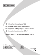
9. Operating Elements of the Transmitter
1 Transmitter aerial
2 Carrying handle
3 D/R-switch for channel 1
4 Trim button for elevator function (in mode II*)
5 Control stick for elevator and aileron function
(in mode II*)
6 Trim button for aileron function
7 Charging socket
8 On/off switch
9 D/R setting controller for channel 1
10 D/R setting controller for channel 2
11 Binding button
12 Trim button for rudder function
13 Control stick for rudder and motor function
(in mode II*)
14 Trim button for motor function (in mode II*)
15 D/R-switch for channel 2
16 LED for function display
17 LED for voltage display
Figure 1
* The remote control system is delivered ex works in the control lever assignment mode II. On demand, it is possible
to swap the control lever functions for the elevator and the motor function and to operate the transmitter in mode I.
For further information, refer to the chapter 16.

44
10. Setting up the Transmitter
Important note:
Inthefurthercourseoftheseinstructions,guresinthetextalwaysrefertotheadjacentgureorthegures
withinthesection.Referencestootherguresareindicatedwiththecorrespondinggurenumber.
a) Aligning the Transmitter Aerial
Anglethetransmitter'saerial(seegure1,item1)totheside,sothattheaerialisata90°angletotheimagined
connection line remote control/model.
Ifthereceiveraerialinthemodelisalignedhorizontally,alsoadjustthetransmitteraerialhorizontally(seegure1).If
the receiver aerial in the model is aligned vertically, also adjust the transmitter aerial vertically. The tip of the transmit-
ter aerial then points towards the head of the remote control system operator during model operation. This is how you
will achieve best signal transmission to the model.
Transmission to the model is lowest when you point the transmitter aerial tip at the model. This must be avoided in
any case.
Also do not touch the transmitter aerial in model operation. This reduces the transmission output and therefore also
the transmitter range.
b) Inserting the Batteries/Rechargeable Batteries
For the power supply of the transmitter you will need 4 batteries (e.g. Conrad item no. 652507, pack of 4,
order 1x) or rechargeable batteries mignon size (AA). For ecological and also for economical reasons it is recommend-
ed to use rechargeable batteries, since they can be recharged in the transmitter via a built-in charging socket (see
gure1,item7).
Proceed as follows to insert the batteries or rechargeable batteries:
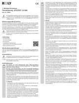
The battery compartment lid (1) is located on the back of the
transmitter. Press the corrugated area (2) and push off the
lid downwards.
Ensure that the polarity is correct when inserting the 4 bat-
teries/rechargeable batteries. A corresponding note (3) is
located on the bottom of the battery compartment.
Only the four middle battery compartments are equipped.
The two shafts to the right and left remain empty.
Then slide the lid of the battery compartment back on from
the bottom until the locking mechanism engages.
Figure 2

45
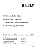
c) Charging the Rechargeable Batteries for Transmitter
When rechargeable batteries are inserted, you can connect
the charger cable to the charging socket (1) to charge the
rechargeable batteries in the transmitter. Always make sure
the polarity of the connecting plug is correct. The inner con-
tact of the charging socket must be connected to the plus
terminal (+) and the outer contact to the minus terminal (-)
of the charger.
The charging current should be about 1/10 of the capac-
ity of the inserted rechargeable batteries. For rechargeable
batteries with a capacity of 2000 mAh, this corresponds to a
charging current of approx. 200 mA and charging time takes
approx. 14 h.
Since a protective diode is integrated in the transmitter, no
chargerscanbeusedthatbrieyinterruptthechargingcur-
rent in order to measure the voltage of the rechargeable bat-
tery. In this case, remove the rechargeable batteries from
the transmitter for charging.
Attention!
Only connect the charger when you have inserted rechargeable batteries (1.2 V/cell) in the transmitter.
Never try to recharge batteries (1.5 V/cell) with a charger.
In order to avoid damage to the internal conductor paths and connections, please do not use any quick
chargers. The maximum charging current must not exceed 300 mA!
d) Switching on the Transmitter
When new batteries or freshly charged rechargeable bat-
teries have been inserted, switch on the transmitter with the
on/offswitch(seegure1,item8)fortestpurposes.Push
the operating button from the bottom to the top position.
First, the red LED for voltage supply will light up (also see
gure1,item17).Ashorttermlater,theremotecontrolemits
two signals and the green LED for the function display (also
seegure1,item16)startstolightup.
When the delta or V-tail mixer is activated, the
green LED of the function display will not be per-
manentlylit,butwillatataquickrhythm.
Ifthevoltagesupplydropstolessthan4.2V,thegreenLEDforundervoltage(alsoseegure1,item16)startsash-
ing quickly and the transmitter will emit short signal sounds at the same rhythm. In this case, stop operation of your
model as quickly as possible.
To continue operating the transmitter, recharge the batteries or insert new batteries.
Afteryouhaveveriedthecorrectfunctionofyourtransmitter,switchitoffagain.
Figure 3
Figure 4

46
e) Setting the Control Levers
You can adjust the length of the control levers, depending
on your steering habits.
To do so simply hold the bottom part of the grip (1) and turn
the upper part (2) up anti-clockwise.
You can now set the length of the control lever by turning the
bottom part of the grip.
Finally, tighten the upper part of the grip back up.
Figure 5

47
11. Setting up the Receiver
a) Connecting the Receiver
The receiver offers the possibility of connecting 4 servos
(receiver output 1, 2, 3, and 4) that are later assigned the
following control functions in the model:
CH1 = Aileron servo
CH2 = Elevator servo
CH3=Throttleservo/ightcontroller
CH4 = Rudder servo
Receiver output 5 is not used and a battery box (1) or a
receiver battery is connected to the receiver output B/6.
Attention!
When using servos with high power demand, we
recommend that you always use a receiver bat-
tery pack and not a battery box.
When using a ight controller with BEC, a re-
ceiver battery does not need to be connected.
The connections are intended for Futaba plugs protected
against polarity reversal and can also be used with JR plugs
if required.
When connecting servos and speed controllers, always make sure of correct polarity of the plug connec-
tors. The plug-in connection for the positive lead (yellow, white or orange, depending on the manufacturer)
must be connected to the inner (left) pin contact. The plug-in connection for the negative lead (black or
brown, depending on the manufacturer) must be connected to the outer (right) pin contact.
First, switch on the transmitter and then the receiver. If the binding function is working correctly, the red LED indicator
(seegure6,item3)inthereceiverrightnexttothesetupbutton(seegure6,item2)lightsupandthefourservos
react to the movements of the control levers. Verify correct receiver function and then switch the receiver off again.
If the receiver does not react and the LED in the receiver does not light up, perform binding (see
chapter 19).
Figure 6

48
b) Mounting the Receiver
Installation of the receiver depends on the model. For this reason, you should always follow the recommendations
of the model manufacturer regarding the installation. Regardless of the model, you should always try to install the
receiver so that it is protected from dust, dirt, moisture and vibration in the best possible way.
Keepenoughdistancefrommotorsandelectronicightorspeedcontrollers.Metalorcarbonpartshaveashielding
effect and thus may considerably impair reception. In this case, it is sensible to relocate the aerial outwards through
a bore in the fuselage.
Two-sided adhesive foam (servo tape) or rubber rings that hold the foam-wrapped receiver securely in place are
suitable for fastening the receiver.
Attention!
The receiver aerial (1) is the unshielded part of
the aerial line and has a length that is precisely
dimensioned.
For this reason, you must not roll up the aerial,
place it in a loop or cut it off. This would decrease
therangesignicantlyandthusposeaconsider-
able safety risk.
Figure 7

49
12. Installing the Servos
The installation of a servo (not included in the delivery) al-
ways depends on the particular model used. Detailed infor-
mation on this can be found in the construction documents
of the model.
Generally, however, try screwing in the servos (1) in a vi-
bration-dampened manner. This is why rubber bushings (2)
with metal sleeves (3) are usually included with the servos.
When servo arms or linkages are obstructed, the servos
cannot assume the required positions. This causes higher
power consumption and the model cannot be controlled
properly.
Always mount the servo lever (1) at a 90° angle to the link-
age rods (see sketch A).
The rudder or steering travel will not be equal on both sides
if the servo lever is mounted at an angle to the linkage rod
(sketch B) in spite of symmetrical rotting movement of the
servo lever.
Important!
The linkage rods or the rudder linkages must be
designed so that they do not mechanically limit
the possible rotating area of the servo lever early.
The servo may be damaged by this.
Figure 8
Figure 9

50
13. Setting the Digital Trim
The trim mostly serves to correct the slight inclination of the servo levers due to the interlock and the connected ir-
regular control movements. Additionally, there is the option to adjust the model in operation precisely, e.g. if it is not
yingstraightalthoughthecontrolleverisinthemiddleposition.
Then the linkage or rudder rods must be adjusted so that the trim has its original value (90°-range between servo lever
and rods) again and the model still runs straight.
The 4-channel-remote control has a digital trimming with which the four control channels can be individually set with
atrimmingbutton(alsoseegure1,items4,6,12and14).
The trimming buttons are assigned the following control functions:
Trimming button 4
= elevator servo at the receiver output 2
Trimming button 6
= aileron servo at the receiver output 1
Trimming button 12
= rudder servo at the receiver output 4
Trimming button 14
= throttle servo at the receiver output 3
Tocheckthesettingofthedigitaltrimming,rstswitchonthetransmitterandthenthereceiver.Ifatrimmingbutton
is moved to the side or up or down and held, the transmitter will emit brief signal sounds in a quick sequence and at
different tone heights. The servo of the respective control channel will change the position of the servo lever in small
steps. When the end of the trimming range is reached, a longer tone sounds and the signal sounds then go out. The
servo lever will no longer remove then.
Ifthetrimmingbuttonisthendeectedintheoppositedirectionandheld,thesignalsoundssoundagainandtheservo
lever turns back to the middle position step by step.
When the middle position of the trimming range is reached, the remote control will emit two slightly longer signal
sounds at the same height.
Now set the middle positioning of the trimming in all four channels and install the servo levers so that they are at a
90° angle to the rods. Since the servo levers and the servo axis are interlocked, very small inclinations of the servo
lever cannot always be avoided. In this case, the trimming of the respective channel must be adjusted slightly from the
middletoreturntothe90°angleoftheservolevertothelinkagerod(seegure8).
The set trim value is automatically saved in the remote control and is retained even after switching it off and
on.
When using the electrical model with an electronic motor controller, the trim for channel 3 also needs to be set to the
middle value.
Figure 10

51
14. Checking the Servo Directions of Travel
Connect the servos inserted in the model to the receiver. Pay attention to the assignment of the receiver outputs as
described above.
If your model has two aileron servos, there is the possibility of operating both servos with a V-cable at one
receiveroutput.Theservosthenmustbeinstalledonthewingsothatdifferentdeectiondirectionsresult
at the ailerons.
Caution, important!
To securely inspect the rudder function at an electrical model, the motor should be disconnected from the
speed controller or at least the propeller should be unscrewed. Secure the model against accidental rolling
away.
Now, take the transmitter into operation, then the receiver. If attached correctly, the servos at outputs 1, 2 and 4 should
reactintherightdirectiontothemovementsofthecontrolleversaccordingtothefollowingillustrations(seegures
11 to 14).
Important!
The linkage rods of the rudders must be adjusted so that the rudders are all aligned precisely centrally if
thecontrolleverandtheelectronictrimmingsareinthecentralpositions(seegure11).
Figure 11

52
Whentherightcontrolleverispulledtowardsthebody,theelevatormustdeectupwards.Whentherightcontrollever
ispushedforward,theelevatormustdeectdownwards(seegure12).
Figure 12
Whentherightcontrolleverisdeectedtotheright,therightaileronfromtherearmustdeectupwardsandtheleft
aileronmustdeectdownwards.Whentherightcontrolleverisdeectedtotheleft,therightaileronfromtherearmust
deectdownwardsandtheleftaileronmustdeectupwards(seegure13).
Figure 13

53
Whentheleftcontrolleverisdeectedtotheright,theruddermustdeecttotherightwhenviewedfrombehindwhile
lookingatthemodelfrombehind.Whentheleftcontrolleverisdeectedtotheleft,theruddermustdeecttotheleft
whenviewedfrombehind(seegure14).
Figure 14
When the left control lever is pulled towards the body, the rotating speed of the motor will reduce. The motor should be
switched off in the bottom position. When the left control lever is pushed to the front, the rotating speed of the motor
willincrease.Inthefrontposition,themotorshouldrunatmaximumoutput(seegure15).
Figure 15
The left control lever for motor control can be pushed forward and back without being moved back to the
middle position by spring force. It always remains in the position into which it was last moved.
/