Page is loading ...

2-Kanal-Fernsteueranlage „GT2“ 2.4GHz
2-Channel Remote Control System „GT2“ 2.4GHz
Radiocommande 2 canaux «GT2» 2.4GHz
2-kanaals afstandsbediening „GT2“ 2.4GHz
Best.-Nr. / Item no. / N° de commande / Bestelnr.: 20 76 00
Bedienungsanleitung Seite 2 - 20
Operating Instructions Page 21 - 39
Notice d’Emploi Page 40 - 58
Gebruiksaanwijzing Pagina 59 - 77
Version 08/12

21
Table of Contents
Page
1. Introduction ......................................................................................................................................................... 22
2. Intended Use ....................................................................................................................................................... 22
3. Product Description ............................................................................................................................................. 23
4. Scope of Delivery ................................................................................................................................................ 23
5. Explanation of Symbols ...................................................................................................................................... 23
6. Safety Information ............................................................................................................................................... 24
a) General Information ....................................................................................................................................... 24
b) Operation ........................................................................................................................................................ 25
7. Notes on Batteries and Rechargeable Batteries ................................................................................................ 26
8. Charging Rechargeable Batteries ...................................................................................................................... 26
9. Transmitter Controls ............................................................................................................................................ 27
10. Setting up the Transmitter................................................................................................................................... 28
a) Inserting the Batteries/Rechargeable Batteries ............................................................................................. 28
b) Charging the Rechargeable Batteries for the Transmitter ............................................................................. 28
c) Switching on the Transmitter .......................................................................................................................... 29
11. Setting up the Receiver....................................................................................................................................... 30
a) Connecting the Receiver ................................................................................................................................ 30
b) Installing the Receiver .................................................................................................................................... 31
12. Installing the Servos ............................................................................................................................................ 32
13. Verification of Steering and Drive Functions ...................................................................................................... 33
a) Verification of the Steering Function .............................................................................................................. 33
b) Verification of the Drive Function ................................................................................................................... 34
14. Binding Function ................................................................................................................................................. 35
15. Using the Transmitter as a Simulator ................................................................................................................. 35
16. Setting the Fail Safe Function ............................................................................................................................ 36
17. Maintenance and Care ....................................................................................................................................... 37
18. Disposal............................................................................................................................................................... 37
a) General Information ....................................................................................................................................... 37
b) Batteries and Rechargeable Batteries ........................................................................................................... 37
19. Troubleshooting .................................................................................................................................................. 38
20. Technical Data ..................................................................................................................................................... 39
a) Transmitter...................................................................................................................................................... 39
b) Receiver ......................................................................................................................................................... 39
21. Declaration of Conformity (DOC) ........................................................................................................................ 39

22
1. Introduction
Dear Customer,
Thank you for purchasing this product.
This product meets the requirements of current statutory, European and national guidelines.
To maintain this status and to ensure safe operation, you as the user must observe these operating instructions!
Observe all safety notes in these operating instructions. They contain important information
regarding the handling of the product.
You are solely responsible for the safe operation of your remote control and your model!
All company names and product names are trademarks of the respective owners. All rights reserved.
In case of any technical questions, contact or consult:
Tel. no.: +49 9604 / 40 88 80
Fax. no.: +49 9604 / 40 88 48
E-mail: [email protected]
Mon. to Thur. 8.00am to 4.30pm
Fri. 8.00am to 2.00pm
2. Intended Use
The 2-channel remote control system has been designed solely for private use in the model-making field and has
operating times appropriate to this use. This system is not suitable for industrial use, such as controlling machines or
equipment.
Any use apart from the use described above can damage the product and may lead to other risks, such as
short circuit, fire, electric shock, etc. Do not change or modify any technical aspects of the remote control
system. The safety notes must be observed at all times!
Observe all safety notes in these operating instructions. They contain important information regarding the
handling of the product.
You are solely responsible for the safe operation of your remote control and your model!

23
3. Product Description
The 2-channel remote control system is a radio control system that is ideal for controlling model vehicles or model
ships.
The driving and steering functions can be remote-controlled separately using the two proportional control channels.
The ergonomic housing fits comfortably into your hand and allows for easy and safe operation of the model and the
transmitter.
8 Mignon batteries (e.g. Conrad Item-No. 652507, 4-pack, please order 2 packs) or rechargeable batteries are required
to operate the transmitter. If no BEC speed controller is used, the transmitter requires 4 mignon batteries (e.g. Conrad
item no.: 652507, pack of 4, order 1 pack) or rechargeable batteries.
4. Scope of Delivery
• Transmitter
• Receiver
• Programming plug
• Operating instructions
5. Explanation of Symbols
The symbol with the exclamation mark points out particular dangers associated with handling, function or
operation.
The "arrow" symbol indicates special advice and operating information.

24
6. Safety Information
In case of damage caused by non-compliance with these safety instructions the warranty / guarantee
will become void. We do not assume any responsibility for consequential damage!
We do not assume any liability for damage to property or personal injury caused by improper use
or the failure to observe the safety instructions! In such cases the warranty/guarantee is void.
Normal wear and tear in operation and damage due to accidents (like the receiver aerial being torn off, the
receiver housing broken etc.) are excluded from the warranty.
Dear customer, these safety instructions are not only for the protection of the product but also for your own safety and
that of other people. Therefore, read this chapter very carefully before putting the product into operation!
a) General Information
Caution, important note!
Operating the model may cause damage to property and/or individuals.
Therefore, make sure that you are properly insured when using the model, e.g. by taking out private
liability insurance. If you already have private liability insurance, inquire about whether the operation of the
model is covered before operating it.
• The unauthorized conversion and/or modification of the product is prohibited for safety and approval reasons (CE).
• The product is not a toy and should be kept out of reach of children under 14 years of age.
• The product must not become damp or wet.
• Do not connect the drive motor to electric models before the receiver system has been installed completely. This
ensures that the drive motor does not start unintentionally.
• Do not leave packaging material unattended. It may become a dangerous toy for children.
• Please check the functional safety of your model and of the remote control system each time before you use the
model. Watch out for visible damage such as defective plug connections or damaged cables. All moving parts must
run smoothly, but should not have any play in their bearings.
• Should technical questions arise that are not answered in these operating instructions, please contact us (for contact
information, see Section 1) or ask another expert.
The operation and handling of RC models must be learned! If you have never controlled such a model, start especially
carefully to get used to how it responds to the remote commands. Do be patient!

25
b) Operation
• If you do not yet have sufficient knowledge on how to deal with remote-controlled models, please contact an
experienced model sportsman or a model construction club.
• When putting the device into operation, always turn on the transmitter first. Then switch on the receiver in the model.
Otherwise, the model might show unpredictable responses! Angle the transmitter aerial to the side of the model in
order to obtain optimal transmission signal emission. Avoid directing the tip of the aerial directly towards your eyes.
• Before operating the model, check whether the stationary model reacts as expected to the commands of the remote
control.
• When you operate the model, always make sure that no parts of your body, other people or objects come within the
dangerous range of the motors or any other rotating drive parts.
• Improper operation can cause serious damage to people and property! Always make sure that the model is in your
line of sight and do not operate it at night.
• Only operate your model if your ability to respond is unrestricted. Fatigue or the influence of alcohol or medication
can lead to wrong responses.
• Operate your model in an area where you do not endanger other people, animals or objects. Only operate it on
private sites or in places which are specifically designated for this purpose.
• In case of an error, stop operating your model immediately and remove the cause of malfunction before you continue
to use the model.
• Do not operate your RC system during thunderstorms, under high-voltage power lines or in the proximity of radio
masts.
• Never switch off the remote control (transmitter) while the model is in use. To switch off the model, always switch off
the motor first, then switch off the receiver. Only then may the remote control be switched off.
• Protect the remote control from dampness and heavy dirt.
• Do not expose the remote control to direct sunlight or excessive heat for an extended period of time.
• If the batteries (or rechargeable batteries) in the remote control are low the range decreases. If the rechargeable
battery in the receiver is low, the model will not respond correctly to the remote control.
If this is the case, stop driving immediately. Replace the batteries with new ones or recharge the rechargeable
batteries.
• Do not take any risks when operating the product! Your own safety and that of your environment is solely down to
you being responsible when dealing with the model.

26
7. Notes on Batteries and Rechargeable Batteries
• Keep batteries/rechargeable batteries out of the reach of children.
• Do not leave any batteries/rechargeable batteries lying around openly. There is a risk of batteries being swallowed
by children or pets. If swallowed, consult a doctor immediately!
• Batteries/rechargeable batteries must never be short-circuited, disassembled or thrown into fire. There is a danger
of explosion!
• Leaking or damaged batteries/rechargeable batteries can cause chemical burns to skin when touched without the
use of adequate protective gloves.
• Do not recharge normal batteries. There is a risk of fire and explosion! Only charge rechargeable batteries intended
for this purpose. Use suitable battery chargers.
• Please observe correct polarity (positive/+ and negative/-) when inserting the batteries/rechargeable batteries.
• If the device is not used for a longer period of time (e.g. storage), take out the inserted batteries/rechargeable
batteries inserted in the remote control and in the car to avoid damage from leaking batteries/rechargeable batteries.
Recharge the rechargeable batteries about every 3 months, because otherwise there may be a total discharge due
to self-discharge, which makes the rechargeable batteries useless.
• Always replace the entire set of batteries or rechargeable batteries. Never mix fully charged batteries/rechargeable
batteries with partially discharged ones. Always use batteries or rechargeable batteries of the same type and
manufacturer.
• Never mix batteries and rechargeable batteries! Either use batteries or rechargeable batteries for the remote control.
The remote control (transmitter) may be operated with rechargeable batteries instead of batteries.
However, the lower voltage (batteries=1.5 V, rechargeable batteries=1.2 V) and the lower capacity of
rechargeable batteries lead to a decrease of the operating time. Normally this does not matter, since the
operating time of the remote control exceeds that of the model.
If you use batteries in the remote control, we recommend the use of high-quality alkaline batteries.
8. Charging Rechargeable Batteries
The rechargeable mignon batteries required for the RC system are, in general, empty on delivery and must be charged.
Please note:
Before a rechargeable battery reaches maximum capacity, several complete discharge and charge cycles
are necessary.
Always discharge the rechargeable battery at regular intervals, since charging a "half-full" rechargeable
battery several times can cause a so-called memory effect. This means that the rechargeable battery
loses its capacity. It no longer provides all of its stored energy, and the operating time of the model and the
remote control is reduced.
If you use several rechargeable batteries, purchasing a high-quality charger may be worthwhile. Such a
charger usually has a quick-charging feature.

27
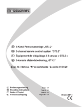
9. Transmitter Controls
Front:
1. Transmitter aerial
2. Steering wheel for the steering function
3. Operating lever for drive function
4. Transmitter base with integrated battery case
5. Operating panel cover
Operating panel (under the cover):
If you fold the operating panel cover upwards, you will gain
access to the other transmitter operating elements.
6. Reverse switch for the drive function
7. LED for under voltage display
8. Binding button
9. Dual-Rate control for steering
10. Function switch
11. Trimming control for the drive function
12. Trimming control for the steering function
13. LED for operating check
14. Reverse switch for the steering function
Rear:
15. PC link jack
16. Charging jack
Figure 1
Figure 3
Figure 2

28
10. Setting up the Transmitter
In the operating instructions, the numbers in the text always refer to the figure opposite or the figures within
the section. Cross-references to other figures will be indicated by the corresponding figure number.
a) Inserting the Batteries/Rechargeable Batteries
For the power supply of the transmitter you will need 8 alkaline batteries or rechargeable batteries mignon size (AA).
For ecological and economical reasons it is recommended to use rechargeable batteries, since they can be recharged
in the transmitter through the built-in charging socket.
To insert the batteries or rechargeable batteries, please proceed as follows:
The battery compartment lid (1) is located on the bottom of
the transmitter. Press on the corrugated area (2) and slide
open the cover by pushing it sideways.
Now insert the 8 batteries or rechargeable batteries into the
battery compartment. Always make sure the polarity of the
batteries is correct. The negative pole (housing) of the battery
or rechargeable battery must have contact with the spiral
spring.
A corresponding notice (3) is located on the bottom of the
battery compartment.
Please note that the 4 batteries/accumulators on the right
have to be slid underneath the peg (4) first before inserting
the other 4 batteries/accumulators.
Afterwards slide the lid of the battery compartment back on
and let the locking mechanism click into place.
b) Charging the Rechargeable Transmitter Batteries
When rechargeable batteries are inserted, you can connect
the charger cable to the charging socket (16) to charge the
rechargeable batteries in the transmitter.
Always make sure the polarity of the connecting plug is
correct. The inner contact of the charging socket must be
connected to the positive terminal (+) and the outer contact
to the negative terminal (-) of the charger.
The charging current should correspond to approximately
1/10 of the capacity value of the inserted rechargeable
batteries. For rechargeable batteries with a capacity of 2000
mAh this corresponds to a charging current of approx. 200
mA and charging time takes approx. 14 h.
Figure 4
Figure 5

29
Since a protective diode is integrated in the transmitter, no chargers can be used that briefly interrupt the charging
current in order to measure the voltage of the rechargeable battery. In this case, remove the rechargeable batteries
from the transmitter for charging.
In order to avoid damage to the internal conductor paths and connections, please do not use any quick chargers. The
maximum charging current must not exceed 500 mA!
Attention!
Connect the charger only if the rechargeable batteries (1.2V/cell) have been inserted in the transmitter.
Never try to recharge normal batteries (1.5V/cell) with a charger.
c) Switching on the Transmitter
When new batteries or freshly charged rechargeable
batteries have been inserted, switch on the transmitter with
the function switch (see figure 2, item 10) for test purposes.
For this, slide the operating switch from the right (OFF) to
the left (ON).
The red operating control LED (see figure 2, item 13) is lit
and indicates the on/off state of your transmitter. The green
under-voltage display LED (see figure 2, item 7) indicates
sufficient power supply of the transmitter.
If the supply voltage drops below 9 V, the green under-voltage LED starts flashing. In this case, you should
stop operating your model as quickly as possible. To continue operating the transmitter, recharge the
batteries or insert new batteries.
In order to avoid the memory effect of NiCd rechargeable batteries, you should connect the charger only
when the rechargeable batteries are completely discharged.
After you have verified the correct function of your transmitter, switch it off again.
Figure 6

30
11. Setting up the Receiver
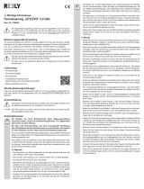
a) Receiver Connection
The receiver offers the possibility of connecting 3 servos
(receiver output CH1, CH2, CH3/BIND) and one
rechargeable receiver battery (VCC).
The connections are intended for Futaba plugs protected
against polarity reversal and can also be used with JR plugs
if required.
When connecting servos and drive controls, always make
sure to pay close attention to the correct polarity of the plug
connectors.
The plug-in connection for the positive lead (yellow, white
or orange, depending on the manufacturer) must be
connected to the inner (left) pin contact. The plug-in
connection for the negative lead (black or brown, depending
on the manufacturer) must be connected to the outer (right)
pin contact.
Switch on the transmitter and then the receiver. If the binding function is working correctly, the red control LED in the
receiver (see figure 7, item 1) lights up. Verify correct receiver function and then switch the receiver off again.
Depending on the model for which you use the remote control system, the servo and power supply connection of the
receiver can be carried out in different ways:
Figure 8
Figure 7
B
A
AKKU
7,2 V
SET
SPEED-
CONTROL
Output
CH1
CH2
CH3/BIND
VCC
Combustion model (A)
Steering servo
Throttle/brake servo
Binding slot*
Battery box/rech. battery
Electric car models with
mechanical drive control (A)
Steering servo
Drive control servo
Binding slot*
Battery box/rech. battery **
Electric car models with
electronic drive control (B)
Steering servo
Speed controller
Binding slot*
***
Ship model with drive control
(A/B)
Rudder servo
Drive control (servo)
Binding slot*
Battery box/rech. battery **/***

31
* Since the transmitter supports no other control channels than those for drive and steering functions, the CH3
output is only used for the binding function.
** For electric models with mechanical speed controller units, a battery box or a separate rechargeable receiver
battery is always required for the power supply to the receiver. The power supply connection mounted on the
mechanical speed controller must not be used because the voltage of 7.2 V applied at the connection (in a 6-cell
rechargeable drive battery) is too high for the connected servos.
*** For electric models with electronic speed controller, a separate rechargeable receiver battery is only required on
the VCC connection if the engine control used does not have a BEC switch. For further information, refer to the
technical documents of the controller.
b) Installing the Receiver
Installation of the receiver depends on the model. For this reason, you should always follow the recommendations of
the model manufacturer regarding receiver installation.
Regardless of the model, you should always try to install the receiver so that it is protected from dust, dirt, moisture and
vibration in the best possible way. Two-sided adhesive foam (servo tape) or rubber rings that hold the foam-wrapped
receiver securely in place are suitable for fastening.
Attention!
The aerial wire (1) length is determined precisely.
For this reason, you must not roll up the wire,
form it into a loop or cut it off.
This would decrease the range significantly and
thus pose a considerable safety risk.
Pull the aerial wire out of the model through an opening in the body directly behind the receiver. To do so, you should
ideally use an aerial tube which may be supplied with the model or which can be obtained as an accessory.
Figure 9

32
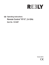
12. Installing the Servos
The installation of a servo (1) always depends on the
particular model used. For specific information, refer to the
design documents of the model.
However, generally you should try to fasten the servos with
screws in such a way that vibrations are minimised.
This is why rubber bushings (2) with metal sleeves (3) are
usually included with the servos.
When servo arms or linkages are obstructed, the servos
cannot assume the required positions. This causes higher
power consumption and the model cannot be controlled
properly.
Always mount the servo lever at a 90° angle to the linkage
rods (see sketch A).
The rudder or steering travel will not be equal on both sides
if the servo lever is mounted at an angle to the linkage rod
(sketches B and C).
3
2
2
1
3
Figure 10
SERVO SERVO
SERVO
A
B
C
Figure 11

33
13. Verification of Steering and Driving Functions
Connect the servos or drive controls used in your model and the power supply to the receiver.
To prevent the model from driving off inadvertently while testing the steering and drive functions, place the
model chassis on a suitable basis (wooden block, etc.). The wheels should turn freely.
a) Verification of the Steering Function
Put the two trimming controls for the drive and steering functions (see figure 2, items 11 and 12) in their central
positions. Turn the dual rate control for the steering function (see figure 2, item 9) counter-clockwise to the stop.
Next, switch on the transmitter and then the
receiver. If everything was connected correctly, the
model steering should react to turns of the steering
wheel (see figure 1, item 2).
When the steering wheel is in its central position,
the model's wheels must point straight ahead.
If the wheels are to be turned even though the
steering wheel is in its central position, loosen the
servo lever and screw it on turned by one "tooth".
If you are steering to the left, the wheels must turn
to the left (see figure 12, sketch A). If you are
steering to the right, the wheels must turn to the
right (see figure 12, sketch B).
If the wheels react opposite to the direction indicated in figure 12, use the steering function reverse switch (see figure
2, item 14) to switch the effective direction of the steering wheel and thus the steering servo rotational direction.
Important!
Set the steering linkages at your model so that they can reach their full deflection to the right and left
without the steering stopping or being limited mechanically. The trimming lever for the steering function
(see figure 2, item 12) must be in the centre position for this.
This way, you can re-trim the model later if it pulls to the left or right when driving straight.
Figure 12

34
Practical advice:
The trimming control for the steering function is exactly at the centre if the servo lever no longer moves if
you try operating the reverse switch. The steering wheel must be in the centre position for this.
If the steering deflection proves to be too large when operating the model, reduce it using the dual rate control for the
steering function (see figure 2, item 9). If you turn the dual rate control clockwise to the right, the steering deflection will
be reduced. Turning the control back to the left will increase the steering deflection again. This setting affects both
sides of the steering deflection.
b) Verification of the Drive Function
When you move the operating lever for the drive
function (see figure 1, item 3) towards the handle
to the stop, the model must accelerate (see figure
13, sketch A).
If you press the lever forwards, the model must
decelerate or switch to reverse driving (see figure
13, sketch B).
If your model's drive reacts opposite to the
indication in figure 13, use the drive function
reverse switch (see figure 2, item 6) to switch the
effective direction of the operating lever.
Important!
In a model with a combustion engine, set the linkage for carburettor and brake linkage so that the throttle/
brake servo is not limited mechanically. The trimming lever for the drive function (see figure 2, item 11)
must be in the centre position for this.
For a model with an electronic speed controller, the different positions of the operating lever fort he drive
function (forwards, stop, reverse) may have to be programmed into the speed controller. Further information
on this can be found in the documents for the speed controller.
When you have verified or set the correct driving and steering function, first switch off the receiver and then the
transmitter.
Your model is now ready for its first test run.
Figure 13

35
14. Binding Function
To enable transmitter and receiver to work together, they must be bound by the same digital code. In the delivery state,
transmitter and receiver are aligned with each other and can be used at once. The binding settings must be renewed
mainly after a replacement of the transmitter or receiver or to remove any interferences.
To perform the binding procedure, proceed as follows:
• Switch off the transmitter.
• Disconnect any connected servos from the receiver.
• Connect the programming plug (1) to the CH3/BIND output
of the receiver.
• Switch on the receiver. The receiver LED (2) starts to flash.
• Press the binding button at the transmitter (see figure 2,
item 8) and keep the button pressed.
• Switch on the transmitter while the button is pressed. The
LED for the under-voltage display flashes.
• When the LED in the receiver (2) stays lit permanently,
the binding procedure is completed.
• Release the binding button at the transmitter.
• Switch off the receiver and transmitter and remove the programming plug.
• Re-connect the servos/controls to the receiver.
• Verify the system functions and perform a range check.
If the system does not work properly, repeat the procedure.
15. Using the Transmitter as a Simulator
If required, you can also use the transmitter for simulations. In this case, you will require the optional USB cable and
suitable computer software.
The USB cable is connected to the rear of the transmitter, using the PC link socket (see figure 3, item 15). If connected
and installed correctly, the remote control is recognised as human interface device and can be used like a common
joystick.
For all further information on this, see the documents for the USB cable.
Figure 14

36
16. Setting the Fail Safe Function
Your remote control receiver offers the option of taking the throttle servo to a certain position if no correct remote
control signal is received any longer in case of an interference.
If the idle position (central position of the operating lever for driving) is selected as a fail safe position, the vehicle
comes to a halt automatically if the radio transmission is interfered with or the model drives out of the remote control’s
range at full throttle. You can also select any brake position (e.g. 50% brake effect) as the fail safe position. In this
case, fix the operating lever for driving in the desired position with a rubber ring when setting the fail safe function.
In order perform the fail safe settings, proceed as follows:
• Take the operating lever for driving to the desired position.
• Switch on the transmitter and then the receiver.
• Right after that, press and hold the receiver button (1).
• The receiver LED (2) on the receiver starts to flash after
approx. 3 seconds.
• When the LED flashes, release the button.
• When the LED is lit again permanently, the fail safe position
is stored.
When using the throttle servo, accelerate a little with the combustion engine out and then switch off the
transmitter. The throttle servo then has to go into the fail safe position immediately. For electronic models
with an electronic speed controller, support the vehicle so that the wheels can turn freely for the test.
Figure 15

37
17. Maintenance and Care
Clean the exterior of the remote control only with a soft, dry cloth or brush. Never use any abrasive cleaning agents or
chemical solutions as these could damage the surfaces of the casings.
18. Disposal
a) General Information
At the end of its service life, dispose of the product according to the relevant statutory regulations.
b) Batteries and Rechargeable Batteries
You as the end user are required by law (Battery Ordinance) to return all used batteries/rechargeable batteries. Disposing
of them in the household waste is prohibited!
Batteries/rechargeable batteries that include hazardous substances are labelled with these icon to indicate
that disposal in domestic waste is forbidden. The descriptions for the respective heavy metal are: Cd =
cadmium, Hg = mercury, Pb = lead (the names are indicated on the battery/rechargeable battery e.g.
below the rubbish bin icon shown to the left).
You may return used batteries/rechargeable batteries free of charge to any collecting point in your local community, in
our stores or everywhere else where batteries/rechargeable batteries are sold.
You thus fulfil your statutory obligations and contribute to the protection of the environment.

38
19. Troubleshooting
Even though the remote control system was built to the state of the art, there can still be malfunctions or faults. For this
reason, we would like to give you some information on how to deal with possible problems.
Problem
The transmitter does not respond.
The servos do not respond.
The servos vibrate.
One servo is humming.
The range of the system is very short.
The transmitter turns off straight away
or after a short while.
Remedy
• Check the batteries or rechargeable batteries in the remote control.
• Check the polarity of the batteries.
• Check the on/off switch position
• Check the batteries in the receiver.
• Test the switch cable.
• Test the BEC function of the speed controller.
• Check the polarity of the servo connector.
• For test purposes, change the receiver.
• Check batteries in the remote control and the receiver.
• Carefully dry any possible dampness in the receiver with a hot air blower.
• Check the batteries in the receiver.
• Make sure the linkage rods run smoothly.
• Operate the servo without the servo arm for test purposes.
• Check batteries in the remote control and the receiver.
• Check the receiver aerial for damage and electrical continuity.
• Install the receiver aerial in a different position in the model for test
purposes.
• Check batteries or rechargeable batteries in the transmitter and replace
if required.

39
20. Technical Data
a) Transmitter
Frequency range: ........................................... 2.4 GHz
Number of channels: ...................................... 2
Supply voltage: ............................................... 9.6 - 12 V/DC using 8 Mignon batteries or rechargeable batteries
Dimensions (W x H x D): ................................ Approx. 159 x 235 x 85 mm
Weight including rechargeable battery: ......... Approx. 534 g
b) Receiver
Frequency range: ........................................... 2.4 GHz
Number of channels: ...................................... 3
Connector system: ......................................... Futaba/JR
Supply voltage: ............................................... 4 - 8.4 V/DC using 4 mignon batteries or rechargeable batteries
(or BEC)
Dimensions (W x H x D): ................................ Approx. 37.5 x 22.5 x 13 mm
Weight:............................................................ Approx. 6 g
21. Declaration of Conformity (DOC)
The manufacturer hereby declares that this product complies with the essential requirements and regulations and all
other relevant provisions of the 1999/5/EC directive.
The declaration of conformity for this product can be found at www.conrad.com.
/