Page is loading ...

User’s Manual
68-550-01 Rev. B
11 08
RGB 168
xixi
xixi
xi
VGA Interface with Stereo Audio and ADSP
™

Precautions
This symbol is intended to alert the user of important
operating and maintenance (servicing) instructions
in the literature provided with the equipment.
This symbol is intended to alert the user of the
presence of uninsulated dangerous voltage within
the product's enclosure that may present a risk of
electric shock.
Caution
Read Instructions • Read and understand all safety and operating
instructions before using the equipment.
Retain Instructions • The safety instructions should be kept for future
reference.
Follow Warnings • Follow all warnings and instructions marked on the
equipment or in the user information.
Avoid Attachments • Do not use tools or attachments that are not
recommended by the equipment manufacturer because they may be
hazardous.
Warning
Power sources • This equipment should be operated only from the power source
indicated on the product. This equipment is intended to be used with a main
power system with a grounded (neutral) conductor. The third (grounding) pin is
a safety feature, do not attempt to bypass or disable it.
Power disconnection • To remove power from the equipment safely, remove all
power cords from the rear of the equipment, or the desktop power module (if
detachable), or from the power source receptacle (wall plug).
Power cord protection • Power cords should be routed so that they are not likely to
be stepped on or pinched by items placed upon or against them.
Servicing • Refer all servicing to qualified service personnel. There are no user-
serviceable parts inside. To prevent the risk of shock, do not attempt to service
this equipment yourself because opening or removing covers may expose you to
dangerous voltage or other hazards.
Slots and openings • If the equipment has slots or holes in the enclosure, these are
provided to prevent overheating of sensitive components inside. These openings
must never be blocked by other objects.
Lithium battery • There is a danger of explosion if battery is incorrectly replaced.
Replace it only with the same or equivalent type recommended by the
manufacturer. Dispose of used batteries according to the manufacturer's
instructions.
Ce symbole sert à avertir l’utilisateur que la
documentation fournie avec le matériel contient des
instructions importantes concernant l’exploitation
et la maintenance (réparation).
Ce symbole sert à avertir l’utilisateur de la présence
dans le boîtier de l’appareil de tensions dangereuses
non isolées posant des risques d’électrocution.
Attention
Lire les instructions• Prendre connaissance de toutes les consignes de
sécurité et d’exploitation avant d’utiliser le matériel.
Conserver les instructions• Ranger les consignes de sécurité afin de
pouvoir les consulter à l’avenir.
Respecter les avertissements • Observer tous les avertissements et
consignes marqués sur le matériel ou présentés dans la documentation
utilisateur.
Eviter les pièces de fixation • Ne pas utiliser de pièces de fixation ni
d’outils non recommandés par le fabricant du matériel car cela
risquerait de poser certains dangers.
Avertissement
Alimentations• Ne faire fonctionner ce matériel qu’avec la source d’alimentation
indiquée sur l’appareil. Ce matériel doit être utilisé avec une alimentation
principale comportant un fil de terre (neutre). Le troisième contact (de mise à la
terre) constitue un dispositif de sécurité : n’essayez pas de la contourner ni de la
désactiver.
Déconnexion de l’alimentation• Pour mettre le matériel hors tension sans danger,
déconnectez tous les cordons d’alimentation de l’arrière de l’appareil ou du
module d’alimentation de bureau (s’il est amovible) ou encore de la prise secteur.
Protection du cordon d’alimentation • Acheminer les cordons d’alimentation de
manière à ce que personne ne risque de marcher dessus et à ce qu’ils ne soient pas
écrasés ou pincés par des objets.
Réparation-maintenance • Faire exécuter toutes les interventions de réparation-
maintenance par un technicien qualifié. Aucun des éléments internes ne peut être
réparé par l’utilisateur. Afin d’éviter tout danger d’électrocution, l’utilisateur ne
doit pas essayer de procéder lui-même à ces opérations car l’ouverture ou le
retrait des couvercles risquent de l’exposer à de hautes tensions et autres dangers.
Fentes et orifices • Si le boîtier de l’appareil comporte des fentes ou des orifices,
ceux-ci servent à empêcher les composants internes sensibles de surchauffer. Ces
ouvertures ne doivent jamais être bloquées par des objets.
Lithium Batterie • Il a danger d'explosion s'll y a remplacment incorrect de la
batterie. Remplacer uniquement avec une batterie du meme type ou d'un ype
equivalent recommande par le constructeur. Mettre au reut les batteries usagees
conformement aux instructions du fabricant.
Safety Instructions • English
Consignes de Sécurité • Français
Sicherheitsanleitungen • Deutsch
Dieses Symbol soll den Benutzer auf wichtige
Anleitungen zur Bedienung und Wartung
(Instandhaltung) in der Dokumentation hinweisen,
die im Lieferumfang dieses Gerätes enthalten ist.
Dieses Symbol soll den Benutzer darauf aufmerksam
machen, daß im Inneren des Gehäuses dieses
Produktes gefährliche Spannungen, die nicht isoliert
sind und die einen elektrischen Schock verursachen
können, herrschen.
Achtung
Lesen der Anleitungen • Bevor Sie das Gerät zum ersten Mal verwenden,
sollten Sie alle Sicherheits-und Bedienungsanleitungen genau
durchlesen und verstehen.
Aufbewahren der Anleitungen • Die Sicherheitsanleitungen sollten
aufbewahrt werden, damit Sie später darauf zurückgreifen können.
Befolgen der Warnhinweise • Befolgen Sie alle Warnhinweise und
Anleitungen auf dem Gerät oder in der Benutzerdokumentation.
Keine Zusatzgeräte • Verwenden Sie keine Werkzeuge oder Zusatzgeräte,
die nicht ausdrücklich vom Hersteller empfohlen wurden, da diese eine
Gefahrenquelle darstellen können.
Vorsicht
Stromquellen • Dieses Gerät sollte nur über die auf dem Produkt angegebene
Stromquelle betrieben werden. Dieses Gerät wurde für eine Verwendung mit
einer Hauptstromleitung mit einem geerdeten (neutralen) Leiter konzipiert. Der
dritte Stift oder Kontakt ist für einen Erdschluß, und stellt eine
Sicherheitsfunktion dar und sollte nicht umgangen oder außer Betrieb gesetzt
werden.
Stromunterbrechung • Um das Gerät auf sichere Weise vom Netz zu trennen,
sollten Sie alle Netzkabeln aus der Rückseite des Gerätes oder aus dem Desktop-
Strommodul (falls dies möglich ist) oder aus der Wandsteckdose ziehen.
Schutz des Netzkabels • Netzkabel sollten stets so verlegt werden, daß sie nicht
im Weg liegen und niemand darauf treten kann oder Objekte darauf- oder
unmittelbar dagegengestellt werden können.
Wartung • Alle Wartungsmaßnahmen sollten nur von qualifiziertem
Servicepersonal durchgeführt werden. Im Inneren des Gerätes sind keine Teile
enthalten, die vom Benutzer gewartet werden können. Zur Vermeidung eines
elektrischen Schocks versuchen Sie in keinem Fall, dieses Gerät selbst zu warten,
da beim Öffnen oder Entfernen der Abdeckungen die Gefahr eines elektrischen
Schlags oder andere Gefahren bestehen.
Schlitze und Öffnungen • Wenn das Gerät Schlitze oder Löcher im Gehäuse
aufweist, dienen diese zur Vermeidung einer Überhitzung der empfindlichen
Teile im Inneren. Diese Öffnungen dürfen niemals von anderen Objekten
blockiert werden.
Litium-Batterie • Explosionsgefahr, falls die Batterie nicht richtig ersetzt wird.
Ersetzen Sie nur durch diegleiche oder einen vergleichbaren Batterietyp, der
auch vom Hersteller empfohlen wird. Entsorgung der verbrauchten Batterien
bitte gemäß den Herstelleranweisungen.
Este símbolo se utiliza para advertir al usuario sobre
instrucciones importantes de operación y
mantenimiento (o cambio de partes) que se desean
destacar en el contenido de la documentación
suministrada con los equipos.
Este símbolo se utiliza para advertir al usuario sobre
la presencia de elementos con voltaje peligroso sin
protección aislante, que puedan encontrarse dentro
de la caja o alojamiento del producto, y que puedan
representar riesgo de electrocución.
Precaucion
Leer las instrucciones • Leer y analizar todas las instrucciones de
operación y seguridad, antes de usar el equipo.
Conservar las instrucciones • Conservar las instrucciones de seguridad
para futura consulta.
Obedecer las advertencias • Todas las advertencias e instrucciones
marcadas en el equipo o en la documentación del usuario, deben ser
obedecidas.
Evitar el uso de accesorios • No usar herramientas o accesorios que no
sean especificamente recomendados por el fabricante, ya que podrian
implicar riesgos.
Advertencia
Alimentación eléctrica • Este equipo debe conectarse únicamente a la fuente/tipo
de alimentación eléctrica indicada en el mismo. La alimentación eléctrica de este
equipo debe provenir de un sistema de distribución general con conductor
neutro a tierra. La tercera pata (puesta a tierra) es una medida de seguridad, no
puentearia ni eliminaria.
Desconexión de alimentación eléctrica • Para desconectar con seguridad la
acometida de alimentación eléctrica al equipo, desenchufar todos los cables de
alimentación en el panel trasero del equipo, o desenchufar el módulo de
alimentación (si fuera independiente), o desenchufar el cable del receptáculo de
la pared.
Protección del cables de alimentación • Los cables de alimentación eléctrica se
deben instalar en lugares donde no sean pisados ni apretados por objetos que se
puedan apoyar sobre ellos.
Reparaciones/mantenimiento • Solicitar siempre los servicios técnicos de personal
calificado. En el interior no hay partes a las que el usuario deba acceder. Para
evitar riesgo de electrocución, no intentar personalmente la reparación/
mantenimiento de este equipo, ya que al abrir o extraer las tapas puede quedar
expuesto a voltajes peligrosos u otros riesgos.
Ranuras y aberturas • Si el equipo posee ranuras o orificios en su caja/alojamiento,
es para evitar el sobrecalientamiento de componentes internos sensibles. Estas
aberturas nunca se deben obstruir con otros objetos.
Batería de litio • Existe riesgo de explosión si esta batería se coloca en la posición
incorrecta. Cambiar esta batería únicamente con el mismo tipo (o su equivalente)
recomendado por el fabricante. Desachar las baterías usadas siguiendo las
instrucciones del fabricante.
Instrucciones de seguridad • Español

FCC Class A Notice
This equipment has been tested and found to comply with the limits for a
Class A digital device, pursuant to part 15 of the FCC Rules. These limits are
designed to provide reasonable protection against harmful interference when the
equipment is operated in a commercial environment. This equipment generates,
uses and can radiate radio frequency energy and, if not installed and used in
accordance with the instruction manual, may cause harmful interference to radio
communications. Operation of this equipment in a residential area is likely to
cause harmful interference, in which case the user will be required to correct the
interference at his own expense.
N This unit was tested with shielded cables on the peripheral devices. Shielded
cables must be used with the unit to ensure compliance.


RGB 168
xixi
xixi
xi • Table of Contents
Table of Contents
Chapter 1 • Introduction .......................................................... 1-1
About this Manual ................................................................ 1-2
About the RGB 168
xixi
xixi
xi ............................................................. 1-2
Features ...................................................................................... 1-2
Chapter 2 • Installation and Operation.......................... 2-1
Installation Overview ......................................................... 2-2
Front Panel ................................................................................ 2-3
Rear Panel ................................................................................. 2-5
Setting Internal Jumpers ................................................... 2-8
Installing Adapter Plates ................................................ 2-10
Mounting the Interface ....................................................2-13
Tabletop/desktop placement ..............................................2-13
Under-desk mounting ......................................................... 2-13
Through-desk mounting ...................................................... 2-14
UL rack mounting guidelines ...............................................2-15
Rack mounting .....................................................................2-16
Cabling ......................................................................................2-17
Troubleshooting....................................................................2-20
Appendix A • Specifications, Accessories, and Part
Numbers .............................................................................................. A-1
Specifications ......................................................................... A-2
Included Parts ......................................................................... A-5
Accessories .............................................................................. A-5
Cables ......................................................................................... A-5
Adapter Plates ....................................................................... A-7
68-550-01 Rev. B
11 08
All trademarks mentioned in this manual are the properties of their respective
owners.
TOC-i

Table of Contents, cont’d
RGB 168
xixi
xixi
xi • Table of Contents
TOC-ii

1
Chapter One
Introduction
About this Manual
About the RGB 168xi
Features
RGB 168
xixi
xixi
xi

Introduction, cont’d
RGB 168
xixi
xixi
xi • Introduction
Introduction
About this Manual
This manual contains information about the RGB 168xi
universal analog interface and how to operate and
configure it.
About the RGB 168
xixi
xixi
xi
The RGB 168xi is a computer-video and stereo audio
interface with 300 MHz (-3dB) video bandwidth. This
interface has a horizontal frequency range of 15 kHz to
125 kHz, so it can be used with any type of analog
computer signal, including those from VGA to UXGA-2,
Mac, Quadra, Sun, and SGI computers.
Features
This section highlights the main features of the RGB 168xi
interface. See the installation chapter for a detailed
description of front and rear panel features.
Internal power supply — Uses a standard IEC power cord.
Front panel AC outlet — Peripherals or laptop computers
can be plugged into the unswitched front panel AC
outlet for a convenient power connection. This
feature is not available in Europe.
Furniture and rack mountability — The RGB 168xi can be
mounted under a desk or podium with optional
hardware, or it can be mounted in a rack or through
a desk or other furniture with included vertical
mounting brackets.
Active stereo audio — Unbalanced stereo audio input via a
front panel jack is output as balanced, line level
stereo audio on the rear panel captive screw
connector.
Horizontal shift control — The interface features front
panel horizontal centering control.
Sync stripping — Incoming sync will be stripped from the
red, green, and blue signals.
RGBHV, RGBS, or RGsB output — RGBHV can be output
simultaneously with RGBS. Sync on green (RGsB)
output can be DIP switch selected.
Advanced Digital Sync Processing
™ (ADSP™) — ADSP
allows sync processing operations, such as horizontal
centering, to occur without affecting the signal’s sync
timing. This allows horizontal centering to be
applied to signals that are output to digital display
1-2

RGB 168
xixi
xixi
xi • Introduction
devices such as LCD projectors, DLP projectors and
plasma displays. A rear panel DIP switch allows an
alternative, Digital Display Sync Processing™
(DDSP™), to be used instead.
Gain/peaking control — To compensate for signal
degradation caused by long cable lengths, use this
rear panel toggle switch to increase output voltages.
Serration pulse — This feature allows serration pulses to
either be present or not present at the output.
Serration pulses are required for some displays.
Pass-through connectors — A wide assortment
of architectural adapter plates is available for
installation on these interfaces to allow convenient
pass-through A/V connections.
Buffered local monitor output — A 15-pin HD female
connector provides a front panel buffered output for
a local monitor.
ID bit termination — Two front panel DIP switches
provide ID bit termination on pins 4 and/or 11 of the
local monitor output.
1-3

Introduction, cont’d
RGB 168
xixi
xixi
xi • Introduction
1-4

RGB 168
xixi
xixi
xi • Installation and Operation
2
Chapter Two
Installation and Operation
Installation Overview
Front Panel
Rear Panel
Setting Internal Jumpers
Installing Adapter Plates
Mounting the Interface
Cabling
Troubleshooting
RGB 168
xixi
xixi
xi

RGB 168
xixi
xixi
xi • Installation and Operation
Installation and Operation, cont’d
Installation and Operation
Installation Overview
To install and set up the RGB 168xi for operation, follow
these basic steps:
1
Turn all of the equipment off. Make sure that the
computer, the interface and the output device(s)
(projector or display monitor, and local monitor) are
all turned off and disconnected from the power
source.
2
Set internal jumpers for sync polarity and sync pulse
width. See “Setting Internal Jumpers” in this chapter.
3
Install optional adapter plates for pass-through A/V
connections. See “Installing Adapter Plates” in this
chapter.
4
Install the rubber feet for tabletop use, or install the
appropriate brackets and furniture or rack mount the
interface. See “Mounting the Interface” in this
chapter.
5
Attach the input (computer) and output (display, local
monitor and audio) cables. See “Cabling” in this
chapter.
6
Set the DIP and toggle switches. Use the “Front
Panels” and “Rear Panels” sections of this chapter as
a guide.
7
Connect power cords and turn on the devices in the
following order: output devices (projector, monitors,
speakers) and input device (computer).
8
The image should appear on screen, and sound
should be audible. If not, ensure that all devices are
plugged in and receiving power. Check the cabling
and switch settings, and make adjustments as
needed.
Refer to “Troubleshooting” in this chapter, then call
the Extron customer support hotline, if needed.
2-2

RGB 168
xixi
xixi
xi • Installation and Operation
Front Panel
This section familiarizes you with the front panel features
and the options for making connections and changing
settings.
Setting DIP switches
The DIP switches on the front and rear panels of the
RGB 168xi may be either the rocking type or the sliding
type.
To set rocking type DIP switches, use a
small screwdriver to depress the
appropriate end of each switch.
To set sliding type DIP switches, use a small
screwdriver to slide (push) the switch to the
On/closed or Off/open position.
1
2-color power/signal LED — This LED lights amber
to indicate power on only. It lights green to indicate
that power is on and a video signal is also present.
2
Audio input jack — This 3.5 mm stereo input jack
accepts an unbalanced stereo audio input.
3
Analog video input 15-pin HD female connector
4
ID bit termination DIP switches — These switches
provide proper ID bit termination when a local
monitor is not connected to the interface’s
buffered local monitor output.
DIP switch 1 connects pin 4 to ground.
DIP switch 2 connects pin 11 to ground.
ON — Set both switches (ID PIN 4 and
ID PIN 11) to On if no local monitor is
connected.
OFF — Set both switches to Off if a local
monitor is attached to the interface.
3 41
2
3 412
2-3
ID PIN 4
ID PIN 11
UNSWITCHED
100-240 0.5A MAX.
RGB 168
H. SHIFT
MIN/MAX
INPUTS
AUDIO ANALOG
BUFFERED LOCAL
MONITOR OUTPUT
UNIVERSAL INTERFACE W/ADSP
ID PIN 4
ID PIN 11
1
3
5
7
8 9
2
6
4

RGB 168
xixi
xixi
xi • Installation and Operation
Installation and Operation, cont’d
2-4
5
Buffered local monitor output 15-pin HD female
connector — This allows output to a local monitor.
Set the ID PIN DIP switches to On if this connector is
not used.
6
Horizontal shift control knob — This control adjusts
the horizontal centering of the remote output
display.
The horizontal shift control has no mechanical limits
to rotation. When the minimum or maximum limit
of the control is reached, the picture ceases to move
on screen, and the MIN/MAX indicator LED lights
red.
If the DDSP DIP switch is set to On, the horizontal
shift control is disabled.
7
MIN/MAX indicator LED — This LED lights red
whenever the lower or upper limits of the horizontal
or vertical shift controls are reached.
8
Optional architectural adapter plates — Up to four
adapter plates for pass-through audio/video
connections can be attached at one time to the
interface. See the “Installing Adapter Plates” section
in this chapter for installation instructions.
9
AC power output connector — An unswitched
standard IEC AC power connector allows you to
connect a peripheral device that requires power. This
feature is not available in Europe (RGB 168xi Int).

RGB 168
xixi
xixi
xi • Installation and Operation 2-5
3
SOG
DDSP
SERR
SPARE
100-240 50/60 Hz 0.5A
OUTPUT
R
H
G
V
B
S
UNITY
50%
100%
GAIN/
PEAK
1 2 5 72 64
Rear Panel
1
AC power input connector — Connect a standard
IEC AC power cord here for power
input (100 VAC to 240 VAC, 50/60 Hz).
2
Cable access openings — Cables attached to the
front panel A/V pass-through architectural adapter
plates exit the enclosure here. Clamp cables in place
with the supplied hardware.
3
Optional output architectural adapter plate — Front
panel input AAP A/V connectors can be wired here
to pass-through output connectors.
4
3-position gain/peaking switch — Use this toggle
switch to compensate for signal degradation caused
by long (over about 125 feet) cable lengths. Choose
the setting that provides the best image on the
output display device. Select from these options:
• Unity (no gain or peaking) — The output level is
the same as that of the input and with no
added peaking.
• 50% — This setting increases the output signal
level and adds 50% of the maximum peaking
to the signal.
• 100% — This setting increases the output signal
level and adds 100% of the maximum peaking
to the signal.
If the signal cable between the interface and the
display device is shorter than 125 feet, and the gain/
peak switch is set to a setting other than unity, the
image may be overly bright (overcompensated).

RGB 168
xixi
xixi
xi • Installation and Operation
Installation and Operation, cont’d
2-6
If the edges of the image seem to exceed their
boundaries or if thin lines and sharp edges look
thick and fuzzy, try changing the gain/peak setting.
5
DIP switches — The four DIP switches on
the rear panel control sync on green (SOG)
output, Digital Display Sync Processing and
serration pulse removal.
The fourth switch is a spare and it has no function.
1 — SOG (sync on green)
ON — When this switch is set to On, the
interface outputs sync on green.
OFF — When the SOG switch is set to Off, the
interface outputs both separate
horizontal and vertical sync (on the H
and V connectors) and composite sync
(on the S connector) for RGBHV or
RGBS, respectively.
2 — DDSP
™
(Digital Display Sync Processing
™
)
This feature may be necessary for digital display
devices such as LCD (liquid crystal display), DLP
(digital light processing) and plasma displays.
Use this option if the image still is not displayed
properly after all other options, such as serration
pulse removal and video termination changes,
have been explored.
ON — When this switch is set to On, the
interface uses Digital Display Sync
Processing instead of Advanced Digital
Sync Processing™. DDSP does not
process the sync signal.
DDSP disables horizontal and vertical shift
controls.
OFF — When this switch is set to Off, the
interface performs sync processing
operations, such as horizontal shifting,
with ADSP.
SOG
DDSP
SERR
SPARE

RGB 168
xixi
xixi
xi • Installation and Operation 2-7
3 — SERR (serration pulse) — Many display
devices, including LCD and DLP projectors and
plasma displays, must have serration pulses
removed from the sync signal in order to display
properly. Flagging or bending at the top of the
video image is a sign that the serration pulses
should be removed.
ON — When this switch is set to On, serration
pulses are output in the vertical sync
interval.
OFF — When this switch is set to Off, serration
pulses are not output.
4 — SPARE — This DIP switch does not have a
function.
6
BNC output connectors — These BNC female
connectors are for red, green, and blue video output,
and horizontal, vertical and composite sync output.
7
Stereo audio output connector — This 3.5 mm,
5-conductor captive screw connector is used for
audio output. See “Cabling” in this chapter for a
wiring guide.

RGB 168
xixi
xixi
xi • Installation and Operation
Installation and Operation, cont’d
Setting Internal Jumpers
The jumpers inside the interface(s) are set at the factory to meet
the requirements of most systems. However, you can
change a jumper setting to meet the needs of a particular
system.
Changes to internal jumper settings must be
performed by authorized service personnel only.
The user-configurable, internal jumpers control the
following functions:
• horizontal and vertical sync polarity, and
• vertical sync pulse width.
Follow these steps to change the jumper settings.
1. Remove power from the interface (if it is connected) by
disconnecting the AC power cord from the unit.
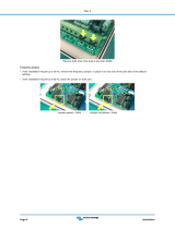
2. Open the cover of the interface (the top half of the
enclosure), as shown below.
Do not touch any switches or electronic
components inside the interface. Doing so
could damage the interface.
Opening the interface cover
3. Note the positions of jumpers J20 and J40 before
changing jumper settings. The following illustration of
the circuit board shows the locations of the J20 and J40
jumpers. There are two possible setting combinations
for 3-pin jumpers:
Extron
RGB 168xi
RGB 168 xi
INPUTS
AUDIO
ANALOG
UNSWITCHED
600 WATTS MAX.
MIN/MAX
UNIVERSAL INTERFACE W /ADSP
ID PIN 14
ID PIN 11
BUFFERED LOCAL
MONITOR OUTPUT
Remove #8 Screw
(4 Plcs) Each Side
and Bracket, if Present
Remove (12)
Screws
Lift Cover
Straight Up
2-8

RGB 168
xixi
xixi
xi • Installation and Operation 2-9
Negative
F
ollow
1
1 and 2
2 and 3
J19
1
J40
1
J20
1
Front
Rear
Power Supply
J20: Sync
polarity
jumper
J40: Vertical
sync
width
jumper
pins 1 and 2 connected, and
pins 2 and 3 connected.
Circuit board jumper locations
4. Configure the jumpers. To configure the jumpers, use
pliers to pull the jumper shunt off the pins, then place
the jumper on the appropriate pins.
Changing jumper settings
The jumpers perform the following functions:
J-20: Sync polarity jumper — This jumper adjusts the
output sync polarity. Horizontal (H) and vertical
(V) sync output can either follow input sync
polarity, or be forced to negative.

RGB 168
xixi
xixi
xi • Installation and Operation
Installation and Operation, cont’d
2-10
• If the jumper is placed on pins 1 and 2, output
H and V sync polarities are forced to negative.
• If the jumper is placed on pins 2 and 3, output
sync polarities follow input sync polarity: the
output sync signals’ polarity are the same as
the input polarity.
This is the default setting.
J-40: Vertical sync width jumper — This jumper
adjusts the vertical sync pulse width. Some
digital display devices have very specific
requirements for incoming sync pulse width. If
no picture displays, the picture cuts in and out,
or the picture is scrambled, try adjusting the
vertical sync pulse width or switching from
ADSP to DDSP.
• If the jumper is placed on pins 1 and 2, the
output vertical sync pulse is
short (narrow).
• If the jumper is placed on pins 2 and 3, the
output vertical sync pulse iswide. This is the
default setting.
5. Replace and fasten the enclosure cover, reversing step 2.
If adapter plates will be installed next, this step can be
omitted.
Installing Adapter Plates
The RGB 168xi offers the ability to incorporate a variety of
optional architectural adapter plates for pass-through audio
and/or video connections. Each interface’s front panel can
hold up to four (4) input adapter plates. The rear panel can
hold up to two (2) output adapter plates.
Blank plates (three double height) are included with the
interface to cover unused spaces. Other adapter plates
must be ordered separately.
The input plates attach to the front panel. Output cables,
attached to the rear of each plate, pass through the interface
enclosure and rear panel and are held in place by clamps or,
where an output plate is installed, may be wired directly to
the rear output plate connectors. Some adapters require
cables to be soldered to the input/output plate connectors.
Adapter plates should be attached to the output cables and
interface before the interface is installed in a rack or in
furniture. The screws for installing the adapter plates are
built into the plates, so no additional screws are needed.
Wide
S
hort
1
/