
EN2H-0220GE51 R0308
Heating Controller SDC
Remote Heating Controller DHC
OPERATING INSTRUCTIONS

EN2H-0220GE51 R0308

SDC / DHC Contents
EN2H-0220GE51 R0308 3
Contents
1 Software version ............................................................................................................. 7
2 Safety instructions.......................................................................................................... 7
2.1 Intended use ........................................................................................................ 7
2.2 Requirements for start-up .................................................................................... 7
2.2.1 Power supply........................................................................................... 8
2.2.2 Connection conditions............................................................................. 8
2.2.3 Cable cross-sections............................................................................... 8
2.2.4 Maximum cable lengths .......................................................................... 8
2.2.5 Cable installation..................................................................................... 8
2.2.6 Grounding and zeroing............................................................................ 9
2.3 Hot-water temperature greater than 60 °C .......................................................... 9
2.4 Connection of accessory parts .......................................................................... 10
2.5 Maintenance and cleaning................................................................................. 10
3 Overview ........................................................................................................................11
4 Operation .......................................................................................................................12
4.1 Display and operating elements ........................................................................ 12
4.1.1 Display (basic display) .......................................................................... 13
4.1.2 Operating elements............................................................................... 14
4.1.2.1 Input button (press / turn) ........................................................ 14
4.1.2.2 "Daytime room temperature" button........................................ 14
4.1.2.3 "Night-time room temperature" button..................................... 15
4.1.2.4 "Daytime hot-water temperature" button ................................. 15
4.1.2.5
"Operating mode" button (basic display)................................. 16
4.1.2.6 "Switching time programs / Holiday programs" button............ 23
4.1.2.7 "System information" button.................................................... 26
4.1.2.8 "Manual mode" / "Emission measurement" button ................. 28
4.1.2.9 Heating curve .......................................................................... 30
4.2 Menu-selection level .......................................................................................... 31

Contents SDC / DHC
4 EN2H-0220GE51 R0308
4.2.1 "Time - Date" menu............................................................................... 33
4.2.2 "Timeprograms" menu .......................................................................... 34
4.2.2.1 Selection of the control circuit ................................................. 35
4.2.2.2 Selection of the program ......................................................... 35
4.2.2.3 Selection of day of the week and cycle ................................... 35
4.2.2.4 Programming switching times and cycle temperatures........... 36
Block programming...............................................................................................................44
4.2.3 "System Parameters" menu .................................................................. 51
4.2.3.1 Language selection ................................................................. 51
4.2.3.2 Time program .......................................................................... 52
4.2.3.3 Operating mode....................................................................... 52
4.2.3.4 Summer / Heating limit ............................................................ 54
4.2.3.5 Parameter reset....................................................................... 55
4.2.4 "DHW" menu ......................................................................................... 56
4.2.4.1 Night-time hot-water temperature ........................................... 56
4.2.4.2 Legionella protection day ........................................................ 56
4.2.5 "Direct Heating Circuit" / "Mixed Heating Circuit 1" / "Mixed
Heating Circuit 2" menu ........................................................................ 57
4.2.5.1 Reduced operation .................................................................. 57
4.2.5.2 Heating system........................................................................ 58
4.3 Error messages.................................................................................................. 59
5 Log.................................................................................................................................. 60

SDC / DHC Contents
EN2H-0220GE51 R0308 5


SDC / DHC Software version
EN2H-0220GE51 R0308 7
Pos: 1 /156-Honeywell/Softwareversion/Softwareversion @ 0\mod_1207134342657_6.doc @ 9090
1 Software version
This documentation is valid for software version V 3.0 of your
control device. The software version is displayed after switch-on
for approx. 8 s. If you are using an older software version, please
contact your heating technician.
Pos: 2 /156- Honeywe ll/Sich erheitsh inweis e/Sicher heitsh inweise @ 0\mod_1 2071344 14454_6 .doc @ 9105
2 Safety instructions
2.1 Intended use
The SDC / DHC Smile family of controllers was designed for the
sole purpose of regulating and controlling hot-water, heating and
district heating systems (including hot-water production) that do
not exceed a maximum flow temperature of 120 °C.
2.2 Requirements for start-up
ATTENTION
The heating system must be complete and filled with water
so that the pumps do not run dry and the heating boiler is not
damaged.
The control equipment must be installed in accordance with
the installation instructions.
All electrical connections (voltage supply, burner, mixer
motor, pumps, sensor wiring etc.) must be carried out by the
technician in accordance with the applicable VDE regulations
and correspond with the circuit diagrams.
If floor heating is connected, a limiting thermostat must also
be installed in the flow line after the heating circuit pump.
This switches off the pumps at excessive flow temperatures.
Before starting up the controller, have the heating technician
check all requirements listed above.
The current time and date are already set at the factory and are
backed up by a battery.
The time switch functions based on a basic program and the
control functions are preset for common heating systems with low-
temperature boilers.
NOTE

Safety instructions SDC / DHC
8 EN2H-0220GE51 R0308
2.2.1 Power supply
Do not disconnect the controller from the mains supply!
The battery for saving all individualised data is otherwise
unnecessarily strained. The frost-protection function of the
controller is deactivated.
2.2.2 Connection conditions
All electrical connection work may only be carried out by qualified
personnel!
2.2.3 Cable cross-sections
1.5 mm
2
for all cables carrying 230 V (power supply, burner,
pumps, actuator).
0.6 mm
2
for bus cables (recommended type J-Y(St)Y 2 x 0.6)
0.5 mm
2
for sensors, selectors and analog signal cables.
2.2.4 Maximum cable lengths
Sensor, selector and analog inputs
We recommend using cables no longer than 200 m. Longer
connection lines could be used, but increase the risk of
interference.
Relay outputs
Unlimited cable length.
Bus connections
Max. length of 100 m from the first bus subscriber to the last one
(incl. wall modules).
2.2.5 Cable installation
Install cables for sensors apart from the cables carrying 230 V!
Branch boxes in the sensor cable must be avoided!

SDC / DHC Safety instructions
EN2H-0220GE51 R0308 9
2.2.6 Grounding and zeroing
Local regulations on the connection of equipment must be
observed!
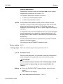
2.3 Hot-water temperature greater than 60 °C
ATTENTION
Note that there is a danger of scalding at all hot-water draw-
off points (kitchen, bathroom etc.) in the following cases.
Add sufficient cold water in these cases.
When the automatic anti-legionella mechanism is activated, the
hot water is automatically heated to the anti-legionella
temperature (65 °C at the factory) on the selected day and at the
selected time to kill any legionella bacteria found in the hot-water
tank.
In the manual mode / emission measurement operating mode, the
hot water is heated up to the highest possible boiler temperature,
as the burner and all pumps are switched on and the mixer is
opened fully. There is an acute danger of scalding at all
connected hot-water draw-off points! Add sufficient cold water or
switch off the hot-water loading pump (at the switch of the pump,
if present). Heating and hot water are in unregulated continuous
operation. This operating mode is for special use by the chimney
sweep for emission measurement or if the controller is defective.
The high hot-water temperatures can be prevented, however, by
setting the boiler thermostat to a max. boiler temperature of
approx. 60 °C.
Automatic anti-
legionella mechanism
Manual mode
/
Emission
measurement

Safety instructions SDC / DHC
10 EN2H-0220GE51 R0308
2.4 Connection of accessory parts
WARNING
According to VDE 0730, a separator for each mains terminal
is to be provided in the voltage supply to the control
equipment. Observe the local regulations regarding
grounding and zeroing.
As soon as the mains voltage is applied to terminals 21, 22,
2, 6, 12 and 18, headers X3 and X4 can also carry mains
voltage.
If the heating circuit and hot-water loading pumps do not
have an On / Off switch, but manual switch-on and switch-off
capability is still desired, the appropriate switches must be
installed by the customer. All accessory parts (sensors,
selectors etc.) are to be connected to the respective circuit
diagram.
2.5 Maintenance and cleaning
The controller is maintenance-free. The device can be cleaned
externally with a moist (not wet) cloth.
Pos: 3 /156- Honeywel l/Bedie nung/Uebe rsich t @ 1\mod _1207643 459088_ 6.doc @ 918 0

SDC / DHC Overview
EN2H-0220GE51 R0308 11
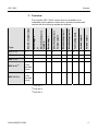
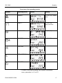
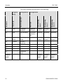
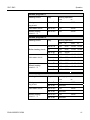
3 Overview
The modular SDC / DHC control device is available in an
installable switch cabinet version and a surface-mounted wall
version with the following equipment features:
Type
Number of output relays
Burner stage 2
or
District heating valve
CLOSED
Burner stage 1
Direct heating circuit
Variable output 3
Mixed heating circuit 1
Mixed heating circuit 2
Tank loading pump
Variable output 2
Variable output 1
SDC 3-10
3 – x x – – x –
SDC 3-40
3 – – – x – – – –
SDC 7-21
1)
7 – x x x – x – –
SDC 9-21
2)
7
+ two
variable
relays
x x x x – x x x
SDC 12-31
3)
10
+ two
variable
relays
x x x x x x x x
1)
DHC 43-1
2)
DHC 43-2
3)
DHC 43-3
Pos: 4 /156- Honeywe ll/Bedie nung/Anze igen_ und_Bedie neleme nte @ 1\m od_120 76435914 94_6.doc @ 9195

Operation SDC / DHC
12 EN2H-0220GE51 R0308
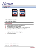
4 Operation
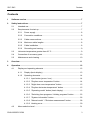
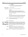
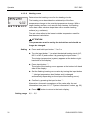
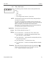
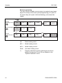
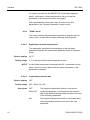
4.1 Display and operating elements
1011
2
1
3
4
7
6
8
9
5
1 "Manual mode" / "Emission measurement" button (not on
district heating controllers)
2 "Operating modes" button (basic display)
3 "Switching time programs" / "Holiday programs" button
4 "System information" button
5 Display
6 Cover clip for service socket
7 "Daytime room temperature" button
8 "Night-time room temperature" button
9 "Daytime hot-water temperature" button
10 Input button (press / turn)
11 Operating mode symbols (heating programs)
Pos: 5 /156- Honeywel l/Bedie nung/Dis play_G rundanzei ge @ 1\m od_120 76436479 63_6.doc @ 9210

SDC / DHC Operation
EN2H-0220GE51 R0308 13
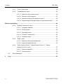
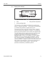
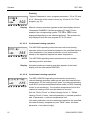
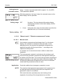
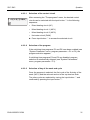
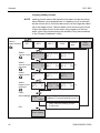
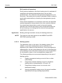
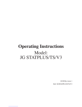
4.1.1 Display (basic display)
1
2
3
4
5
C
1 Day of the week / Date 4 Operating mode symbols
2 Time 5 Heat generator temperature
3 Active operating mode
The illumination of the display is switched on by pressing any
button or using the input button
î and switches off automatically
if no buttons are pressed for a longer period of time.
During start-up of the unit and after a power failure, a segment
test with automatic fault diagnosis is carried out. The respective
device type and the software version number then appear briefly.
The basic display that then appears shows the day of the week,
the date, the time and the heat generator temperature in
automatic mode. Different values appear in the basic display
depending on the set operating mode (AUTOMATIC, PARTY
etc.). Thus, for example, in the ABSENT operating mode, the
indication ABSENT TIL appears instead of the date and the return
date instead of the temperature. Active summer deactivation is
indicated by a beach umbrella symbol
À, and active frost
protection is indicated by a snowflake symbol
Á.
Pos: 6 /156- Honeywel l/Bedie nung/Bed ienele mente @ 1\mod_12 07643735 744_6. doc @ 9225

Operation SDC / DHC
14 EN2H-0220GE51 R0308
4.1.2 Operating elements
Pos: 7 /156- Honeywe ll/Bedie nung/Ei ngabekn opf @ 1\m od_1207 64376813 5_6.do c @ 9240
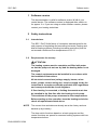
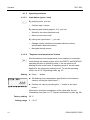
4.1.2.1 Input button (press / turn)
By pressing once, you can:
• Confirm input / values
By pressing and holding (approx. 3 s), you can:
• Switch to the menu-selection level
• Move up one menu level
By turning the input button î, you can:
• Change values (clockwise increases called-up values,
anticlockwise decreases them)
• Navigate through menus
Pos: 8 /156-Honeywell/Bedienung/Taste_Tages-Raumtemperatur @ 1\mod_1207643818525_6.doc @ 9255
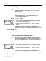
4.1.2.2 "Daytime room temperature" button
Sets the desired room temperature (room setpoint) in automatic
mode during the heating cycles and in the PARTY and HEATING
operating modes. In operating mode 1, the set value for all
heating circuits is the same. In operating mode 2, the set value
applies for the respective heating circuit. To set the operating
mode, see 4.2.3.3 Operating mode, pg. 52.
► Press ¥ button.
► Set flashing room temperature specification to the desired
value by turning the input button
î.
► Confirm set value by pressing the
¥ button or the input
button
î.
Alternative: Automatic acceptance of the value after the set
information time (see 4.1.2.7 "System information" button, pg. 26).
20 °C
5 ... 30 °C
Pos: 9 /156- Honeywel l/Bedie nung/Ta ste_Nach t-Raum temperat ur @ 1\mod _120764 3918822 _6.doc @ 9270
ð
¥
Setting
C
Factory setting
Setting range

SDC / DHC Operation
EN2H-0220GE51 R0308 15
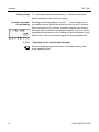
4.1.2.3 "Night-time room temperature" button
Sets the lowered room temperature in automatic mode between
the heating cycles and in the ABSENT and RED. HEATING
operating modes.
In operating mode 1, the set value for all heating circuits is the
same. In operating mode 2, the set value applies for the
respective heating circuit. To set the operating mode, see
4.2.3.3 Operating mode, pg. 52.
► Press ¦ button.
► Set flashing room temperature specification to the desired
value by turning the input button
î.
► Confirm set value by pressing the
¦ button or the input
button
î.
Alternative: Automatic acceptance of the value after the set
information time (see 4.1.2.7 "System information" button, pg. 26).
16 °C
5 ... 30 °C
Pos: 10 /156 -Hon eywell /Bedi enung /Tas te_ Warmwa sser tempera tur @ 1\mod _1207 6439 63713 _6.do c @ 9285
4.1.2.4 "Daytime hot-water temperature" button
Sets the daytime hot-water temperature during the hot-water
operational-readiness times in automatic mode and in the PARTY
and HEATING operating modes. This set value also applies for
exclusively hot-water operation (manual summer operation).
► Press § button.
► Set flashing hot-water temperature to the desired value by
turning the input button
î.
► Confirm set value by pressing the
§ button or the input
button
î.
Alternative: Automatic acceptance of the value after the set
information time (see 4.1.2.7 "System information" button, pg. 26).
50 °C
¦
Setting
C
Factory setting
Setting range
§
Setting
C
Factory setting

Operation SDC / DHC
16 EN2H-0220GE51 R0308
5 °C (hot-water economy temperature) ... Maximum hot-water
heater temperature limit (service setting)
Pressing and holding (approx. 3 s) the § button brings you to
the reload function, where the reload time can be set in minutes.
With a reload time of 0 minutes, loading is started once and the
hot-water tank is loaded to the daytime setpoint. The time for this
superimposed hot-water circuit loading can be set between 0 and
240 minutes. The current week program is superimposed here.
Pos: 11 /156-Honeywell/Bedienung/Taste_Betriebsart @ 1\mod_1207644003760_6.doc @ 9300
4.1.2.5 "Operating mode" button (basic display)
Sets the operating mode and returns to the basic display from
every operating level.
Setting range
One-time hot-wate
r
circuit loading

SDC / DHC Operation
EN2H-0220GE51 R0308 17
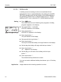
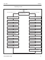
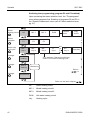
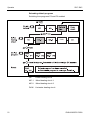
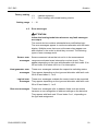
Overview of the operating modes
Symbol Operating mode Display Setting
ç
ABSENT P1 (P2, P3)*, return
date
è
PARTY P1 (P2, P3)*,
party end time
é
AUTOMATIC
C
P1 (P2, P3)*
ê
SUMMER
C
P1(P2, P3)*
ë
HEATING
C
ì
RED. HEATING
C
í
STANDBY
C
* P2 and P3 only after enabling, see "System Parameters"
menu, parameter 2 = P1 to P3

Operation SDC / DHC
18 EN2H-0220GE51 R0308
The selected operating mode appears in plain text, whereby a
marking at the bottom edge of the display points to the respective
operating mode symbol at the same time. In operating mode 1,
the set value for all heating circuits is the same. In operating
mode 2, the set value applies for the respective heating circuit. To
set the operating mode, see 4.2.3.3 Operating mode, pg. 52.
► Press button.
► Select operating mode by turning the input button
î. The
marking is located above the corresponding operating mode
symbol.
► Confirm set operating mode by pressing the
button or the
input button
î.
► With short-term operating modes (ABSENT, PARTY), set the
desired value by turning the input button
î and confirm with
the
button or the input button î.
Alternative: Automatic acceptance of the value after the set
information time (see 4.1.2.7 "System information" button, pg. 26).
Press the button for approx. 3 s
to return to the basic display
from any operating level.
Holiday mode is set via the "Switching time programs / Holiday
programs" button (see 4.1.2.6 "Switching time programs / Holiday
programs" button, pg. 23).
Pos: 12 /156 -Hon eywell /Bedi enung /Abw esenh eits betr ieb @ 1 \mod_1 207644 13735 3_6 .doc @ 9330
4.1.2.5.1 Absence mode (short-term program)
With the ABSENT operating mode, heating operation is
temporarily deactivated and protected from frost during brief
absences. During the absence, all heating circuits are adjusted to
the specified lowered room temperature. Once the set time
expires, the heating circuits automatically return to the operating
mode that was active before the switch to the absence operation.
Short-term programs such as PARTY or ABSENT are skipped
here.
See 4.1.2.5 "Operating mode" button (basic display) , pg. 16
Short absence while heating operation is active.
Setting
Return to the basic
display
NOTE
Setting
Application

SDC / DHC Operation
EN2H-0220GE51 R0308 19
An active absence program can be cancelled in case of early
return.
► Press
button.
► Turn input button
î and switch to automatic operation.
The active absence program has been cancelled.
P1 as from activation
P1 (P2, P3) / 0.5 to 24 h to the current time
P1 (P2, P3)
Program-controlled resumption of heating operation. After
activation of the absence program, heating operation is
interrupted until the following switch-on time of the current
automatic program P1 (or P2 or P3, if enabled).
0,5 ... 24 h
The set value is added on to the current time and represents the
return time. When the absence program is called up again, the
last set value is saved and suggested as the initial value.
An active absence program appears in the basic display with
information on the return time.
Pos: 13 /156-Honeywell/Bedienung/Partybetrieb @ 1\mod_1207644211166_6.doc @ 9345
4.1.2.5.2 Party mode (short-term program)
Party mode causes one-time intermediate heating of all heating
circuits up to a specified point in time and bridges an upcoming or
already active absence cycle totally or partially. Once the set time
expires, the heating circuits automatically return to the operating
mode that was active before the party program. Short-term
programs such as ABSENT or PARTY are skipped here.
See 4.1.2.5 "Operating mode" button (basic display) , pg. 16
One-time extension of heating operation or intermediate heating
during lowering operation outside the schedule.
An active party program can be cancelled early.
Cancellation
Factory setting
Setting range
Display
Setting
Application
Cancellation

Operation SDC / DHC
20 EN2H-0220GE51 R0308
► Press
button.
► Turn input button
î and switch to automatic mode.
The active party program has been cancelled.
P1 as from activation
P1 (P2, P3) / 0.5 to 24 h to the current time P1
P1 (P2, P3)
Program-controlled resumption of heating operation. After
activation of the party program, heating operation is continued
until the following switch-on time of the current automatic program
P1 (or P2 or P3, if enabled)
0,5 ... 24 h
The set value is added on to the current time and represents the
end of the party time. When the party program is called up again,
the last set value is saved and suggested as the initial value.
An active party program appears in the basic display with
information on the party end time.
Pos: 14 /156 -Honeyw ell/Bedi enung/Au tomatik betri eb @ 1\mod _1207644 252369_ 6.doc @ 9 360
4.1.2.5.3 Automatic mode
In automatic operation, max. three time programs with different
heating operation times are available. They are called up during
start-up as factory-set and unlosable default programs P1, P2 or
P3 and can, if necessary, be overwritten with their own switching
times in the "Timeprograms" menu (see 4.2.2 "Timeprograms"
menu, pg. 34).
Default programs P2 and P3 cannot be selected until the
PROGRAM = P1 to P3 parameter is enabled in the "System
Parameters" menu. Without enabling, only program P1 is active.
See 4.1.2.5 "Operating mode" button (basic display) , pg. 16
Factory setting
Setting range
Display
C
NOTE
Setting
Page is loading ...
Page is loading ...
Page is loading ...
Page is loading ...
Page is loading ...
Page is loading ...
Page is loading ...
Page is loading ...
Page is loading ...
Page is loading ...
Page is loading ...
Page is loading ...
Page is loading ...
Page is loading ...
Page is loading ...
Page is loading ...
Page is loading ...
Page is loading ...
Page is loading ...
Page is loading ...
Page is loading ...
Page is loading ...
Page is loading ...
Page is loading ...
Page is loading ...
Page is loading ...
Page is loading ...
Page is loading ...
Page is loading ...
Page is loading ...
Page is loading ...
Page is loading ...
Page is loading ...
Page is loading ...
Page is loading ...
Page is loading ...
Page is loading ...
Page is loading ...
Page is loading ...
Page is loading ...
Page is loading ...
Page is loading ...
Page is loading ...
Page is loading ...
-
 1
1
-
 2
2
-
 3
3
-
 4
4
-
 5
5
-
 6
6
-
 7
7
-
 8
8
-
 9
9
-
 10
10
-
 11
11
-
 12
12
-
 13
13
-
 14
14
-
 15
15
-
 16
16
-
 17
17
-
 18
18
-
 19
19
-
 20
20
-
 21
21
-
 22
22
-
 23
23
-
 24
24
-
 25
25
-
 26
26
-
 27
27
-
 28
28
-
 29
29
-
 30
30
-
 31
31
-
 32
32
-
 33
33
-
 34
34
-
 35
35
-
 36
36
-
 37
37
-
 38
38
-
 39
39
-
 40
40
-
 41
41
-
 42
42
-
 43
43
-
 44
44
-
 45
45
-
 46
46
-
 47
47
-
 48
48
-
 49
49
-
 50
50
-
 51
51
-
 52
52
-
 53
53
-
 54
54
-
 55
55
-
 56
56
-
 57
57
-
 58
58
-
 59
59
-
 60
60
-
 61
61
-
 62
62
-
 63
63
-
 64
64


Ask a question and I''ll find the answer in the document
Finding information in a document is now easier with AI
Related papers
Other documents
-
 Norcent Technologies SDC-2GB / 1GB User manual
-
 PlumbNation JG STATPLUS/TS/V3 Operating Instructions Manual
-
 Merco Products DHC-24 User manual
-
 Solvis SolvisMax SolvisControl Customer Operation
-
Gira 2370 Operating Instructions Manual
-
ACV Remote unit Operating instructions
-
Atag MadQ Short Manual
-
-
-
STIEBEL ELTRON DHC 4-2 Installation guide


