Page is loading ...

EVOLUTION PELLET INSERT & INSERT KIT
INSTALLATION & OPERATION MANUAL
MODEL NUMBERS: 25-EPI 55-SHPEPI 55-TRPEPI
SAVE THESE INSTRUCTIONS
CAUTION
Please read this entire manual before installation and use of this pellet fuel-
burning appliance. Keep children, furniture, fixtures and all combustibles away
from any heating appliance.
SAFETY NOTICE
Failure to follow these instructions can result in property damage, bodily injury
or even death. For your safety and protection, follow the installation
instructions outlined in this manual. Contact your local building or fire officials
about restrictions and installation inspection requirements (including permits) in
your area.
Rev. 8/2008

Page | 2
WARNING:
• Use of outside combustion air is mandatory with this unit.
• Do not operate with the hopper open; lid must be shut and
tightly latched during operation.
Retain for your files
Model Number________________________
Date of Purchase_______________________
Date of Manufacture____________________
Serial Number_________________________
* This information can be found on the safety tag attached to the underside of the
hopper lid. Have this information on hand if the phone the factory or your dealer
regarding this product.
IMPORTANT: IF YOU HAVE A PROBLEM WITH THIS
UNIT, DO NOT RETURN IT TO THE DEALER. CONTACT
CUSTOMER SERVICE @ 1-800-245-6489
Mobile Home Use:
This freestanding pellet unit is approved for mobile home or
doublewide installation with the outside combustion air hook-
up. See the “Installation” section of this manual for details
pertaining to mobile home installations. Mobile home
installation must be accordance with the Manufactured Home
and Safety Standard (HUD), CFR 3280, Part 24.
Note: England’s Stove Works does not recommend using a
p
ellet stove as
y
our onl
y
source of heat.

Page | 3
TABLE OF CONTENTS
Introduction
• Introduction...................................4
Specifications
• Unit Dimensions ...........................5
• Heating Specifications..................6
• EPA Compliance...........................6
Installation
• Insert Assembly ........................7-8
• Clearances to Combustibles..........9
• Venting Introduction...................10
• Venting Guidelines .....................10
• Addition Venting Information ....11
• Approved Venting Methods
o Full Chimney Reline.......12
• Outside Air Hook-Up..................13
• Floor Protection ..........................14
Daily Operation
• Getting Started............................15
• Lighting a Fire.......................15-16
• Control Board Settings................17
• Error Codes.................................18
• Power Failure..............................19
• Thermostat Installation...............20
• Thermostat Operation.................21
Maintenance
• Daily
o Important Notes ..............22
o Daily Ash Removal.........23
o Cleaning the Burnpot......24
• Bi-Weekly
o Important Notes ..............25
o Baffle Removal...............26
o Tube Cleaning.................26
• Monthly
o Important Notes ..............27
o Exhaust Chamber............28
o Venting Pipe....................39
• Yearly
o Important Notes ..............30
o Exhaust Blower.........31-32
o Convection Blower .........33
o Hopper Fines...................33
o Checking Gaskets............34
Trouble Shooting Guide
• Troubleshooting....................35-36
Replacing Components
• Auger Motor................................37
• Convection Blower .....................38
• Combustion Blower....................38
• Vacuum Switch...........................39
• Igniter..........................................39
• Gaskets........................................40
• Finish...........................................40
• Glass............................................40
• Control Board..............................41
•
Wiring Diagram..........................42
Optional & Standard Accessories
• Thermostat ..................................43
• Log Set........................................43
Illustrated Parts Detail
• Exploded Parts Diagram.............44
• Parts List .....................................45
Warranty
• Warranty Details...................46-47
• Warranty Reg. Form .............48-49

Page | 4
INTRODUCTION
Thank you for purchasing this fine product from England’s Stove
Works!
England’s Stove Works was started, and is still owned by, a family that
believes strongly in a “Do It Yourself” spirit; that’s one reason you
found this product at your favorite “Do It Yourself” stove.
We intentionally design and build our stoves so that any homeowner can
maintain their unit with basic tools and we’re always more than happy to
show you how to do the job as easily and as inexpensively as possible.
However, while remaining simple, our stoves are designed to perform
extremely efficiently, helping deliver more heat from less fuel.
Please look at our vast Help section on our website and call our
Customer Service Department at (800) 245-6489 if you need any help
with your unit. We are nearly always able to help “walk you through”
any installation questions, repairs, problems or other questions that you
may have.
Wishing you years of efficient, quality and “comfy” heating,
EVERYONE AT ENGLAND’S STOVE WORKS
Please Note
: While information obtained from our web site and through
our Customer Service line is always free of charge, there will be a
service charge incurred with any “on-site” repairs of maintenance that
we may arrange.

Page | 5
SPECIFICATIONS
Unit Dimensions
• Unit Height (In Fireplace)
o 20.00” [508mm]
• Unit Depth (In Fireplace)
o 9-7/16” [239.7mm]
• Unit Width (In Fireplace)
o 21-3/16” [538.2mm]
• Bottom to Flue Collar
o 7-1/4” [184.2mm]
• Left Side to Flue Collar
o 5-1/2” [139.7mm]
• Unit Width (Outside Fireplace)
o 26.0” [660.4mm]
• Unit Depth (Outside Fireplace)
o 13.0” [330.2mm]
• Surround Height
o 29-1/4” [742.95mm]
• Surround Width
o 40.0” [1016mm]
Minimum Fireplace Dimensions
• Min. Fireplace Width (Front)
o 36.00” [914.4mm]
• Min. Fireplace Width (Rear)
o 22.0” [558.8mm]
• Min. Fireplace Height
o 21.0” [533.4mm]
• Min. Fireplace Depth
o 16.0” [406.4mm]
The minimum fireplace dimensions
listed may not apply to your specific
installation and are for general
reference only. Use the unit
dimensions, along with practical
knowledge of how an insert fits into a
fireplace and connects to the chimney
system, to precisely determine if this
insert will work in your fireplace.

Page | 6
SPECIFICATIONS
Heating Specifications
• Heat Output Range**............................................10,700 BTU/hr – 25,100 BTU/hr
• Approximate Pellet Burn Rate**............................................... 1.6 lb/hr – 3.9 lb/hr
• Maximum Burn Time** ..............................................................................40 hours
• Approximate Square Footage Heated***......................................800 - 2000 sq. ft.
• Hopper Capacity .......................................................................................45 pounds
EPA and Safety Compliance Specifications
• EPA Compliance......................................................................................... Certified
• Particulate Emissions.......................................................................... 1.43 grams/hr
• Efficiency*.........................................................................................................78%
• Tested To ....................................................... UL 1482, ULC S627, ASTM E 1509
*- This unit was not tested for efficiency; the efficiency shown is a default value normally attained by similar,
certified pellet burning appliances.
** - Heat output, burn rate and maximum burn time are heavily dependent on the type of pellets burned in the stove;
as such, these numbers may vary.
*** - The maximum heating capacity of this unit can vary greatly based on climate, construction style, insulation
and variety of other factors. Use this information in conjunction with a BTU loss calculation for your home to
determine if this unit will be sufficient for your needs.
WARNING
• Do not store or use gasoline or other flammable vapors and
liquids in the vicinity of this or any other appliance.
• Do not overfire – If any external part starts to glow, you are
overfiring. Reduce feed rate. Overfiring will void your
warranty.
• Comply with all minimum clearances to combustibles as
specified. Failure to comply may result in a house fire.
• Tested and approved for wood pellets only. Burning any other
fuel will void your warranty.

Page | 7
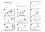
INSTALLATION
Insert Assembly
Instruction
1. Begin the insert conversion by loosening and removing the six sheet metal
screws on the rear of the unit which hold the side panels and rear panel to
the stove. These screws can be loosened using a 5/16” socket or open end
wrench.
2. Once these screws are removed, the side panels and back panel of the unit
can be removed and set aside; these panels will not be used on the insert
version of this stove.
3. Next, unlatch the two hopper lid latches near the front of the hopper lid.
Loosen and remove the hopper lid hinge retaining screws on the rear of the
unit; once these screws have been removed, the freestanding hopper lid can
be lifted off of the unit and set aside. This component will not be used on
the insert version of this stove.
4. Locate the Rear Hopper Cover Plate Assembly, which was included in the
insert conversion kit. This part comes preassembled with the rear hopper
cover plate, new hopper lid and hopper lid hinges. It also comes predrilled
for the required fasteners.
5. Lay the Rear Hopper Cover Plate Assembly on the top of the hopper lid; be
certain the assembly is centered on the stove and that all edges line up. Use
the predrilled holes as a drilling template. Without removing the hopper lid
gasket material, use a 1/8” drill bit in an electric or battery powered drill to
drill a hole at every predrilled location of the rear hopper cover plate.
• Tools Required
o Electric or battery operated drill with 1/8” drill bit.
o Socket wrench with 1/2”, 5/16” and 1/4” sockets.
• Parts Included In Insert Conversion Kit
o Surround Top Panel
o Surround Left Panel
o Surround Right Panel
o Left Side Panel
o Right Side Panel
o Rear Hopper Cover Plate Assembly

Page | 8
INSTALLATION
Insert Assembly Continued
6. Use the included self-drilling sheet metal screws to screw the Rear Hopper
Cover Plate to the hopper of the stove while carefully holding the lid in
place to be certain in remains centered on the stove. A set of clamps or an
extra set of hands is very useful at this point of the conversion, but not
required.
7. Using a 5/16” socket or open end wrench, remove one of the hopper lid
latches from the original hopper lid. Install this hopper lid latch on the new
hopper lid and check to be certain the hopper lid is closing tightly. If not,
adjust the latch until a proper seal is made.
8. Next, install the insert side panels; these panels install much the same way as
the original side panels. Do not screw the side panels to the stove using the
rear screws at this time.
9. Install the surround side panels, one side at a time, and install the two self-
tapping sheet metal screws into the pre-drilled holes in the stove body.
These screws should pass through the surround side panel, the insert side
panel and then into the stove body.
10. Next, slide the top surround panel onto the pre-installed sheet metal screws
on the top of the Rear Hopper Cover Plate. Install two ¼” bolts through the
pre-drilled holes on either side of the surround top panel where it meets the
two side panels of the surround.
11. Tighten the 1/4” bolts first, and then, using a 5/16” socket or open end
wrench, tighten the sheet metal screws on the top of the Rear Hopper Cover
Plate.
12. Using a 5/16” socket or open end wrench, remove the two sheet metal
screws which hold the control panel mounting box to the stove body. The
wires which connect the control board to the stove components have been
intentionally long, so that the control board can simply be remounted to the
right surround panel without any additional wiring.
13. Loosen the four bolts that secure the pedestal to the unit. These bolts are
located on the underside of the unit and can be loosened and removed using
a ½” socket on a socket wrench. ONCE THESE BOLTS ARE
LOOSENED AND REMOVED, THE UNIT IS FREE FROM THE
PEDESTAL AND CAN FALL, CAUSING INJURY. BE CAREFUL
WHEN REMOVING THESE BOLTS AND HAVE A HELPER WHEN
LIFTING THE STOVE FROM THE PEDESTAL.

Page | 9
INSTALLATION
Clearances to Combustibles
UnitClearancestoCombustibles
ClearancetoMantle(A) Side(B)
16IN. 6IN.
406.4MM. 152.4MM.
WARNING
• INSTALL VENT AT CLEARANCES SPECIFIED BY THE VENT
MANUFACTURER.
• HOT! Do not touch! Severe burns or clothing ignition may result.
• Glass and other surfaces are hot during operation.
CAUTION
• Keep children away.
• Supervise children in the same room as this appliance.
• Alert children and adults to the hazards of high temperatures.
• Do NOT operate with protective barriers open or removed.
• Keep clothing, furniture, draperies and other combustibles away.
• Installation MUST comply with local, regional, state and national codes and
regulations.
• Consult local building, fire officials or authorities having jurisdiction about
restrictions, installation inspection, and permits.

Page | 10
INSTALLATION
Venting Introduction
This pellet stove operates on a negative draft system, which pulls
combustion air through the burn pot and pushes the exhaust air to the vent pipe and
out of the building. This unit must be installed in accordance with the following
detailed descriptions of venting techniques; not installing the stove in accordance
with the details listed here can result in poor stove performance, property damage,
bodily injury or death. England’s Stove Works is not responsible for any damage
incurred due to a poor or unsafe installation.
If questions arise pertaining to the safe installation of the stove, our customer
service line (800-245-6489) is available. Contact your local code official to be
certain your installation meets local and national fire codes and if you’re uncertain
about how to safely install the stove, we recommend contacting a local NFI
certified installer to perform the installation.
Venting Guidelines
• ALWAYS install vent pipe in strict adherence with the instructions and
clearances included with your venting system.
• DO NOT connect this pellet stove to a chimney flue which also serves
another appliance.
• DO NOT install a flue pipe damper or any other restrictive device in the
exhaust venting system of this unit.
• ONLY use chimney liners listed for pellet appliance venting; do not use
galvanized or B-Vent pipe.
• INSTALL a block-off plate in the throat of the fireplace opening.
• SEAL each joint of pellet vent with high temperature silicone (Part # AC-
RTV3) to prevent smoke spillage into the home.
• AVOID excessive horizontal runs and elbows, as both will reduce the draft
of the venting system and will result in poor stove performance.
• INCLUDE as much vertical pipe as possible to prevent smoke from the unit
from entering your home in the event of a power outage.
• INSPECT your venting system often to be certain it is clear of fly-ash and
other restrictions.
• CLEAN your venting system as detailed in the maintenance section of this
manual.
WARNING: Venting system surfaces get HOT, and can cause burns if
touched. Noncombustible shielding or guards may be required.

Page | 11
INSTALLATION
Additional Venting Information
• The installation of a fireplace insert can be challenging and requires
knowledge of chimney systems that the average homeowner does not have.
Due to this, England’s Stove Works highly recommends having this insert
professionally installed.
• However, if this installation is performed by the homeowner, follow the
guidelines listed below:
• Do not mix and match components from different pipe manufacturers when
assembling your venting system (i.e. Do NOT use venting pipe from one
manufacturer and a termination cap from another).
• A FULL chimney relining is required when installing this stove as an insert.
o For chimneys 15 ft. or shorter, 3 in. pellet liner may be used.
o For chimneys 15 ft. or taller, 4 in. pellet liner must be used.
• For high altitude installations (altitudes greater than 4000 ft.), this insert
must be used with 4” pellet liner only. Using 3” liner will restrict air flow to
the unit at high altitudes and result in poor performance and a dirty burn.
• Outside combustion air must be connected, either by running the outside air
duct down through the ash clean-out of the fireplace, OR by running the
outside air duct to the top of the chimney. More information pertaining to
correct outside air installation can be found in the “Outside Air” section,
page 13.

Page | 12
INSTALLATION
Approved Venting Method
: Full Chimney Relining
• Use a chimney liner system specifically
designed for pellet stove use; follow the
guidelines in the previous section regarding
appropriate liner diameter.
• Use the tee supplied by the liner
manufacturer to connect the exhaust outlet
of the stove to the chimney lining system.
• Seal the throat of the fireplace with a sheet
metal block-off plate screwed to the walls
of the fireplace.
• Seal the top of the chimney opening using
the Top Plate provided by the liner
manufacturer (or, for abnormal installations,
fabricate the top plate from sheet metal).
• Use High Temp RTV silicone to seal the top
plate and prevent leaks.
• If the liner system is not a “Twist-Lock”
design, all joints should be secured with
three sheet metal screws.
• Seal all joints in the liner using High Temp
RTV silicone.
• Secure the outside air pipe to the stove using a hose clamp or other mechanical
fastener. The outside air pipe may be run to the top of the chimney system and
terminated (as shown above), or may be run down through the ash dump, in the
case of a masonry fireplace.
Please Note:
Installation diagrams are for reference purposes only and are not drawn to scale, nor
meant to be used as plans for each individual installation. Please follow all venting
system requirements and maintain the required clearances to combustibles.

Page | 13
OUTSIDE AIR HOOK-UP
• The use of outside combustion air is mandatory on the 25-EP Insert.
• The outside air connection pipe protrudes from the lower rear center of the
stove; use the included outside air kit to attach your stove to outside combustion
air. Instructions and all the parts needed to make the outside air connection to
your pellet stove are included with the outside air kit.
• Outside air can be drawn from an outside air system which terminates ath the
top of the chimney opening or down through the ash dump (if your fireplace is
so equipped.) The best choice for outside air connection is the one which uses
the shortest distance or outside air pipe.
• If it is not feasible to use the included outside air hookup kit in your stove
installation, other materials may be used provided the following rules are
followed:
o The pipe used for outside air hookup must be metal, with a minimum
thickness of .0209 in. (25 gauge mild steel) or greater and an inside
diameter of approximately 2.0in.
o All pipe joints and connections should be sealed with pipe clamps or
other mechanical means, to insure a leak free outside air connection.
o Long runs of pipe and excessive elbows for outside air should be
avoided. Due to frictional resistance in pipe, any excessive outside air
piping can result in poor stove performance.
o A screen or other protection device must be fitted over the outside air
termination point to prevent rain, debris and nuisance animals from
entering the piping system.
o Increase the outside air pipe size to 3.0 in. diameter pipe if the outside air
connection is more than 6ft. in length, more than two (2) elbows are used
or if the stove is installed in a basement.
• The outside air connection system should be inspected at least annually to be
certain it is free from blockage.
Caution
NEVER draw outside combustion air from:
• Wall, floor or ceiling cavity
• Enclosed space such as an attic, garage or crawl space.

Page | 14
FLOOR PROTECTION
• The 25-EP requires a non-combustible hearth if the current hearth of the
fireplace does not extend the required distance from the front of stove. Follow
the diagram below to determine if the current fireplace hearth is sufficient.
• If the current fireplace hearth is not large enough to accommodate this insert, a
hearth extension pad (which is designed and sold specifically for this purpose)
can be used. A hearth extension pad should be U.L. listed, or equivalent, and
must only be noncombustible. Since the majority of the radiant heat from this
unit is projected forward, the hearth extension pad only serves to keep ashes
and sparks from landing on combustible flooring near the unit. A hearth rug is
NOT an approved substitute for a proper hearth extension pad.
RequiredFloorProtectionDistanceFrom
Unit
Front(A) Side(B)
6IN. 6IN.
152.4MM. 152.4MM.

Page | 15
DAILY OPERATION
Getting Started
• Check to see that the hopper is clean and free from foreign materials. Be sure
to connect this unit to a working outlet; we recommend using a surge protector
to help protect the electronic components from damage.
• BEFORE your first fire, dry run your unit (no pellet fuel in the hopper) for
twenty minutes; pressing the “ON” button, with the unit plugged in will initiate
the dry run.
o Once the “ON” button is pressed, you should immediately hear the
exhaust blower start and operate continuously.
o After about three to five minutes, look for the red glow of the igniter in
the igniter port of the burn pot to be certain it is operating normally.
o Hold the hopper lid switch down with your finger and check to see that
the auger is turning. Release the hopper lid switch and be certain that the
auger stops turning. DO NOT PUT YOUR FINGERS IN THE
HOPPER OR NEAR THE ROTATING AUGER.
• After about twenty minutes, the control board should display “E-2” in the two
display windows (More information on Error Codes can be found in the Error
Code section of this manual).
• At this point, the dry run is complete and your pellet heating appliance is ready
for normal operation.
Lighting a Fire
• In order for this stove to operate, the hopper must first be filled with pellet fuel.
Lift the hopper lid using the flush-mount handle and pour the pellet fuel directly
into the hopper.
We recommend using only pellets manufactured by PFI Certified
facilities, since pellets bearing the PFI stamp of approval will be low
in ash and moisture, high in BTU’s, and uniform in size and quality.

Page | 16
• The 25-EP will perform equally well using softwood and hardwood pellets, and
although the ash may differ slightly in appearance or texture, both types of
pellets will burn cleanly and efficiently in this stove.
• The 25-EP is equipped with an automatic pellet ignition system; the only user
input required to light the stove is a simple press of the “On” button.
• Shortly after pressing the “On” button, the letters “S U” will appear in the heat
range and blower speed windows of the control board. This indicates the stove
has entered the start-up sequence and is operating normally.
• The fuel feed rate and combustion air during start-up is determined by the
control board, so the stove may be started on any heat range, although we
recommend starting the stove on Heat Range 5 to help ensure a strong fire is
initiated.
• After approximately fifteen minutes, the fire should be burning brightly and the
“S U” should disappear from the control board. At this point, the stove has
begun normal operation and the display windows on the control board will
remain empty unless the Heat Range or Blower Speed is adjusted.
Daily Operation Notes
• Variation in the flame height is normal, and may be particularly noticeable on
lower heat range settings. Not all wood fuel is uniform in size, which can affect
the way pellets are fed into the burnpot.
• Although the flame height may increase and decrease during operation, the
temperature of the exhaust gas remains relatively constant. Since heat is
exchanged from the exhaust gas and into the room, there is no loss of efficiency
during the periods of high and low flame.
CAUTION
NEVER USE GASOLINE, GASOLINE-TYPE LANTERN FUEL,
KEROSENE, CHARCOAL LIGHTER FLUID, OR SIMILAR LIQUIDS TO
START OR “FRESHEN UP” A FIRE IN THIS HEATER. KEEP ALL SUCH
LIQUIDS WELL AWAY FROM THE HEATER WHILE IN USE.

Page | 17
CONTROL BOARD SETTINGS
The control board on this stove allows the user to adjust the heat output and
convection blower speed, turn the unit on and off, and test components for function
(more on diagnostic mode later).
• The lower buttons on the control board (Low Fuel Feed, Low Burn Air, and Air
on Temp) are not meant to be adjusted during normal operation of the unit.
These buttons are factory preset and should not be adjusted by the user.
• To energize the unit and initiate a fire, press the “On” button. The LED above
the button should turn green and the control board should display “S U” shortly
after pressing the button.
• To shut the unit down, press the “Off” button. The LED above the button
should turn red and the board should display “S d” shortly after pressing the
button. This initiates the shut down sequence, and the stove will remain in shut
down mode until it has cooled down.
• To increase the heat output of the stove, press the “Up” heat range button. The
number in the heat range display window will increase, signifying that the
control board is now adjusting the heat output to your desired level. The blower
speed will increase the same amount as the heat range because the stove is
designed to operate with the blower speed greater than or equal to the heat
range. Pressing the “Down” arrow will decrease the heat range and blower
speed.
• To increase the blower speed without increasing the heat range, press the “Up”
arrow until the desired blower speed is shown in the display window. Pressing
the “Down” arrow will decrease the blower speed; however the control board
will not let the blower speed be set lower than the heat range.

Page | 18
ERROR CODES
Error codes or “E-Codes” are alphanumeric codes that will appear in the Heat
Range and Blower Speed windows of the Control Board if the unit experiences an
abnormal condition. Error codes are the control board’s way of telling the user that
something isn’t operating correctly within the stove and that the unit should be
carefully inspected before reigniting. See the “Trouble-Shooting Guide” on pages
35-36 for additional information on error codes.
E-0
¾ When this is displayed in the control board windows, typically when
restarting after an “E-Code” shutdown, it means there are currently no
errors and the stove will begin normal operating.
E-1
¾ This error code is not used on this stove. If it displayed in the control
board windows, please contact customer service and they will diagnose
the cause of the false code.
E-2
¾ When this code is displayed in the control board window it indicates a
failure to light. Although the stove may have ignited the pellets, the
control board did not register a high enough temperature to determine the
fire was lit. If a fire was ignited, wait for the unit to cool, clean the
burnpot and restart the unit.
E-3
¾ This error code indicates the preset maximum allowable exhaust
temperature was exceeded. Commonly referred to as “Over-Firing”, the
E-3 code means something in the stove is allowing the fire to get too hot.
E-4
¾ This code is displayed based on a drop in the exhaust temperature. This
code means the fire or “proof of flame” has been lost. It usually results
from the hopper being empty.
If an error code continues to display, if the error
code seems unexplainable, or if you have any
other questions about error codes and what they
mean, please contact Technical Support at
(800)245-6489.

Page | 19
POWER FAILURE
If the power to the unit is interrupted for approximately three minutes or
less, the unit will resume operation when power is restored according to
the following table:
Unit’s State Before Power Loss State When Power Returns
ON Start-Up
Start-Up Start-Up
Shut-Down Shut-Down
OFF OFF
¾ If the power is interrupted for more than (approximately) three
minutes, the unit will be “OFF” when power returns.
¾ IMPORTANT – Do NOT open the hopper lid or the door to
the unit during power outage. Open the closest outside door and
a window to reduce the chance of any combustion byproducts
entering the home.
¾ Wait for the power to be restored and then press the “ON”
button to restart the unit, if necessary.
Caution – Shock Hazard
• Press the “Off” button and let the appliance completely cool BEFORE
unplugging the appliance and beginning any maintenance or component
replacement.
• Risk of shock if appliance is not unplugged before service.

Page | 20
THERMOSTAT OPERATION
Thermostat Installation
1. Unplug the unit and remove the back panel of the stove.
2. Locate the thermostat connect block, labeled J18, on the rear of the control
board, near the bottom (See image below and pg. 43 of this manual for a
control board diagram). It will have a small wire “jumper” installed in it
from the factory. This jumper bypasses the thermostat and should be saved.
3. Loosen the two screws using a small slotted “jewelers” screwdriver and
remove the “jumper.”
4. Insert the two thermostat wires in place of the “jumper” and retighten the
screws.
5. Reinstall the back panel and mount the thermostat; the control board
automatically reads the thermostat and your stove is now ready for
thermostat operation.
Connect
thermostat
wires here
(J18)
/