Beyerdynamic TG 550 Vocal Set User manual

Category
Microphones
Type
User manual
TG 500
––
WIRELESS MICROPHONE SYSTEM
User Manual
TG 500 – Contents
2
1. Safety information. . . . . . . . . . . . . . . . . . . . . . . . . . . . . . . . . . . . . . . . . . . . . . . . . . . . . . . Page 3
1.1 TG 500 receiver system . . . . . . . . . . . . . . . . . . . . . . . . . . . . . . . . . . . . . . . . . . . . . Page 3
1.2 TG 500 handheld and beltpack transmitter system . . . . . . . . . . . . . . . . . . . . . . . . . . Page 4
1
.3 NiMH rechargeable batteries, alkaline batteries . . . . . . . . . . . . . . . . . . . . . . . . . . . . Page 4
1.4 Disposal . . . . . . . . . . . . . . . . . . . . . . . . . . . . . . . . . . . . . . . . . . . . . . . . . . . . . . . . Page 4
2. TG 500SR and TG 500DR diversity receiver . . . . . . . . . . . . . . . . . . . . . . . . . . . . . . . . . . . . Page 5
2.1 Positioning the receiver . . . . . . . . . . . . . . . . . . . . . . . . . . . . . . . . . . . . . . . . . . . . . Page 5
2.2 Operation and controls . . . . . . . . . . . . . . . . . . . . . . . . . . . . . . . . . . . . . . . . . . . . . . Page 5
2.3 Connecting antennas . . . . . . . . . . . . . . . . . . . . . . . . . . . . . . . . . . . . . . . . . . . . . . . Page 7
2.4 Connecting and setting up remote antennas . . . . . . . . . . . . . . . . . . . . . . . . . . . . . . . Page 9
2.5 Connecting the receiver to a microphone input . . . . . . . . . . . . . . . . . . . . . . . . . . . . . Page 9
2.6 Connecting/disconnecting the receiver to/from the mains . . . . . . . . . . . . . . . . . . . . . . Page 10
2.7 Initial operation . . . . . . . . . . . . . . . . . . . . . . . . . . . . . . . . . . . . . . . . . . . . . . . . . . . Page 10
2.7.1 Switching the receiver on/off . . . . . . . . . . . . . . . . . . . . . . . . . . . . . . . . . . . . . Page 10
2.8 Menu settings . . . . . . . . . . . . . . . . . . . . . . . . . . . . . . . . . . . . . . . . . . . . . . . . . . . . Page 11
3. TG 500H handheld transmitter . . . . . . . . . . . . . . . . . . . . . . . . . . . . . . . . . . . . . . . . . . . . . Page 19
3.1 Operation and controls . . . . . . . . . . . . . . . . . . . . . . . . . . . . . . . . . . . . . . . . . . . . . . Page 19
3.2 Inserting the batteries . . . . . . . . . . . . . . . . . . . . . . . . . . . . . . . . . . . . . . . . . . . . . . Page 19
3.3 Initial operation of the handheld transmitter . . . . . . . . . . . . . . . . . . . . . . . . . . . . . . . Page 20
3.4 Using the sensitivity switch . . . . . . . . . . . . . . . . . . . . . . . . . . . . . . . . . . . . . . . . . . . Page 21
3.5 Care instructions . . . . . . . . . . . . . . . . . . . . . . . . . . . . . . . . . . . . . . . . . . . . . . . . . . Page 22
4. TG 500B beltpack transmitter . . . . . . . . . . . . . . . . . . . . . . . . . . . . . . . . . . . . . . . . . . . . . . Page 23
4.1 Operation and controls . . . . . . . . . . . . . . . . . . . . . . . . . . . . . . . . . . . . . . . . . . . . . . Page 23
4.2 Inserting the batteries . . . . . . . . . . . . . . . . . . . . . . . . . . . . . . . . . . . . . . . . . . . . . . Page 24
4.3 Initial operation of the beltpack transmitter . . . . . . . . . . . . . . . . . . . . . . . . . . . . . . . Page 24
4.4 Using the sensitivity switch . . . . . . . . . . . . . . . . . . . . . . . . . . . . . . . . . . . . . . . . . . . Page 25
4.5 Fastening the belt clip . . . . . . . . . . . . . . . . . . . . . . . . . . . . . . . . . . . . . . . . . . . . . . Page 25
5. Synchronisation . . . . . . . . . . . . . . . . . . . . . . . . . . . . . . . . . . . . . . . . . . . . . . . . . . . . . . . . Page 26
6. Instructions for all transmitters. . . . . . . . . . . . . . . . . . . . . . . . . . . . . . . . . . . . . . . . . . . . . . Page 26
7. Components . . . . . . . . . . . . . . . . . . . . . . . . . . . . . . . . . . . . . . . . . . . . . . . . . . . . . . . . . . . Page 27
8. Sets . . . . . . . . . . . . . . . . . . . . . . . . . . . . . . . . . . . . . . . . . . . . . . . . . . . . . . . . . . . . . . . . . Page 27
9. Optional accessories . . . . . . . . . . . . . . . . . . . . . . . . . . . . . . . . . . . . . . . . . . . . . . . . . . . . . Page 28
10. Technical specifications . . . . . . . . . . . . . . . . . . . . . . . . . . . . . . . . . . . . . . . . . . . . . . . . . . . Page 29
11. Service. . . . . . . . . . . . . . . . . . . . . . . . . . . . . . . . . . . . . . . . . . . . . . . . . . . . . . . . . . . . . . . Page 30
12. Authorisation and registration obligation . . . . . . . . . . . . . . . . . . . . . . . . . . . . . . . . . . . . . . . Page 30
13. Simplified EU declaration of conformity . . . . . . . . . . . . . . . . . . . . . . . . . . . . . . . . . . . . . . . Page 30
TG 500 – Safety information
3
Thank you for putting your trust in us and choosing to buy the
beyerdynamic TG 500 wireless system. Before using it for the first
time, please take a moment to carefully read this user manual.
The system is extremely flexible and is suitable for professional
audio applications on a stage, on tour or for installations.
It has an operating range of up to 120m with the supplied anten-
nas, and its large dynamic range allows for an excellent signal-to-
noise ratio.
The system is supplemented by ergonomic handheld and beltpack
transmitters. Sophisticated battery compartment solutions allow
for rapid battery replacement.
1. Safety information
General
Please READ this user manual.
Please KEEP this user manual.
Please FOLLOW the specified operating and safety instructions.
Disclaimer
Beyerdynamic GmbH & Co. KG will not be liable for any damage
to the product or injury to persons caused by negligent,
improper, incorrect or inappropriate operation of the product.
1.1 TG 500 receiver system
1. Please read these instructions.
2. Please keep these instructions.
3. Please observe all warnings.
4. Follow all instructions.
5. Do not use this device near water.
6. Only clean the device with a dry cloth.
7. Do not mount the device near sources of heat such as
radiators, heat accumulators, ovens or other appliances
(including power amplifiers) that give off heat.
8. Do not make any changes to this device’s power plug.
9. Protect the connector cable from pinching or kinking,
especially at the appliance itself and at the power plug.
10. Only use accessories for this device that are specified by the
manufacturer.
11. Disconnect the device from the mains during thunderstorms or
if you do not intend to use it for long periods of time.
12. All maintenance work must be carried out by service personnel
that are qualified to do so. Maintenance is required if the
device itself or its power cable has been damaged, if liquids
or objects have fallen into the device, if the device has been
exposed to rain or heavy moisture, if the device is not
operating properly, or if it has been dropped
Location
The device must be set up in such a way that the power adaptor
and all connections on the rear of the device are easily
accessible.
When transporting the device to a different location, make sure
it is adequately secured and that nobody can be injured in the
event of falls or impacts.
Fire safety
Never place open fire sources (e.g. candles) on the device.
Moisture / heat sources
Never expose the device to rain or high humidity. Do not install
it in the immediate vicinity of swimming pools, shower facilities,
damp basements or other areas with unusually high air
humidity.
Never place objects filled with water (e.g. vases or drinking
glasses) on the device. Liquids in the devices may cause a short
circuit.
Never install or operate the device in the immediate vicinity of
radiators, lighting systems or other heat-generating devices.
TG 500SR connection
Lay all connector cables so that people cannot trip over them
and injure themselves.
Always remove the power adaptor from the power supply when
undertaking any work on the inputs and outputs.
The input voltage is 100–240V AC; the power consumption of
the device is approx. 3W.
If the device has caused a defective fuse or a short circuit,
disconnect it from the mains and have it checked and repaired.
Always unplug the power adaptor from the mains and/or the
device by pulling at the plug – never by pulling the cable.
Do not use the device if the power adaptor is damaged.
Connection of defective or unsuitable accessories could cause
damage to the device. Therefore, only use power adaptors that
are available from or recommended by beyerdynamic.
To disconnect the device from the mains, pull the power adaptor
out of the power socket.
TG 500DR connection
The device must be connected to a power socket with a
protective contact.
Always lay the cable so that it cannot kink or be cut through by
sharp objects.
Lay all connector cables so that people cannot trip over them
and injure themselves.
Always turn off the power supply when undertaking any work on
the inputs and outputs.
The input voltage is 100–240V AC; the power consumption of
the device is approx. 11W.
Check whether the connection ratings correspond to the existing
mains supply. Connecting the system to an incorrect power
supply may cause serious damage. Incorrect voltage may
damage the device or cause an electric shock.
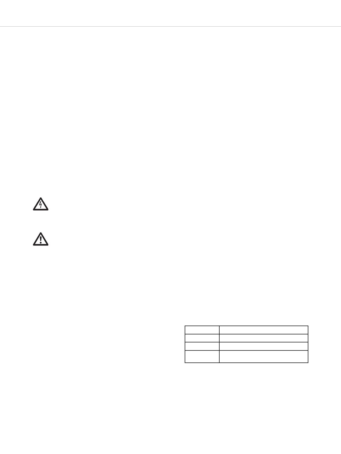
Please note that different mains voltages require corresponding
power cables and connector plugs.
Please refer to the table below:
If the device has caused a defective fuse or a short circuit,
disconnect it from the mains and have it checked and repaired.
Do not touch the power cable with wet hands. There must be no
water or dust on the contact pins. In either case, you could
suffer an electric shock.
The power cable must be securely connected. There is a risk of
fire if it is loose.
Always unplug the power cable from the mains and/or the device
by pulling at the plug never by pulling the cable. This could
damage the cable and cause an electric shock or fire.
Do not use the device if the mains plug is damaged.
The lightning symbol in an isosceles triangle
alerts the user to an uninsulated and potentially
hazardous contact voltage within the device that may
be strong enough to give users an electric shock.
An exclamation mark in an isosceles triangle alerts
the user to important instructions for operating and
maintaining the product in the accompanying
documentation.
Voltage Standard power plug
110 to 125V UL817 and CSA C 22.2 No. 42.
220 to 230V CEE 7 page VII, SR section 107-2-D1/IEC 83 page C4.
240 V BS 1363 (1984): “Specification for 13A fused plugs
and switched and un-switched socket outlets.”
TG 500 – Safety information
4
Connection of defective or unsuitable accessories could cause
damage to the device. Therefore, only use connector cables that
are available from or recommended by beyerdynamic.
To disconnect the receiver from the mains, switch it off and pull
the power plug out of the power socket.
Troubleshooting/repairs
Never open the device yourself.
Refer all service work to authorised professionals only.
Cleaning
Only clean the device with a dry or slightly damp cloth. Never
use solvents, as these will damage the surface.
1.2 TG 500 handheld and beltpack transmitter
system
Protect the transmitter from moisture, falling and impacts. You
may injure yourself or others or damage the transmitter.
Always switch the transmitter off before replacing the batteries.
Handheld transmitter
Do not blow into the microphone. In condenser microphones,
this could damage the converter. Perform a voice test instead.
Beltpack transmitter
Clip-on microphones can be very small. There is a risk of
suffocation if accidentally swallowed. Therefore, keep such
microphones out of the reach of children.
Battery care
Avoid complete draining of the battery. This could damage the
battery and shorten its service life.
If battery-powered devices are not used for long periods of
time (e.g. 1 year), battery self-discharge may be accelerated.
For long-term storage, the temperature should be between
+10°C and +30°C.
If you do not use the transmitter for several months, the
transmitter batteries should be removed and charged at least
once a year to prevent leakage or deterioration in performance
due to self-discharge
Charging contacts
The charging contacts could cause property damage, injuries
or fire damage if they come into contact with conductive
materials such as jewellery, keys or chains. This can lead to a
closed electric circuit and, therefore, to the material
overheating. To avoid this kind of unintentional electric circuit,
the charging contacts must be handled with care. This is
especially important if the transmitter is transported in a bag
or another container along with metallic objects.
From time to time, clean the battery and charging contacts of
the transmitter with a soft, lint-free cloth moistened with spirit
or alcohol. Always remove the batteries from the battery
compartment beforehand.
1.3 NiMH rechargeable batteries,
alkaline batteries
The handheld and beltpack transmitters of the TG 500 system
can only be operated with AA (LR6) Mignon alkaline batteries or
structurally identical NiMH rechargeable batteries.
Standard alkaline batteries may have length tolerances of
2–3mm. It is therefore important to ensure a good contact when
replacing the batteries.
If you do not use the transmitter for weeks or months, please
remove the batteries. Batteries may leak after long periods of
non-use and may corrode circuit paths and other components.
This means repairs will no longer be possible. In this case, all
warranty claims will be void. Even the description “Leak proof”
on batteries is not a guarantee against leaks.
Never disassemble the batteries. The contained battery acid will
damage skin and clothing.
Misuse or improper use could cause the batteries to leak. In
extreme cases, there is a risk of explosion, heat, fire, smoke or
gas.
Never expose the batteries to excessive heat such as sunshine,
fire or the like.
1.4 Disposal
Remove the batteries when disposing of the transmitter.
Used batteries may contain harmful substances that are harmful
to your health and the environment.
Always dispose of used batteries in accordance with the
applicable disposal regulations. Do not throw batteries into fire
(risk of explosion) or into residual waste. Please hand in
batteries at retail outlets or at communal recycling centres.
Return is free of charge and stipulated by law. Please only
dispose of discharged batteries in the containers provided.
Details of how to remove batteries from the device can be found
in the chapter “Inserting the batteries”.
All batteries get recycled. This allows for valuable raw materials
such as iron, zinc or nickel to be regained.
At the end of its operating life this product may not
be disposed of along with normal household waste.
Please take it to a designated recycling point for
electric and electronic appliances. This is indicated
by the symbol on the product, the operating
instructions or the packaging
TG 500 – Diversity receiver
5
2. TG 500SR and TG 500DR diversity receiver
2.1 Positioning the receiver
Position the receiver in the room in which the transmission is taking place.
Position the receiver as close as possible to the transmitter. For optimum reception, there should be a line of sight between the trans-
mitter and the receiver. The minimum distance between the transmitter and receiver is 1m.
Do not position the receiver directly next to digitally controlled devices.
2.2 Operation and controls


Figure 2-1: TG 500SR single-channel receiver – front
On/off button
Infrared interface for synchronisation of receiver and
transmitter
Backlit LCD
Up button
Down button
Enter button
Exit button
Button for synchronisation of receiver and transmitter

Figure 2-2: TG 500DR two-channel receiver – front

TG 500 – Diversity receiver
6
Figure 2-3: TG 500SR receiver – back
Figure 2-5: TG 500SR/DR receiver display
Overload display
Active diversity channel A or B
HF level display
Audio level display
Transmitter battery display
Transmitter mute function activated
Transmitter lock function activated
Text display
Figure 2-4: TG 500DR receiver – back
Antenna input A or B
Information about frequency band
Audio output, 3-pin jack
Audio output, 3-pin XLR
TG 500SR: DC connector for power adaptor, 12V DC, 500mATG
500DR: Mains connection 100–240V, 50/60Hz, max. 15W
Strain relief for the power adaptor cable
M
TG 500 – Diversity receiver
7
Figure 2-6: Connecting antennas
Figure 2-7: Positioning of antennas
Mounting the Rack Mount Kit on a TG 500SR receiver
Attach the shorter mounting bracket to one side of the
receiver with the three supplied M4 screws.
Attach the longer mounting bracket to the other side of the
receiver with the three supplied M4 screws.
Figure 2-8: Mounting the Rack Mount Kit to a receiver, top-down
view
Figure 2-9: Mounting the Rack Mount Kit to a receiver, front view
Mounting the Rack Mount Kit to two TG 500SR single-channel
receivers or a TG 500DR two-channel receiver
Connect the underside of two TG 500SR receivers to a panel
with four supplied M4 screws.
Attach one mounting bracket to the right and one to the left of
the two connected TG 500SR single-channel receivers or one
TG 500DR two-channel receiver, each with three M4 screws. .
Figure 2-10: Mounting the Rack Mount Kit to two receivers,
bottom view
Figure 2-11: Mounting the Rack Mount Kit to two receivers, front
view
2.3 Connecting antennas
Connect the supplied antennas to the antenna inputs A and B
and orient them outwards in a V shape (approx. 60° angle).
Important: For diversity operation, it is essential to connect both
antennas! Evaluation electronics select the antenna that
provides the best signal.
If the receiver is to be built into a 19” rack, the antennas can
be attached to the front of the receiver. To do this, use the
supplied Rack Mount Kit and the optionally available WA-CKF
antenna front mounting kit.
TG 500 – Diversity receiver
8
Connect the antenna cables of the antenna front mounting kit
to the antenna inputs A and B .
Loosen the nuts and washers of the enclosed adaptors.
Push the adaptors through the respective opening, with the
thread of the adaptor facing the front.
Attach each of the adaptors with the washer and nuts.
Push the receiver into the 19” rack and screw it to the rack with
four suitable screws (not included).
Connect each of the antenna cables to the back of the adaptor.
Connect each of the antennas to the front (BNC sockets) of the
adaptor.
Position the antennas in a V shape facing outwards.
Caution!
When installing the receiver in a 19 rack or together with
multiple devices in a rack, the ambient temperature, the
mechanical load and the electrical potential may behave
differently than in individual devices.
If you mount more than one receiver in a rack, one rack unit
should always be kept free or suitable ventilation should be
ensured, e.g. through ventilation panels, due to the heat build-
up between the receivers.
The ambient temperature in the rack must not exceed the
temperature specified in the technical specifications.
Make sure the rack does not become top-heavy due to too many
devices so that it could fall over.
When connecting to the mains, please note the information on
the name plate. Avoid overloading the electric circuits. Provide
overcurrent protection if necessary.
Figure 2-12: Antenna front mounting
Figure 2-13: Positioning of antennas
TG 500 – Diversity receiver
9
2.4 Connecting and setting up remote antennas
If the reception in the location of the receiver is not optimal, we
recommend using remote antennas.
TG 500SR
As the TG 500SR receiver does not provide a power supply, only
the WA-ATO antennas (optionally available) or the WA-AMP2
antennas with additional power supply can be used. If there is
more than one TG 500SR, we recommend using a splitter that
provides the power supply.
TG 500DR
As the TG 500DR receiver has a short-circuit-proof voltage of
8V DC at both antenna inputs with a maximum load of 150mA
available for power supply, active antennas such as the WA-ATDA
(optionally available) can also be used.
If the length of the antenna cable is greater than 10m, an antenna
amplifier (WA-AMP2) or an active antenna is required to
compensate for the attenuation loss arising in the cable.
1. Connect the reception antennas to the antenna inputs A
and B and position the antennas to the right and left of the
active area in which the transmitter is to be used. Changing
the positioning of the reception antennas may improve
reception.
2. A minimum distance of 1m should be maintained between the
reception antennas; the maximum distance between the two
reception antennas should not exceed 5m.
3. The distance between the transmitter and reception antenna
should be at least 1.5m to avoid overloading and thus
interference between the different channels. If this distance
cannot be maintained, we recommended positioning the
reception antennas raised, especially for multi-channel
systems.
Important:
1. Install the reception antenna in the room where the
transmission is to take place.
2. To avoid interference, do not position the reception antennas
next to digitally controlled devices or attach to lighting masts
(hum interference).
3. Keep a minimum distance of 50cm from metal objects,
including reinforced concrete walls.
4. Do not bend antenna cables too much; keep them in arch
shapes instead. Mechanically protect the antenna cable from
pulling if necessary.
Figure 2-14: Connecting remote antennas TG 500SR
Figure 2-14a: Connecting remote antennas TG 500DR
2.5 Connecting the receiver to a microphone input
The receiver has balanced audio outputs.
Connect the balanced XLR or jack output to the balanced
microphone input on the mixing console or amplifier.
In the menu settings of the relevant channel, adjust the level of
the audio output to the input level of the amplifier or the mixing
console. See chapter 2.8 “Menu settings”.
Figure 2-15: Receiver audio outputs
TG 500 – Diversity receiver
10
2.7 Initial operation
2.7.1 Switching the receiver on/off
After you have mounted and connected the receiver, switch it on
at the on/off button .
After switching on the receiver without a transmitter switched on
at the same frequency, the display shows the following by
default:
The currently set name (e.g. name of the performer)
The currently set frequency or group and channel
Once you have turned on a TG 500 transmitter at the same
frequency or synchronised it with the receiver, you can read off
the audio and HF level on the display from the bar charts.
Note:
If the HF level is displayed even though there is no transmitter
switched on, there may be interference/faults caused by another
transmitter at the same frequency. In this case, you should
select a different frequency on the receiver and then
synchronise your transmitter. You can set a suitable frequency
with the scan function. See chapter 2.8 “Menu settings”,
“Scan” section.
The receiver has a receiver unit for the antennas A and B. It
automatically switches to and transmits the strongest signal
received. The currently active diversity channel (A or B) is
shown on the display.
A battery symbol displays the battery status of the switched-
on transmitter. Six bars in the battery symbol indicate full
batteries. If no more bars are shown, or if the battery symbol is
flashing, the batteries only have an operating time of approx.
10 to 30 minutes remaining. In this case, you should replace
the batteries in the transmitter as soon as possible.
Figure 2-19: Display screen with a valid
transmitter signal available
Figure 2-18: Display screen without
a valid transmitter signal available

2.6 Connecting/disconnecting the receiver to/from
the mains
Check whether the mains voltage indicated on the receiver
corresponds to the mains voltage at the operation site
Caution: Operating the device at a different mains voltage may
lead to irreparable damage to the device
TG 500SR:
Connect the power adaptor to the DC connector and a power
socket.
TG 500DR:
Connect the power cable to the mains connection and a
power socket.
To disconnect the receiver from the mains, pull TG 500SR the
plug out of the DC connector and the power adaptor out of
the power socket or, on the TG 500DR, pull the power cable
out of the power socket.
user
794.000
user
800.000
user
794.000

Figure 2-16: TG 500SR receiver mains connection
TG 500SR
TG 500DR
Figure 2-17: Receiver on/off
TG 500 – Diversity receiver
11
2.8 Menu settings
You can change the settings for the name, frequency group, frequency, gain, etc. in the various menus on the receiver.
Press the enter button to open the menu.
Press the down or up button to scroll through the menu.
Press the enter button to open the various submenus and, once the parameter starts flashing, you can change the settings using the
up or down buttons .
Press the enter button to confirm the selected setting.
You can exit the menu or menu item at any time with the exit button . Caution: if you exit the menu while changing a setting, it will be
discarded.
We recommend changing all the settings on the receiver first, and then switching on and synchronising the transmitter so that it takes
over all the settings. The settings described in this chapter are changed without the transmitter switched on.
Caution: If you do not change any settings or press the enter button for a few seconds, the submenu will close automatically and the
standard view will reappear on the display . Settings that are not confirmed by pressing the enter button will not be saved.
user
794.000

The following menu settings are possible:
NAME
In the “NAME” menu, you can enter a name, e.g. the name of the performer.
Press the enter button to open the submenu.
Press the up or down button to select the letters/characters. You can enter a
maximum of seven letters/characters.
Press the enter button to confirm.
Figure 2-21: Selecting the “Name” menu
name
user
Figure 2-22: Entering a name
user
"
"
"
"
Figure 2-20: Receiver switched on / transmitter off
Figure 2-20a: Receiver switched on / transmitter off
TG 500 – Diversity receiver
12
Frequency group (GR) / Channel (CH)
In the “GR/CH” menu, you can select a predefined (intermodulation-free) frequency
group and a channel from this group.
Press the enter button to open the submenu.
Press the up or down button to select the desired group. Depending on the
frequency band, you can select from up to 8 groups. In each group, the channels are
arranged in irregular frequency intervals. This means that interference between the
transmitters is largely avoided.
Press the enter button to confirm.
Note: for multi-channel systems, the frequencies must be within one group.
Press the enter button to so that you can select the desired channel from the
previously selected group. Press the up or down button to select the channel.
Press the enter button to confirm.
M
a
n
u
a
l
f
r
e
q
u
e
n
c
y
I
n
t
h
e
F
R
E
Q
M
A
N
m
e
n
u
,
y
o
u
c
a
n
m
a
n
u
a
l
l
y
s
e
l
e
c
t
a
n
y
f
r
e
q
u
e
n
c
y
f
r
o
m
a
c
o
r
r
e
s
p
o
n
d
i
n
g
f
r
e
q
u
e
n
c
y
b
a
n
d
i
n
2
5
k
H
z
i
n
c
r
e
m
e
n
t
s
,
r
e
g
a
r
d
l
e
s
s
o
f
w
h
e
t
h
e
r
i
t
i
s
s
t
o
r
e
d
i
n
a
g
r
o
u
p
.
P
r
e
s
s
t
h
e
e
n
t
e
r
b
u
t
t
o
n
t
o
o
p
e
n
t
h
e
s
u
b
m
e
n
u
.
P
r
e
s
s
t
h
e
u
p
o
r
d
o
w
n
b
u
t
t
o
n
t
o
s
e
l
e
c
t
t
h
e
f
i
r
s
t
t
h
r
e
e
f
i
g
u
r
e
s
o
f
t
h
e
d
e
s
i
r
e
d
f
r
e
q
u
e
n
c
y
.
P
r
e
s
s
t
h
e
e
n
t
e
r
b
u
t
t
o
n
t
o
c
o
n
f
i
r
m
.
P
r
e
s
s
t
h
e
u
p
o
r
d
o
w
n
b
u
t
t
o
n
t
o
s
e
l
e
c
t
t
h
e
l
a
s
t
t
h
r
e
e
f
i
g
u
r
e
s
o
f
t
h
e
d
e
s
i
r
e
d
f
r
e
q
u
e
n
c
y
.
P
r
e
s
s
t
h
e
e
n
t
e
r
b
u
t
t
o
n
t
o
c
o
n
f
i
r
m
.
Figure 2-23: Selecting the “Frequency group (GR) /
Channel (CH)” submenu
gr/ch
--/--
Figure 2-24: Selecting the frequency group (GR)
gr/ch
01/01
"
"
"
"
Figure 2-25: Selecting the channel (CH)
gr/ch
01/01
"
"
"
"
Figure 2-26: Selecting the “Frequency” submenu
freq man
794.000
Figure 2-27: Selecting the frequency first three
figures
freq man
794.000
"
"
"
"
Figure 2-28: Selecting the frequency last three
figures
freq man
800.000
"
"
"
"
TG 500 – Diversity receiver
13
SCAN
In the “SCAN” menu, you can select a channel or a frequency
from a predefined group in accordance with the particular
frequency band.
Press the enter button to open the submenu.
Press the up or down button to select the frequency group
in which to search for a suitable channel.
Press the enter button to confirm.
Press the up or down button to search for a channel from
the previously selected group from which to start the search.
Press the enter button to confirm.
The scan process will be performed. The display shows the
message “Scanning”.
The scan process is completed once the message “Scan done
OK” appears.
After completing the scan, the next free channel is
automatically selected. The selected channel and the group are
displayed.
Important: After each scan, you will need to resynchronise the
transmitter. See also chapter 5. “Synchronisation”.
Figure 2-29: Selecting the “Scan” submenu
scan
Figure 2-30: Selecting a group in which to search for
a
channel
scan at
gr 01/01
F
igure 2-31: Selecting a channel from which to start
the search
scan at
ch 01/01
"
"
"
"
Figure 2-33: Scan process completed
scan
done ok
Figure 2-35: No free channels available in the selected
group
scan
ALL BUSY
Figure 2-34: Display of the selected next free channel
after the search
user
01/04
"
"
"
"
Figure 2-32: Scan process
scanning
--------
Note: if the receiver does not find any free channels in the
selected group, the message “Scan all busy” will appear on the
display. In this case, select another group and restart the scan
process.
If no free channels are found in another group either, select the
frequency manually. We recommend switching the transmitter
off during a manual frequency selection and watching the HF
indicator on the receiver display to see if an HF level is
displayed. If an HF level is displayed even though the
transmitter is switched off, this means there are interferences
and you should select another frequency.
TG 500 – Diversity receiver
14
Gain
In the “GAIN” menu, you can adjust the receiver output level to
the input level of the amplifier or mixing console. In other
words, if the signal received through the transmitter is very
quiet, it can be amplified using the “Gain” menu item.
Press the enter button to open the submenu.
Press the up or down button to set the amplification in
3 dB increments between -12 dB and +6 dB.
Press the enter button to confirm.
For the handheld transmitter, you can adjust the sensitivity to
0/+12 dB with the two-stage gain switch :
For the beltpack transmitter, you can adjust the sensitivity to
0/+12/+24 dB with the three-stage gain switch :
passive instruments = 0 dB; active instruments = -12 dB
See also chapter 4.4 “Using the sensitivity switch”.
F
igure 2-36: Selecting the “Gain” submenu
gain
0 B
Figure 2-37: Setting the amplification for the signal
r
eceived through the transmitter
P
gain
+6 B
P
"
"
"
"
TX RF Power
In the “TX RF PW” menu, you can set the transmission power.
The “Standard” setting is recommended if the transmitter is
located near the reception antennas or for multi-channel
systems, to prevent interference from intermodulation.
The “High” setting is recommended if there are problems with
the operating range or if there is a very large distance between
the transmitter and the reception antennas.
Press the enter button to open the submenu.
Press the up or down button to set the transmission to
“High” or “Standard”.
Press the enter button to confirm.
Important: Once you have confirmed the selected option, you
will need to resynchronise the transmitter. See also chapter 5.
“Synchronisation”.
Figure 2-38: Select the “TX RF PW” submenu
TX RF PW
standard
Figure 2-39: Select the transmission power
TX RF PW
high
"
"
"
"
Figure 2-40: Selecting the “TX battery” submenu
TX batt
alkaline
Figure 2-41: Selecting alkaline battery or NiMH
rechargeable battery
TX batt
nimh
"
"
"
"
TX Battery
In the “TX BATT” menu, you can set whether an alkaline battery
or NiMH rechargeable battery is inserted in the transmitter so
that the battery or charge status is shown correctly on the
display.
Press the enter button to open the submenu.
Press the up or down button to select “Alkaline or
“NiMH” for the battery inserted in the transmitter.
Press the enter button to confirm.
Important: Once you have confirmed the selected option, you
will need to resynchronise the transmitter. See also chapter 5.
“Synchronisation”.
TG 500 – Diversity receiver
15
TX Lock
In the “TX LOCK” menu, you can set whether the transmitter
can be switched off at its on/off switch or if it is protected from
switching off by mistake. The lock symbol will appear on the
standard display:
To switch off the transmitter when the “Tx Lock” function is
activated, the following steps must be taken:
Hold the on/off button until the message “Tx PWLOCK
appears on the transmitter display.
Release the on/off button briefly.
Press the on/off button again until the message “Off
appears on the transmitter display.
Press the enter button to open the submenu.
Press the up or down button to switch the Tx Lock
function on or off.
Press the enter button to confirm. The lock symbol will be
shown on the display.
Important: once you have confirmed the selected option, you
will need to resynchronise the transmitter. See also chapter
5. “Synchronisation”.
Figure 2-42: Selecting the “TX Lock” submenu
TX lock
off
Figure 2-43: Switching on the lock function
TX lock
on
"
"
"
"
Figure 2-45: Selecting the “TX Mute” submenu
TX mute
off
Figure 2-46: Switching on the mute function
TX mute
on
"
"
"
"
Figure 2-47: Mute function activated
M
user
800.000
Figure 2-48: Microphone muted
M
Tx mute
800.000
TX Mute Mode
In the “TX MUTE” menu, you can set whether the mute button
on the transmitter is active or not.
If the “Tx Mute” function is activated (ON), the transmitter can
be muted using the on/off button (beltpack transmitter) or the
mute button (handheld transmitter).
If the “Tx Mute” function is activated, the mute symbol will
appear on the standard display:
If the “Tx Mute” function is to be deactivated so that the
transmitter is not muted using the on/off button or mute button,
select “Off”.
Press the enter button to open the submenu.
Press the up or down button to switch the Tx Mute
function on or off.
Press the enter button to confirm. The mute symbol will be
shown on the display.
Important: once you have confirmed the selected option, you
will need to resynchronise the transmitter. See also chapter
5. “Synchronisation”.
If the microphone on the transmitter is muted, this is also
indicated on the receiver display by the “TX Mute” indicator
and the name entered on the receiver alternating on the receiver
display.
M
Figure 2-44: Lock function activated
user
800.000
TG 500 – Diversity receiver
16
Audiomix – ONLY ON TG 500DR!
If you wish to emit both audio signals (e.g. vocals and guitar),
mixed across both outputs, set the Audiomix” function to
“ON”.
In the “Gain” menu, you can adjust the volume for each channel
accordingly until you achieve the desired mix.
To use both channels independently of each other, set the
“Audiomix” function to “OFF”.
Press the enter button to open the submenu.
Press the up or down button to activate (ON) or deactivate
(OFF) the “Audiomix” function. Press the enter button to
confirm.
Figure 2-49: Selecting the “Audiomix” submenu
AudiomiX
oFF
Figure 2-50: Activating/deactivating the Audiomix
AudiomiX
oN
Squelch
In the “SQUELCH” menu you can manually select the value for
the so-called squelch. The squelch is used to specify the RF
level from which the receiver is muted. This ensures that noises
are emitted as long as the transmitter is switched off or when
the transmitter is moved out of the receiving area. The default
setting is -94 dBm.
Please note the following:
If you set a higher value (up to -80 dBm), it can prevent loud
noise during use in environments with severe interference.
However, this reduces the range.
If you set a lower value (up to -100 dBm), the range is
increased, but there may be noise due to interference in the
limit range.
Press the enter button to open the submenu.
Press the up or down button to select the threshold for the
squelch between -80 und -110 dBm.
Press the enter button to confirm.
F
igure 2-51: Selecting the “Squelch” submenu
squelch
-93 b
m
P
Figure 2-52: Setting the squelch
mute at
-93 b
m
P
"
"
"
"
TG 500 – Diversity receiver
17
Restoring factory settings
In the “Factory reset” menu, you can reset the receiver to the
factory settings.
Press the enter button to open the submenu.
Press the up or down button , uto select whether you want
to restore the factory settings (”Yes”) or not (“No”).
Press the enter button to confirm.
Once you have decided to restore the factory settings, i.e.
selected Yes” and confirmed, the device will go through a
restore operation.
Restoring the factory settings is indicated by the message
“Reset”.
Once the restore operation has completed, the message “Done”
will appear.
The receiver then restarts automatically and the factory settings
will be restored.
Figure 2-53: Selecting the “Factory reset” submenu
Figure 2-54: Restore factory settings: no
factory
reset
restore
no
"
"
"
"
Figure 2-55: Restore factory settings: yes
restore
yes
"
"
"
"
Figure 2-56: Settings are being restored to factory
settings
reset
-----
Figure 2-57: Restore operation completed
done
TG 500 – Diversity receiver
18
Display system info
In the “System info” menu, you can display information about
the receiver and the system.
Press the enter button to open the submenu.
By repeatedly pressing the up or down button , you can
scroll through the submenu and display the information listed
below.
Display receiver/system hardware version
Display receiver/system hardware type
Display region band (for frequency ranges see chapter 10
“Technical specifications”)
Display current software or firmware version
To exit the “System info” submenu, press the “Exit” button .
Figure 2-58: Selecting the “System info” submenu
system
info
F
igure 2-59: Displaying hardware version
hardware
ver 1
Figure 2-60: Displaying hardware type
hardware
single
Figure 2-61: Displaying region and band
region
band 3
Figure 2-62: Displaying software or firmware version
software
rev 1.0
TG 500 – Handheld transmitter
19
3. TG 500H handheld transmitter
3.1 Operation and controls
On/off button, lit
Charging contacts
Antenna
Colour ring, interchangeable
Battery compartment cover
Programmable mute button
LCD
Microphone head (fixed)
Battery compartment
Two-stage sensitivity switch (gain) 0 dB and 12 dB
Infrared interface for synchronisation
Battery indicator
Mute function activated
Lock function activated
Text display
3.2 Inserting the batteries
Unscrew the battery compartment cover in the direction
indicated by the arrow..
Remove the battery compartment cover .
Insert two alkaline AA 1.5V batteries or NiMH rechargeable
batteries in the battery compartment according to the
symbols.
Push the battery compartment cover back up and tighten it.
1.0.0.0.0.0.0.1.X.x.x.x.x.x.1.5.5.5.5.5.5.1.i.i.i.i.i.i.
Figure 3-1: Transmitter base Figure 3-2: Front view
Figure 3-3: Battery compartment
Figure 3-4: TG 500H transmitter display
Figure 3-5: Unscrewing the
battery compartment
Figure 3-6: Inserting the batteries
TG 500 – Handheld transmitter
20
3.3 Initial operation of the handheld transmitter
Switch the handheld transmitter on by pressing and holding the
on/off button until the standard display appears on the
transmitter display . The on/off button lights up green.
The transmitter display shows the battery status as well as
the name entered on the receiver.
You can access further display functions such as frequency and
transmission power by repeatedly pressing the on/off button
or the mute button if the mute function on the receiver is not
activated.
Ensure the transmitter and receiver are working at the same
frequency.
If you hold down the on/off button when switching on, you
can display the version, hardware type, band and firmware
version.
To switch off the transmitter, press and hold the on/off button ,
until the message “Off” is displayed.
The current battery status is shown on the display on the
transmitter and the receiver . Please ensure the correct
battery type is selected in the channel menu on the receiver and
that synchronisation is carried out.
Flat batteries are indicated by an empty, flashing battery symbol
on the transmitter and receiver display. The on/off button on
the transmitter base also lights up red. In this case, you should
replace the batteries with new ones as soon as possible.
If you are using NiMH rechargeable batteries for operation, you
can charge these with the optionally available WA-CD battery
charger. The batteries can remain in the transmitter during the
charging process. Further information can be found in the
separate “WA-CD” user manual.
Important: from time to time, clean the battery and charging
contacts of the transmitter with a soft, lint-free cloth moistened
with spirit or alcohol. Always remove the batteries from the
battery compartment beforehand.
user
794.000
pw
std
band 3
rev 1.0
hw hh1
ver
F
i
gu
re 3-7: H
an
d
h
el
d
tran
sm
i
tter
F
i
gu
re 3-8:
Tr
a
ns
mit
t
e
r
dis
pla
y
S
t
a
nda
r
d
dis
pla
y
Figure 3-9:
Displaying frequency
Figure 3-10:
Displaying transmission power
Figure 3-11:
Displaying version
Figure 3-12:
Displaying hardware type
Figure 3-13:
Displaying band
Figure 3-14:
Displaying firmware version
off
Figure 3-15:
Switching off transmitter
  • Page 1 1
  • Page 2 2
  • Page 3 3
  • Page 4 4
  • Page 5 5
  • Page 6 6
  • Page 7 7
  • Page 8 8
  • Page 9 9
  • Page 10 10
  • Page 11 11
  • Page 12 12
  • Page 13 13
  • Page 14 14
  • Page 15 15
  • Page 16 16
  • Page 17 17
  • Page 18 18
  • Page 19 19
  • Page 20 20
  • Page 21 21
  • Page 22 22
  • Page 23 23
  • Page 24 24
  • Page 25 25
  • Page 26 26
  • Page 27 27
  • Page 28 28
  • Page 29 29
  • Page 30 30
  • Page 31 31

Beyerdynamic TG 550 Vocal Set User manual

Category
Microphones
Type
User manual

Ask a question and I''ll find the answer in the document

Finding information in a document is now easier with AI