Page is loading ...

NuDAQ
ACL-8216
16-bit High Resolution
Data Acquisition Card
User’s Guide

@Copyright 1996~2000 ADLINK Technolgoy Inc.
All Rights Reserved.
Manual Rev. 4.10: April 15, 2000
The information in this document is subject to change without prior
notice in order to improve reliability, design and function and does
not represent a commitment on the part of the manufacturer.
In no event will the manufacturer be liable for direct, indirect, special,
incidental, or consequential damages arising out of the use or
inability to use the product or documentation, even if advised of the
possibility of such damages.
This document contains proprietary information protected by
copyright. All rights are reserved. No part of this manual may be
reproduced by any mechanical, electronic, or other means in any
form without prior written permission of the manufacturer.
Trademarks
NuDAQ, ACL-8216 are registered trademarks of ADLINK Technology
Inc.,
Other product names mentioned herein are used for identification
purposes only and may be trademarks and/or registered trademarks
of their respective companies.


Contens
•
i
Table of Contents
How to Use This Guide.............................................iii
Chapter 1 Introduction .............................................1
1.1
Features..............................................................................2
1.2
Specifications.....................................................................2
1.4
Software Support................................................................4
Chapter 2 Installation...............................................5
2.1
What You Have ...................................................................5
2.2
Unpacking...........................................................................5
2.3
ACL-8216's Layout...............................................................6
2.4
Jumper and DIP Switch Description ...................................8
2.5
Base Address Setting..........................................................8
2.6
Analog Input Channel Configuration ................................11
2.7
DMA Channel Setting........................................................11
2.8
Internal/External Trigger Setting......................................12
2.9
Clock Source Setting........................................................13
2.10
IRQ Level Setting..............................................................14
2.11
D/A Reference Voltage Setting.........................................14
2.12
Connectors Pin Assignment..............................................16
2.13
Daughter Board Connection .............................................18
Chapter 3 Registers Format...................................21
3.1
I/O Port Address................................................................21
3.2
A/D Data Registers & Status Control Register....................22
3.3
A/D Channel Multiplexer Register.....................................23
3.4
A/D Range Control Register..............................................24
3.5
A/D Operation Mode Control Register...............................25
3.6
Clear Interrupt Register....................................................26
3.7
Software Trigger Register.................................................26
3.8
Digital I/O register.............................................................26
3.9
D/A Output Register..........................................................28
3.10
Internal Timer/Counter Register.......................................28
Chapter 4 Operation Theorem................................29
4.1
A/D Conversion.................................................................29
4.2
D/A Conversion................................................................32

ii
•
Contens
4.3
Digital Input and Output....................................................33
4.4
Timer/Counter Operation..................................................33
Chapter 5 C/C++ Library..........................................39
5.1
Installation........................................................................39
5.2
_8216_Initial......................................................................40
5.3
_8216_Switch_Card_No.....................................................41
5.4
_8216_DI............................................................................42
5.5
_8216_DI _Channel............................................................42
5.6
_8216_DO..........................................................................43
5.7
_8216_DA ..........................................................................44
5.8
_8216_AD_Input_Mode ......................................................46
5.9
_8216_AD_Set_Channel ....................................................47
5.10
_8216_AD_Set_Range .......................................................49
5.11
_8216_AD_Set_Mode.........................................................50
5.12
_8216_AD_Soft_Trig ..........................................................52
5.13
_8216_AD_Acquire ...........................................................53
5.14
_8216_CLR_IRQ.................................................................54
5.15
_8216_AD_DMA_Start........................................................54
5.16
_8216_AD_DMA_Status......................................................57
5.17
_8216_AD_DMA_Stop ........................................................57
5.18
_8216_AD_INT_Start..........................................................59
5.19
_8216_AD_INT_Status........................................................60
5.20
_8216_AD_INT_Stop ..........................................................60
5.21
_8216_AD_Timer...............................................................61
5.22
_8216_Timer_Start ............................................................62
5.23
_8216_Timer_Read............................................................62
5.24
_8216_Timer_Stop.............................................................63
Chapter 6 Calibration & Utilities............................65
6.1
What do you need............................................................65
6.2
VR Assignment..................................................................65
6.3
A/D Adjustment.................................................................66
6.4
D/A Adjustment.................................................................66
Appendix A Demo Programs...................................69
Product Warranty/Service........................................71

How to Use This Guide
•
iii
How to Use This Guide
This manual is designed to help you use the ACL-8216. The manual
describes how to modify various settings on the ACL-8216 card to meet
your requirements. It is divided into six chapters:
•
Chapter 1, "Introduction," gives an overview of the product features,
applications, and specifications.
•
Chapter 2, "Installation," describes how to install the ACL-8216. The layout of
ACL-8216 is shown, the switch setting for base address, and jumper
setting for analog input channel configuration, reference voltage
setting, trigger source, interrupt level and DMA channel are specified.
The connectors' pin assignment and how to connect the outside
signal are described.
•
Chapter 3, "Registers format," describes the details of register format and
structure of the ACL-8216, this information is very important for the
programmers who want to control the hardware by low-level
programming.
•
Chapter 4, "Operation Theorem" describes how to operate the ACL-8216. The
A/D, D/A, DIO and timer/counter functions are introduced. Also, some
programming concepts are specified.
•
Chapter 5, "C/C++ Library," describes the C++ Library for DOS environment.
•
Chapter 6, "Calibration and utilities," describes how to calibrate the ACL-8216
for accurate measurement.


Introduction
•
1
1
Introduction
The ACL-8216 is a high performance, high resolution multi-function
data acquisition card for the IBM PC or compatible computers.
CH 0
CH 1
CH 2
.
.
.
ANALOG
INPUT
>
16 BIT
DIGITAL INPUT
REGISTER
D/I 0
DI 1
DO 15
D/O 0
DO 1
DI 15
DMA SELECT
#1 OR #3
TRIG
LOGIC
PACER
TRIG
SOFTWARE
TRIG
EXTERNAL
TRIG
CH 15
D/A 1 OUT
GND
REF 1 IN
D/A 0 OUT
GND
REF 0 IN
4 MHz
OSC.
FR/2
2MHz
OUT 0
16 BIT
COUNTER #0
16 BIT
COUNTER #1
16 BIT
COUNTER #2
TO PACER TRIG
16 BIT
DIGITAL INPUT
REGISTER
12-Bit
Code Latch
16 channel
Single-ended
Analog
Multiplexer
AMP
DC/DC
CONVERTER
+15
-15
+5V
MUX SCAN
CONTROL
12-Bit
Code Latch
D/A #1 12 BIT
MULITIPLYING D/A
DATA
BUFFER
INTERRUPT
IRQ SELECT
CONTROL
LOGIC
DACK
I/O PORT DECODER
INTERNAL BUSGAIN
SELECT
D/A #0 12 BIT
MULITIPLYING D/A
16 Bit
A/D Converter
(ADS7805)
INPUT
BUFFER
>
>
<
<
EXT.CLK<
PC/AT BUS
EOC
DRQ
.
.
.
.
.
.
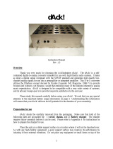
Figure 1.1 ACL -8216 BLOCK DIAGRAM

2
•
Introduction
The ACL-8216 series is designed to combine all the data acquisition
functions, such as A/D, D/A, DIO, and timer/counter in a single board,
The high-end specifications of the card makes it ideal for wide range
of applications requiring high resolution 16-bit data acquisition at
low cost. The Figure 1.1 shows the block diagram of the ACL-8216.
The ACL-8216 Series features 16 single-ended inputs or 8
differential inputs at up to 100 Khz, 2 channels multiplying 12-bit
double-buffered analog output, 16 digital inputs and 16 digital
outputs, and one timer/counter channel.
1.1 Features
The ACL-8216 High Resolution Multi-function Data Acquisition Card
provides the following advanced features:
•
AT-Bus
•
16-bit hgih resolution analog input
•
16 single-ended or 8 differential analog input channels
•
Bipolar input signals
•
Programmable gain of x1, x2, x4, x8
•
On-chip sample & hold
•
Two 12-bit monolithic multiplying analog output channels
•
16 digital output channels
•
16 digital input channels
•
3 independent programmable 16-bit down counters
•
Programmable sampling rate of up to 100KHz
•
Three A/D trigger modes: software trigger, programmable pacer
trigger, and external pulse trigger.
•
AT interrupt IRQ capability: 9 IRQ levels (IRQ3~IRQ15) are jumper
selectable.
•
Integral DC-to-DC converter for stable analog power source
•
37-pin D-type connector
•
Compact size: half-size PCB
1.2 Specifications
♦
Analog Input (A/D)
•
Converter: ADS7805 or equivalent, successive approximation type
•
Resolution: 16-bit

Introduction
•
3
•
Number of channels: 16 single-ended or 8 differential
•
Input Range: (programmable)
Bipolar :
±
10V,
±
5V,
±
2.5V,
±
1.25V
•
Conversion Time: 8
µ
sec
•
Sampling Rate:
100KHz maximum for single channe
20KHz maximum for multi-channels multiplexing
•
Overvoltage protection: Continuous
±
35V maximum
•
Differential Linearity Error:
±
2 LSB
•
Accuracy: 0.003%,
±
1 LSB
•
Input Impedance: 10 M
Ω
/ 5pF
•
AD conversion trigger soruces: Software, Pacer, and External
•
Data Transfer: Pooling, Interrupt, DMA
♦
Analog Output (D/A)
•
Converter: DAC7541 or equivalent, monolithic multiplying
•
Resolution: 12-bit
•
Number of channels: 2 double-buffered analog outputs
•
Output Range:
Internal reference: (unipolar) 0~5V or 0~10V
External reference: (unipolar) max. +10V or -10V
•
Settling Time: 30
µ
sec
•
Linearity:
±
1/2 bit LSB
•
Output driving capability:
±
5mA max.
♦
Digital I/O (DIO)
•
Channel: 16 TTL compatible inputs and outputs
•
Input Voltage:
Low: Max. 0.8V
High: Min. +2.0V
•
Input Load:
Low: +0.5V @ -0.2mA max.
High: +2.7V @+20uA max.
•
Output Voltage:
Low: Max. 0.5V
High: Min. +2.7V
•
Driving Capacity:
Low: Max. +0.5V at 8.0mA ( Sink)
High: Min. 2.7V at 0.4mA( Source)
♦
Programmable Counter
•
Device: 8254

4
•
Introduction
•
A/D pacer: 32-bit timer( two 16-bit counter cascaded together) with a
2MHz clock base
•
Counter: One 16-bit counter with an internal 2MHz clock base or
external clock
•
Pacer Output: 0.00046 Hz ~ 100K Hz
♦
General Specifications
•
I/O Base Address: 16 consecutive address location
Interrupt IRQ: IRQ3, 5,6,7,9,10,11,12,15
•
DMA Channel: CH1 or CH3
•
Connector: 37-pin D-type connector
•
Operating Temperature: 0
°
C ~ 55
°
C
•
Storage Temperature: -20
°
C ~ 80
°
C
•
Humidity: 5 ~ 95%, non-condensing
•
Power Consumption:
+5 V @ 420 mA maximum
+12 V @ 240 mA maximum
•
Dimension: 163 mm (L) X 123mm(W)
1.4 Software Support
1.4.1 Programming Library
For the customers who are writing their own programs, we provide
MS-DOS Borland C/C++ programming library.
ACLS-DLL2 is the Development Kit for NuDAQ ISA-Bus Cards with
Analog I/O, windows 3.1/95(98)/NT. ACLS-DLL2 can be used for
many programming environments, such as VC++, VB, Delphi. ACLS-
DLL2 is included in the ADLINK CD. It need license.
1.4.2 LabView Driver
The ACLS-LVIEW includes the ACL-8316/8312’s Vis, which is used to
interface with NI’s LabView software package. The ACLS-LVIEW
supports Windows-95(98)/NT. ACLS-LVIEW is included in the
ADLINK CD. It need license.

Installation
•
5
2
Installation
This chapter describes how to install the ACL-8216. At first, the
contents in the package and unpacking information that you should
care about are described. The jumpers and switches setting for the
ACL-8216's base address, analog input channel configuration,
interrupt IRQ level, voltage source, etc. are also specified.
2.1 What You Have
In addition to this User's Manual, the package includes the following
items:
•
ACL-8216 Enhanced Multi-function Data Acquisition Card
•
ADLINK CD
If any of these items is missing or damaged, contact the dealer from
whom you purchased the product. Save the shipping materials and
carton in case you want to ship or store the product in the future.
2.2 Unpacking
Your ACL-8216 card contains sensitive electronic components that
can be easily damaged by static electricity.
The card should be done on a grounded anti-static mat. The
operator should be wearing an anti-static wristband, grounded at the
same point as the anti-static mat.

6
•
Installation
Inspect the card module carton for obvious damage. Shipping and
handling may cause damage to your module. Be sure there are no
shipping and handing damages on the module before processing.
After opening the card module carton, extract the system module and
place it only on a grounded anti-static surface component side up.
Again inspect the module for damage. Press down on all the
socketed IC's to make sure that they are properly seated. Do this
only with the module place on a firm flat surface.
Note: DO NOT APPLY POWER TO THE CARD IF IT HAS BEEN
DAMAGED.
You are now ready to install your ACL-8216.
2.3 ACL-8216's Layout
CN3
SW1
ADS7805
8216
CN2
CN1
8254
JP3
JP2
VR1VR2VR3 VR4VR5 VR6
DIFF
SING
EXTREF
INTREF
JP1
-5V
-10V
JP4
EXTTRG
INTTRG
JP6
EXTCLK
INTCLK
DACKDRQ
JP8
JP7
3 5 6 7 910111215X
JP5
D/G OUT D/G IN

Installation
•
7
Figure 2.1 PCB Layout of the ACL-8216

8
•
Installation
2.4 Jumper and DIP Switch Description
You can change the ACL-8216's channels and the base address by
setting jumpers and DIP switches on the card. The card's jumpers
and switches are preset at the factory. You can change the jumper
settings for your own applications.
A jumper switch is closed (sometimes referred to as "shorted") with
the plastic cap inserted over two pins of the jumper. A jumper is
open with the plastic cap inserted over one or no pin(s) of the jumper.
2.5 Base Address Setting
The ACL-8216 requires 16 consecutive address locations in the I/O
address space. The base address of the ACL-8216 is restricted by
the following conditions.
1. The base address must be within the range Hex 000 to Hex 3FF.
2. The base address should not conflict with any PC reserved I/O
address. see Appendix A.
3. The base address must not conflict with any add-on card on your
own PC. Please check your PC before installing the ACL-8216.
The ACL-8216's base address of registers is selected by an 6
positions DIP switch SW1. The default setting of base address is
set to be HEX 220. All possible base address combinations are
listed as Table 2.2. You may modify the base address if the address
HEX 220 has been occupied by another add-on card.
SW1 : Base Address = Hex 220
1
2
3
4
5
ON
DIP
A ( 8 7 6 5 4 )
Figure 2.2 Default Base Address Setting

Installation
•
9
I/O port
Address(Hex)
1
A8
2
A7
3
A6
4
A5
5
A4
200-20F
ON
(0)
ON
(0)
ON
(0)
ON
(0)
ON
(0)
210-21F
ON
(0)
ON
(0)
ON
(0)
ON
(0)
OFF
(1)
220-22F
(default)
ON
(0)
ON
(0)
ON
(1)
OFF
(1)
ON
(0)
230-23F
ON
(0)
ON
(0)
ON
(0)
OFF
(1)
OFF
(1)
:
300-30F
OFF
(1)
ON
(0)
ON
(0)
ON
(0)
ON
(0)
:
3F0-3FF
OFF
(1)
OFF
(1)
OFF
(1)
OFF
(1)
OFF
(1)
Table 2.2 Possible Base Address Combinations
A0, ..., A9 is corresponding to PC Bus address lines
A9 is always set as “1”.
How to define the base address for the ACL-8216 ?
The DIP1 to DIP6 in the switch SW1 are one to one corresponding
to the PC bus address line A8 to A4. A0~A3 are always 0, and A9 is
always 1. If you want to change the base address, you can only
change the values of A8 to A4 (the shadow area of below table). The
following table is an example, which shows you how to define the
base address as Hex 220
Base Address: Hex 220
2 2 0
1 0 0 0 1 0 0 0 0 0
A9 A8 A7 A6 A5 A4 A3 A2 A1 A0

10
•
Installation

Installation
•
11
2.6 Analog Input Channel Configuration
The ACL-8216 offer 16 single-ended or 8 differential analog input
channels. The jumper JP3 controls the analog input channel
configuration. The settings of JP3 is specified as following
illustration.
Differential Input
Single-ended
(default setting)
JP3
SINGLE
DIFF
JP3
SINGLE
DIFF
Figure 2.3 Analog Input Channels Configuration
2.7 DMA Channel Setting
The A/D data transfer of ACL-8216 is designed with DMA transfer
capability. The setting of DMA channel 1 or channel 3 is controlled by
the jumpers JP8 and JP7. The possible settings are shown below.
Note: On floppy disk only machine, we suggest you to set DMA level 3. If
you have hard disk equipped computer, level 1 is preferable.

12
•
Installation
DRQ
JP8
DACK
JP7
1 3
NO DMA
DMA 1
DMA 3
(Default)
X
DRQ
JP8
DACK
JP7
DRQ
JP8
DACK
JP7
1 3
X
1 3
X
1 3
X
1 3
X
1 3
X
Figure 2.4 DMA Channel Setting
2.8 Internal/External Trigger Setting
The A/D conversion trigger source of ACL-8216 comes from internal
or external. The internal or external trigger source is setting by JP4,
as shown on Figure 2.5. Note that there are two internal on-board
trigger sources, one is the software trigger and the other is the
programmable pacer trigger, which is controlled by the mode control
register(see section 4.5).

Installation
•
13
Internal
(default setting)
External Trigger
JP4
INTTRG
EXTT
JP4
INTTRG
EXTT
Figure 2.5 Trigger Source Setting
Internal Clock
Source : 2MHz
(default setting)
External Clock
Source
JP6
JP6
INTCLK
EXTCLK
INTCLK
EXTCLK
Figure 2.6 Timer's Clock Source Setting
2.9 Clock Source Setting
The 8254 programmable interval timer is used in the ACL-8216. It
provides 3 independent channels of 16-bit programmable down
counters. The input of counter 2 is connected to a precision 2MHz
oscillator for internal pacer. The input of counter 1 is cascaded from
the output of counter 2. The channel 0 is free for user's applications.
There are two selections for the clock source of channel 0: the
internal 2MHz clock or the external clock signal from connector CN3
pin 37. The setting of clock is shown as Figure 2.6.
/