
www.omega.com
e-mail: [email protected]
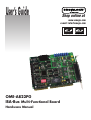
User’s Guide
OME-A822PG
ISA-Bus
Multi-Functional Board
Hardware Manual
Shop online at

Servicing North America:
USA: One Omega Drive, P.O. Box 4047
ISO 9001 Certified Stamford CT 06907-0047
TEL: (203) 359-1660 FAX: (203) 359-7700
e-mail: [email protected]
Canada: 976 Bergar
Laval (Quebec) H7L 5A1, Canada
TEL: (514) 856-6928 FAX: (514) 856-6886
e-mail: [email protected]
For immediate technical or application assistance:
USA and Canada: Sales Service: 1-800-826-6342 / 1-800-TC-OMEGA
®
Customer Service: 1-800-622-2378 / 1-800-622-BEST
®
Engineering Service: 1-800-872-9436 / 1-800-USA-WHEN
®
TELEX: 996404 EASYLINK: 62968934 CABLE: OMEGA
Mexico: En Espan˜ol: (001) 203-359-7803 e-mail: [email protected]
FAX: (001) 203-359-7807 [email protected]
Servicing Europe:
Benelux: Postbus 8034, 1180 LA Amstelveen, The Netherlands
TEL: +31 (0)20 3472121 FAX: +31 (0)20 6434643
Toll Free in Benelux: 0800 0993344
e-mail: [email protected]
Czech Republic: Frystatska 184, 733 01 Karviná, Czech Republic
TEL: +420 (0)59 6311899 FAX: +420 (0)59 6311114
Toll Free: 0800-1-66342 e-mail: [email protected]
France: 11, rue Jacques Cartier, 78280 Guyancourt, France
TEL: +33 (0)1 61 37 29 00 FAX: +33 (0)1 30 57 54 27
Toll Free in France: 0800 466 342
e-mail: [email protected]
Germany/Austria: Daimlerstrasse 26, D-75392 Deckenpfronn, Germany
TEL: +49 (0)7056 9398-0 FAX: +49 (0)7056 9398-29
Toll Free in Germany: 0800 639 7678
e-mail: [email protected]
United Kingdom: One Omega Drive, River Bend Technology Centre
ISO 9002 Certified Northbank, Irlam, Manchester
M44 5BD United Kingdom
TEL: +44 (0)161 777 6611 FAX: +44 (0)161 777 6622
Toll Free in United Kingdom: 0800-488-488
e-mail: [email protected]
OMEGAnet
®
Online Service Internet e-mail
www.omega.com [email protected]
It is the policy of OMEGA to comply with all worldwide safety and EMC/EMI regulations that
apply. OMEGA is constantly pursuing certification of its products to the European New Approach
Directives. OMEGA will add the CE mark to every appropriate device upon certification.
The information contained in this document is believed to be correct, but OMEGA Engineering, Inc. accepts
no liability for any errors it contains, and reserves the right to alter specifications without notice.
WARNING: These products are not designed for use in, and should not be used for, patient-connected applications.

OME-A-822PGH/PGL
Enhanced Multi-Function Card
Hardware Manual
OME-A-822PGL/PGH Hardware Manual ---- 1

Tables of Contents
1. Introduction_________________________________________________________ 4
1.1 General Description __________________________________________________ 4
1.2 Features _____________________________________________________________ 4
1.3 Specifications _________________________________________________________ 5
1.3.1 Power Consumption : ________________________________________________________ 5
1.3.2 Analog Inputs ______________________________________________________________ 5
1.3.3 A/D Converter _____________________________________________________________ 5
1.3.4 DA Converter ______________________________________________________________ 6
1.3.5 Digital I/O_________________________________________________________________ 6
1.3.6 Interrupt Channel ___________________________________________________________ 6
1.3.7 Programmable Timer/Counter _________________________________________________ 7
1.3.8 Direct Memory Access Channel (DMA) _________________________________________ 7
1.4 Applications __________________________________________________________ 8
1.5 Product Check List ____________________________________________________ 8
2. Hardware Configuration ______________________________________________ 9
2.1 Board Layout_________________________________________________________ 9
2.2 I/O Base Address Setting ______________________________________________ 10
2.3 Jumper Settings______________________________________________________ 11
2.3.1 JP1 : D/A Internal Reference Voltage Selection___________________________________ 11
2.3.2 JP2 : D/A Int/Ext Ref Voltage Selection ________________________________________ 12
2.3.3 JP3 : Single-ended/Differential Selection________________________________________ 12
2.3.4 JP4 : A/D Trigger Source Selection ____________________________________________ 13
2.3.5 JP5 : Interrupt Level Selection ________________________________________________ 13
2.3.6 JP6 : User Timer/Counter Clock Input Selection __________________________________ 14
2.3.7 JP7 : DMA DACK Selection, JP8 : DMA DRQ Selection _____________________ 15
2.4 I/O Register Address__________________________________________________ 16
2.4.1 8254 Counter _____________________________________________________________ 17
2.4.2 A/D Input Buffer Register ___________________________________________________ 17
2.4.3 D/A Output Latch Register___________________________________________________ 18
2.4.4 D/I Input Buffer Register ____________________________________________________ 19
2.4.5 Clear Interrupt Request______________________________________________________ 19
2.4.6 A/D Gain Control Register ___________________________________________________ 20
2.4.7 A/D Multiplex Control Register _______________________________________________ 21
2.4.8 A/D Mode Control Register __________________________________________________ 22
OME-A-822PGL/PGH Hardware Manual ---- 2

2.4.9 A/D Software Trigger Control Register _________________________________________ 23
2.4.10 D/O Output Latch Register __________________________________________________ 24
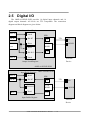
2.5 Digital I/O __________________________________________________________ 25
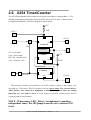
2.6 8254 Timer/Counter __________________________________________________ 26
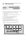
2.7 A/D Conversion ______________________________________________________ 27
2.7.1 A/D conversion flow________________________________________________________ 28
2.7.2 A/D Conversion Trigger Modes _______________________________________________ 29
2.7.3 A/D Transfer Modes________________________________________________________ 29
2.7.4 Using software trigger and polling transfer ______________________________________ 30
2.8 D/A Conversion ______________________________________________________ 31
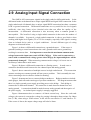
2.9 Analog Input Signal Connection _________________________________________ 32
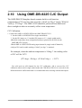
2.10 Using OME-DB-8225 CJC Output ______________________________________ 36
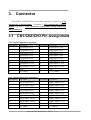
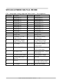
3. Connector _________________________________________________________ 37
3.1 CN1/CN2/CN3 Pin Assignment _________________________________________ 37
3.2 Daughter Board________________________________________________________ 40
3.2.1 OME-DB-8225 ____________________________________________________________ 40
3.2.2 OME-DB-37 ______________________________________________________________ 40
3.2.3 OME-DB-16P_____________________________________________________________ 40
3.2.4 OME-DB-16R_____________________________________________________________ 40
4. Calibration___________________________________________________________ 41
4.1 Description of Variable Resistors ________________________________________ 41
4.2 D/A Calibration______________________________________________________ 42
4.3 A/D Calibration______________________________________________________ 43
5. Diagnostic Utility____________________________________________________ 44
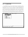
5.1 Introduction_________________________________________________________ 44
5.2 Running The Diagnostic Utility _________________________________________ 46
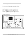
5.2.1 Setup ____________________________________________________________________ 47
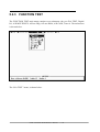
5.2.2 CALIBRATION ___________________________________________________________ 49
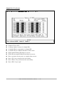
5.2.3 FUNCTION TEST _________________________________________________________ 50
5.2.4 SPECIAL TEST ___________________________________________________________ 58
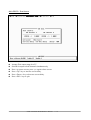
5.2.5 Help ____________________________________________________________________ 59
OME-A-822PGL/PGH Hardware Manual ---- 3

1. Introduction
1.1 General Description
The OME-A-822PGL/PGH is a high performance, multifunction analog, digital I/O
board for PC AT compatible computers. The OME-A-822PGL provides low gain (0.5,1, 2, 4,
8). The OME-A-822PGH provides high gain (0.5,1,5,10,50,100,500,1000). The
OME-A-822PGL/PGH contains a 12-bit ADC with up to 16 single-ended or 8 differential
analog inputs. The maximum sample rate of the A/D converter is 100Ksample/sec. There are
two 12-bit DACs with voltage output, 16 channels of TTL-compatible digital input, 16
channels of TTL-compatible digital output and one 16-bit counter/timer channel for timing
input and output.
The following A/D performance bench marks were achieved on a 33MHz 486
computer:
z Polling mode : about 100Ksample/sec (with single-task OS)
z Interrupt mode : about 60Ksample/sec (with single-task OS)
z DMA mode : about 100Ksample/sec (with single-task OS)
1.2 Features
z The maximum sample rate of the A/D converter is 100 K samples/sec
z Software selectable input ranges
z PC AT compatible ISA bus
z A/D trigger mode : software trigger , pacer trigger, external trigger
z 16 single-ended or 8 differential analog input signals
z Programmable high gain : 0.5,1,5,10,50,100,500,1000 (OME-A-822PGH)
z Programmable low gain : 0.5,1,2,4,8 (OME-A-822PGL)
z 2 channel 12-bit D/A voltage output
z 16 digital input /16 digital output (TTL compatible)
z Interrupt handling
z Bipolar/Unipolar operation
z 1 channel general purpose programmable 16 bit timer/counter
OME-A-822PGL/PGH Hardware Manual ---- 4

1.3 Specifications
1.3.1 Power Consumption :
z +5V @960 mA maximum, OME-A-822PGL/PGH
z Operating temperature : -20°C to 60°C
1.3.2 Analog Inputs
z Channels : 16 single-ended or 8 differential
z Input range : (software programmable)
OME-A-822PGL:bipolar : ±10V,±5V, ±2.5V, ±1.25V, ±0.0625V
unipolar : 0 to 10V, 0 to 5V, 0 to 0.2.5V, 0 to 1.25.V
OME-A-822PGH:bipolar : ±10,±5V,±1V, ±0.5V, ±0.1V, ±0.05V, ±0.01V, ± 0.005V
unipolar : 0 to 10V, 0 to 1V, 0 to 0.1V, 0 to 0.01V
z Input current : 250 nA max (125 nA typical ) at 25 deg. C
z On chip sample and hold
z Over voltage : continuous single channel to
70Vp-p
z Input impedance : 10 Ω // 6pF
Caution: refer to
Sec. 2.9 first
10
1.3.3 A/D Converter
z Type : successive approximation , Burr Brown ADS 774 or SIPEX-SP774B
( equivalent)
z Conversion time : 8 microsec.
z Accuracy : +/- 1 bit
z Resolution : 12 bits
OME-A-822PGL/PGH Hardware Manual ---- 5

1.3.4 DA Converter
z Channels : 2 independent
z type : 12 bit multiplying , Analog device AD-7541
z Linearity : +/- 1/2 bit
z Output range : 0 to 5V or 0 to 10V jumper selected , may be used with other
AC or DC reference input. Maximum output limit +/- 10V
z Output drive : +/- 5mA
z settling time : 0.6 microseconds to 0.01% for full scale step
1.3.5 Digital I/O
z Output port : 16 bits, TTL compatible
Output Low: VOL=05.Vmax @IOL = 8 mA max
Output High: VOH = 2.7Vmin @IOH = -400µA max
z Input port : 16 bits, TTL compatible
Input Low: VIL=0.8V max; IIL = -0.4mA max
Input High: VIH=2.0V min; IIL = 20µA max
1.3.6 Interrupt Channel
z Level : 3,4,5,6,7,10,11,12,14,15, jumper selectable
z Enable : Via control register
OME-A-822PGL/PGH Hardware Manual ---- 6

1.3.7 Programmable Timer/Counter
z Type : 82C54 -8 programmable timer/counter
z Counters : Counter1 and counter2 are cascaded as a 32 bit pacer timer.
Counter0 is a user available timer/counter. The software driver also uses
counter0 to implement a machine independent timer.
z Clock input frequency : DC to 10 MHz
z Pacer output : 0.00047Hz to 0.5MHz
z Input ,gate : TTL compatible
z Internal Clock : 2 MHz
1.3.8 Direct Memory Access Channel (DMA)
z Level : CH1 or CH3, jumper selectable
z Enable : via DMA bit of control register
z Termination : by interrupt on T/C
z Transfer rate : 100K conversions/sec.
OME-A-822PGL/PGH Hardware Manual ---- 7

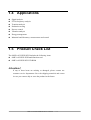
1.4 Applications
z Signal analysis
z FFT & frequency analysis
z Transient analysis
z Production testing
z Process control
z Vibration analysis
z Energy management
z Industrial and laboratory. measurement and control
1.5 Product Check List
The OME-A-8322PGL/PGH includes the following items:
z OME-A-822PGL/PGH multifunction card
z OME-A-822PGL/PGH CD ROM
Attention !
If any of these items are missing or damaged, please contact our
customer service department. Save the shipping materials and carton
in case you want to ship or store the product in the future.
OME-A-822PGL/PGH Hardware Manual ---- 8

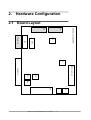
2. Hardware Configuration
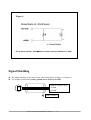
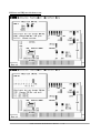
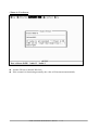
2.1 Board Layout
OME-A-822PGL/PGH
VR1/2/3/4/5/6/7
ISA BUS ISA BUS
CN2
CN1
JP5
SW1
CN3
JP3
JP6
JP8 JP7
JP4
JP1
JP2
OME-A-822PGL/PGH Hardware Manual ---- 9

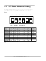
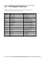
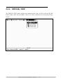
2.2 I/O Base Address Setting
The OME-A-822PGL/PGH occupies 16 consecutive locations in I/O address
space. The base address is set by DIP switch SW1. The default address is
0x220.
A9 A8 A7 A6 A5 A4
6 5 4 3 2 1
ON
SW1 : BASE ADDRESS
BASE
ADDR
A9 A8 A7 A6 A5 A4
200-20F OFF ON ON ON ON ON
210-21F OFF ON ON ON ON OFF
220-22F(;) OFF ON ON ON OFF ON
230-23F OFF ON ON ON OFF OFF
: : : : : : :
300-30F OFF OFF ON ON ON ON
: : : : : : :
3F0-3FF OFF OFF OFF OFF OFF
(;) : default base address is 0x220
OME-A-822PGL/PGH Hardware Manual ---- 10

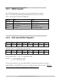
The PC I/O port map is given below.
ADDRESS Device ADDRESS DEVICE
000-1FF PC reserved 320-32F XT Hard Disk
200-20F Game/control 378-37F Parallel Printer
210-21F XT Expansion Unit 380-38F SDLC
238-23F Bus Mouse/Alt. Bus Mouse 3A0-3AF SDLC
278-27F Parallel Printer 3B0-3BF MDA/Parallel Printer
2B0-2DF EGA 3C0-3CF EGA
2E0-2E7 AT GPIB 3D0-3DF CGA
2E8-2EF Serial Port 3E8-3EF Serial Port
2F8-2FF Serial Port 3F0-3F7 Floppy Disk
300-31F Prototype Card 3F8-3FF Serial Port
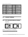
2.3 Jumper Settings
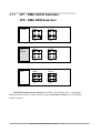
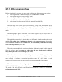
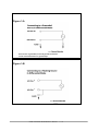
2.3.1 JP1 : D/A Internal Reference Voltage
Selection
Reference
Voltage
-5V
(default)
1
2
3
(
-10V
)
(-5V)
Reference
Voltage
-10V
1
2
3
(
-10V
)
(-5V)
Select (-5V) : D/A voltage output = 0 to 5V (both channel)
Select (-10V) : D/A voltage output = 0 to 10V (both channel)
JP1 is valid only if JP2 is set to D/A internal reference voltage
OME-A-822PGL/PGH Hardware Manual ---- 11

2.3.2 JP2 : D/A Int/Ext Ref Voltage Selection
If JP2 is set to internal reference, then JP1 should be set to -5V or -10V internal reference
voltage.
If JP2 is set to external reference, then ExtRef1, CN3 pin 31, is the external reference
voltage for D/A channel 1. and ExtRef2, CN3 pin 12, is the external reference voltage for
D/A Channel 2.
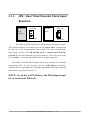
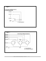
2.3.3 JP3 : Single-ended/Differential Selection
Ch 1 = INT
Ch 2 = INT
(default)
JP2
(
vref
)
Ch 1 =EXT
(ExtRef1)
Ch 2 =EXT
(ExtRef2)
JP2
(
vref
)
Ch 1 = INT
Ch 2 =EXT
(ExtRef2)
JP2
(
vref
)
Ch 1 =EXT
(ExtRef1)
Ch 2 = INT
JP2
(
vref
)
DIFF
SINGLE
Single-ended
(default)
SINGLE
DIFF
Differential
The OME-A-822PGL/PGH offers 16 single-ended or 8 differential analog input channels.
The JP3 jumper sets the inputs to single-ended or differential mode. You can not select
single-ended and differential simultaneously.
Refer to Sec. 2.9 first.
OME-A-822PGL/PGH Hardware Manual ---- 12

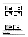
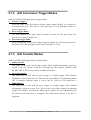
2.3.4 JP4 : A/D Trigger Source Selection
EXTTRG
INTTRG
Internal
Trigger
(default)
EXTTRG
INTTRG
External
Trigger
The OME-A-822PGL/PGH supports two trigger types, internal trigger and
external trigger. The external trigger comes from ExtTrg, CN3 pin 17.
There are two types of internal triggers, software trigger and pacer trigger.
More detailed information is given in section 2.4.8.
2.3.5 JP5 : Interrupt Level Selection
NO Interrupt
IRQ 3 4 5 6 7 9 10 11 12 14 15 NC
Interrupt 15
(default)
IRQ 3 4 5 6 7 9 10 11 12 14 15 NC
The interrupt channel can not be shared. The OME-A-822 software driver can support
8 different cards in one system but only 2 of these cards can use the interrupt transfer
function.
OME-A-822PGL/PGH Hardware Manual ---- 13

2.3.6 JP6 : User Timer/Counter Clock Input
Selection
Internal 2M
Clock
(default)
INTCL
K
EXTCLK
External
Clock
INTCL
K
EXTCLK
The OME-A-822PGL/PGH has 3 independent 16 bit timer/counters.
The cascaded counter1 and counter2 are used as a pacer timer. Counter0 can
be used as a user programmable timer/counter. The user programmable
timer/counter can be set to 2M internal clock or external clock ExtCLK,
CN3 pin 37. The block diagram is given in section 2.6. The clock source must
be very stable. Using the 2M internal clock is strongly suggested.
The OME-A-822PGL/PGH software driver uses counter0 as a machine
independent timer. If users program calls the A-822_Delay() subroutine,
counter0 will be programmed as a machine independent timer. More detailed
information is provided in section 2.6.
NOTE : if you use A-822_Delay(), the JP6 jumper must
be set to internal 2M clock.
OME-A-822PGL/PGH Hardware Manual ---- 14

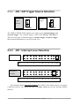
2.3.7 JP7 : DMA DACK Selection,
JP8 : DMA DRQ Selection
JP8
DAC
K
2
6
1
5
JP7
DR
Q
2
6
1
5
NO DMA
JP8
JP7
1
5
2
6
DR
Q
1
5
2
6
DAC
K
DMA 1
(default)
JP8
JP7
1
5
2
6
DR
Q
DAC
K
1
5
2
6
DMA 3
The DMA channel can not shared. The OME-A-822 software driver can support 8
different boards in one PC based system, but only two of these boards can use the DMA
transfer function.
OME-A-822PGL/PGH Hardware Manual ---- 15

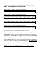
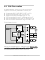
2.4 I/O Register Address
The OME-A-822PGL/PGH occupies 16 consecutive PC I/O addresses. The
following table lists the registers and their locations.
Address Read Write
Base+0 8254 Counter 0 8254 Counter 0
Base+1 8254 Counter 1 8254 Counter 1
Base+2 8254 Counter 2 8254 Counter 2
Base+3 Reserved 8254 Counter Control
Base+4 A/D Low Byte D/A Channel 0 Low Byte
Base+5 A/D High Byte D/A Channel 0 High Byte
Base+6 DI Low Byte D/A Channel 1 Low Byte
Base+7 DI High Byte D/A Channel 1 High Byte
Base+8 Reserved A/D Clear Interrupt Request
Base+9 Reserved A/D Gain Control
Base+A Reserved A/D Multiplexer Control
Base+B Reserved A/D Mode Control
Base+C Reserved A/D Software Trigger Control
Base+D Reserved DO Low Byte
Base+E Reserved DO High Byte
Base+F Reserved Reserved
OME-A-822PGL/PGH Hardware Manual ---- 16

2.4.1 8254 Counter
The 8254 Programmable timer/counter has 4 registers from Base+0 through
Base+3. For detailed programming information on the 8254 , please refer to
Intel‘s “Microsystem Components Handbook”.
Address Read Write
Base+0 8254 Counter 0 8254 Counter 0
Base+1 8254 Counter 1 8254 Counter 1
Base+2 8254 Counter 2 8254 Counter 2
Base+3 Reserved 8254 Counter Control
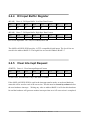
2.4.2 A/D Input Buffer Register
(READ) Base+4 : A/D Low Byte Data Format
Bit 7 Bit 6 Bit 5 Bit 4 Bit 3 Bit 2 Bit 1 Bit 0
D7 D6 D5 D4 D3 D2 D1 D0
(READ) Base+5 : A/D High Byte Data Format
Bit 7 Bit 6 Bit 5 Bit 4 Bit 3 Bit 2 Bit 1 Bit 0
0 0 0 READY D11 D10 D9 D8
A/D 12 bit data : D11…..D0, D11=MSB, D0=LSB
READY =1 : A/D 12 bit data not ready
=0 : A/D 12 bit data is ready
The low 8 bit A/D data is stored in address BASE+4 and the high 4 bit data is stored in
address BASE+5. The READY bit is used as an indicator for the A/D conversion. When an
A/D conversion is completed, the READY bit will clear to zero.
OME-A-822PGL/PGH Hardware Manual ---- 17

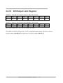
2.4.3 D/A Output Latch Register
(WRITE) Base+4 : Channel 1 D/A Low Byte Data Format
Bit 7 Bit 6 Bit 5 Bit 4 Bit 3 Bit 2 Bit 1 Bit 0
D7 D6 D5 D4 D3 D2 D1 D0
(WRITE) Base+5 :Channel 1 D/A High Byte Data Format
Bit 7 Bit 6 Bit 5 Bit 4 Bit 3 Bit 2 Bit 1 Bit 0
X X X X D11 D10 D9 D8
(WRITE) Base+6 : Channel 2 D/A Low Byte Data Format
Bit 7 Bit 6 Bit 5 Bit 4 Bit 3 Bit 2 Bit 1 Bit 0
D7 D6 D5 D4 D3 D2 D1 D0
(WRITE) Base+7 :Channel 2 D/A High Byte Data Format
Bit 7 Bit 6 Bit 5 Bit 4 Bit 3 Bit 2 Bit 1 Bit 0
X X X X D11 D10 D9 D8
D/A 12 bit output data: D11..D0, D11=MSB, D0=LSB, X=don‘t care
The D/A converter will convert the 12 bit digital data to an analog output. The lower 8 bits
of D/A channel 1 are stored in the address BASE+4 and the high 4 bits are stored in the
address BASE+5. The address BASE+6 and BASE+7 store the 12 bit data for D/A channel
2. The D/A output latch registers are designed with a “double buffered” structure, so the
analog output latch registers will not update until the high 4 bit digital data are written. If the
user sends the high 4 bit data first, the D/A 12 bit output latch registers will update at once.
So the lower 8 bits will be the previous data latched in the register. This action will cause
an error on the D/A output voltage. The user must send the low 8 bits first and then
send the high 4 bits to update the 12 bit D/A output latch register.
NOTE : Send the low 8 bits first, then send the high 4 bits.
OME-A-822PGL/PGH Hardware Manual ---- 18
Page is loading ...
Page is loading ...
Page is loading ...
Page is loading ...
Page is loading ...
Page is loading ...
Page is loading ...
Page is loading ...
Page is loading ...
Page is loading ...
Page is loading ...
Page is loading ...
Page is loading ...
Page is loading ...
Page is loading ...
Page is loading ...
Page is loading ...
Page is loading ...
Page is loading ...
Page is loading ...
Page is loading ...
Page is loading ...
Page is loading ...
Page is loading ...
Page is loading ...
Page is loading ...
Page is loading ...
Page is loading ...
Page is loading ...
Page is loading ...
Page is loading ...
Page is loading ...
Page is loading ...
Page is loading ...
Page is loading ...
Page is loading ...
Page is loading ...
Page is loading ...
Page is loading ...
Page is loading ...
Page is loading ...
Page is loading ...
Page is loading ...
-
 1
1
-
 2
2
-
 3
3
-
 4
4
-
 5
5
-
 6
6
-
 7
7
-
 8
8
-
 9
9
-
 10
10
-
 11
11
-
 12
12
-
 13
13
-
 14
14
-
 15
15
-
 16
16
-
 17
17
-
 18
18
-
 19
19
-
 20
20
-
 21
21
-
 22
22
-
 23
23
-
 24
24
-
 25
25
-
 26
26
-
 27
27
-
 28
28
-
 29
29
-
 30
30
-
 31
31
-
 32
32
-
 33
33
-
 34
34
-
 35
35
-
 36
36
-
 37
37
-
 38
38
-
 39
39
-
 40
40
-
 41
41
-
 42
42
-
 43
43
-
 44
44
-
 45
45
-
 46
46
-
 47
47
-
 48
48
-
 49
49
-
 50
50
-
 51
51
-
 52
52
-
 53
53
-
 54
54
-
 55
55
-
 56
56
-
 57
57
-
 58
58
-
 59
59
-
 60
60
-
 61
61
-
 62
62
-
 63
63


Ask a question and I''ll find the answer in the document
Finding information in a document is now easier with AI
Related papers
-
Omega OME Series Boards Owner's manual
-
Omega OME-WISE-7000 Series Owner's manual
-
-
-
Omega DRA-RTM-8 User manual
-
-
Omega Speaker Systems OME-DB-889D User manual
-
-
Omega USB-4751/USB-4751L Owner's manual
-
Other documents
-
ICP A-823PGH User manual
-
-
 Ack!Industries dAck! User manual
-
Eurotech Advme2608A Owner's manual
-
ELK 960 Specification
-
-
Diamond Systems Diamond-MM User manual
-
ADLINK Technology NuDAQ ACL-8216 User manual
-
Eurotherm 392 Operating instructions
-
