Page is loading ...

MAINTENANCE MANUAL
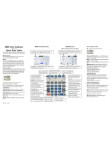
Site Master™ Model S113BQ
Antenna and Cable Analyzers
1. INTRODUCTION
This manual provides maintenance instructions for the Site
Master S113BQ Antenna and Cable Analyzer. It describes
the product and provides performance verification proce
-
dures, parts replacement procedures, and a replaceable parts
list.
2. DESCRIPTION
The Site Master S113BQ (Figure 1) is a hand held SWR/RL
(standing wave ratio/return loss), and Distance-To-Fault
measurement instrument. It combines a synthesized source,
VSWR Bridge, and receiver on a single printed circuit board
(PCB). An optional power monitor is also available. A block
diagram is shown in Figure 2.
3. PERFORMANCE VERIFICATION
Paragraphs 4 through 9 contain tests that can be used to ver-
ify the performance of the Site Master Model S113BQ.
3.1. Initial Setup for Testing
1. Press and hold the
ESCAPE/CLEAR key, then
press the
ON/OFF key to turn on the Site Mas
-
ter. (This sets the instrument to the factory pre
-
set state.)
2. Release the
ESCAPE/CLEAR key and use the
Up/Down arrow key to adjust the contrast to
give a readable display.
HOLD
RUN
START
CAL
AUTO
SCALE
SAVE
SETUP
RECALL
SETUP
LIMIT
MARKER
SAVE
DISPLAY
RECALL
DISPLAY
PRINT
MODE
FREQ/DIST
AMPLITUDE
SWEEP
SYS
ENTER
CLEAR
ESCAPE
ON
OFF
/
1
2
4
5
6
7
8
9
0
3
+
-
.
Site Master S113BQ
2.00
791.12 MHz
400.43 MHz
1000.00
Figure 1. Site Master Model S113BQ
490 JARVIS DRIVE · MORGAN HILL, CA 95037-2809
P/N: 10580-00121
REVISION A
PRINTED: AUGUST 2004
COPYRIGHT ã 2004 ANRITSU CO.

4. FREQUENCY ACCURACY
The following test can be used to verify the CW frequency
accuracy of the Site Master. Measurement calibration of the
Site Master is not required for this test.
a. Equipment Required:
·
Spectrum Analyzer Anritsu Model MS2663C
or equivalent
b. Procedure:
1. Press and hold the
ESCAPE/CLEAR key, then
press the
ON/OFF key to turn on the Site Mas
-
ter. (This sets the instrument to the factory pre
-
set state.)
NOTE
Before continuing, allow a five minute
warm up for the internal circuitry to sta
-
bilize.
2. Press the
FREQ/DIST key, then press the F1
soft key and set F1 to 1000 MHz, then press the
ENTER key.
3. Press the
F2 soft key, set F2 to 1000 MHz, then
press the
ENTER key.
4. Connect the RF cable from the Site Master Re-
flection Test Port to the RF Input on the
MS2663C or equivalent.
5. Set up the Spectrum Analyzer as follows:
(a)
Press the
Preset key, then select Preset
All
(F1).
(b)
Press the
Frequency key.
(c)
Press the
1 key and then the GHz key to
change the Center Frequency to 1 GHz.
(d)
Press the
Span key.
(e)
Press the
2, 5, 0, and kHz keys sequen
-
tially to change the Frequency Span to 250
kHz.
(f)
Press the
RBW key.
(g)
Press the
3, 0 and kHz keys sequentially
to change the RBW to 30 kHz.
(h)
Press the VBW key.
2 Site Master S113BQ MM
LO
x
x
Divider/
M u ltip lie r
SD
C oupler
SD
ADC
Test
Port
Display
CPU
Serial
Port
RF
Source
Figure 2. Site Master Block Diagram

(i)
Press
the Filter Off soft key (F3) to turn
the VB filter off.
(j)
Press the
Amplitude key.
(k)
Press the
0, and dBm keys sequentially to
change the Reference Level to 0 dBm.
(l)
Press the
Log Scale soft key (F5)
(m)
Select
2 dB/Div (F3) and the press the re
-
turn
soft key (F6).
(n)
Press the
Marker key.
(o)
Press the
Zone Width soft key (F5).
(p)
Select the
Spot soft key (F1).
6. On the Site Master, press the
SYS key, the OP
-
TIONS
soft key and then the FIXED CW soft
key to turn Fixed CW on.
NOTE:
If the Site Master has gone into the hold
mode, press the
RUN/HOLD key to return to
normal mode.
7. When a sweep is completed, a smooth response
should appear on the Spectrum Analyzer.
8.
Press the
Marker Peak Search key on the
Spectrum Analyzer. Verify that the marker peak
readout value is 1000 MHz ±75 kHz.
9. On the Site Master, press the
SYS key, the OP-
TIONS
soft key and then the FIXED CW soft
key to turn Fixed CW Off.
5. RETURN LOSS VERIFICATION
The following test can be used to verify the accuracy of re
-
turn loss measurements. Measurement calibration of the Site
Master is required for this test.
a. Equipment Required:
·
20 dB offset, Anritsu SC5270
·
6 dB offset, Anritsu SC5237
·
Open/Short, Anritsu 22N50
·
50 Ohm Termination,
Anritsu 28N50-2 or SM/PL
b. Procedure:
1. Press and hold the
ESCAPE/CLEAR key, then
press the
ON/OFF key to turn on the Site Mas
-
ter. (This sets the instrument to the factory pre
-
set state.)
NOTE
Before continuing, allow a five minute
warm up for the internal circuitry to sta-
bilize.
2. Press the
MODE soft key.
3. Use the Up/Down Arrow key to highlight
RE-
TURN LOSS
, then press ENTER.
4. Press the
START CAL key.
5. Follow the instructions on the screen to per
-
form a calibration using a 22N50 Open/Short
and 28N50-2 or SM/PL Termination.
6. Connect the 20 dB offset to the Refl Test Port
and verify that the reading is:
q
S113BQ: 20 dB ± 1.7 dB
7. Connect the 6 dB offset to the Refl Test Port
and verify that the reading is:
q
S113BQ: 6 dB ± 1.2 dB
Site Master S113BQ MM 3

6. POWER MONITOR VERIFICATION
If the Power Monitor (Option 5) is installed in the Site Mas-
ter, the following test can be used to verify the accuracy of
the power measurements. Measurement calibration of the
Site Master is not required for this test.
a. Equipment Required:
· RF Detector, 10 MHz to 20 GHz,
Anritsu 560-7N50B
·
10 dB Attenuator, Weinschel 1R-10
·
30 dB Attenuator, Weinschel 1R-30
·
RF Reference Source, 0.050 GHz,
Anritsu MA2418A
·
DC Power Supply, Anritsu 2000-933
b. Procedure
1. Connect the DC power supply to the MA2418A
Reference Source. (Refer to Figure 3, page 4.)
2. Connect the MA2418A Reference Source to
the input of the 560-7N50B RF detector.
3. Connect the RF Detector output to the RF De
-
tector input of the Site Master.
4. Connect the DC power supply to the appropri
-
ate line voltage to supply power to the
MA2418A Reference Source.
5. Press and hold the ESCAPE/CLEAR key, then
press the
ON/OFF key to turn on the Site Mas-
ter. (This sets the instrument to the factory pre-
set state.)
6. Press the
MODE soft key.
7. Use the Up/Down Arrow key to highlight
POWER MONITOR, then press ENTER.
8. Press the
ZERO soft key to zero the power
monitor.
When complete,
ZERO ADJ:ON is displayed in
the message area.
9. Verify that the power monitor reading is
0.0 dBm ± 1 dB.
10. Connect the output of the MA2418A Reference
Source to the two attenuators so as to add 40
dB of attenuation (Figure 3).
11. Connect the MA2418A Reference Source and
the attenuators to the input of the 560-7N50B
RF detector.
12. Verify that the power monitor reading is now
–40.0 dBm ±2 dB.
7. TERMINATION VERIFICATION
This test verifies the accuracy of the Site Master SM/PL ter
-
mination using the precision return loss mode of the
541XXA Scalar Measurement System. Measurements of ter
-
minations using this mode provide results that are traceable
4 Site Master S113BQ MM
DC Power Supply 2000-933
A
ttenuators
Site Master w/ O
p
tion5Installed
MA2418A
Reference Source
560-7N50B
RF Detector
15-24V DC
20 mA
MA2418A Reference Source
50 MHz, 50
0dBm
W
HOLD
RUN
START
CAL
AUTO
SCALE
SAVE
SETUP
RECALL
SETUP
LIMIT
MARKER
SAVE
DISPLAY
RECALL
DISPLAY
PRINT
MODE
FREQ/DIST
AMPLITUDE
SWEEP
SYS
ENTER
CLEAR
ESCAPE
ON
OFF
/
1
2
4
5
6
7
8
9
0
3
+
-
.
Site Master S113BQ
2.00
791.12 MHz
400.43 MHz
1000.00
Figure 3. Power Monitor Verification

to the NIST (National Institute of Standards and Technology)
standards for the precision airline.
a. Equipment Required:
· Scalar Measurement System,
Anritsu 541XXA
· Offset SWR Autotester,
Anritsu 560-97A50-20
·
Precision Airline, Anritsu 18N50
·
Open/Short, Anritsu 22N50
·
50 Ohm Termination, Anritsu 26N50
·
Source Adapter, Anritsu 34NN50A
b. Procedure
1. Connect the test equipment as shown in Figure
4, page 5.
2. Press the
Power key on the 541XXA to On.
3. Press the
System Menu key.
4. Using the Menu up-down keys: Highlight
RE
-
SET
, then press the Select key.
5. At the
RESET MENU display, use the Menu
up-down keys to highlight
RESET TO FAC
-
TORY DEFAULTS
, then press the Select key.
6. Set the signal source for the frequency range as
follows:
(a) Press the
Frequency key.
(b) Using the Data Entry Keypad or Data En-
try Knob, set the Start frequency to
0.01 GHz. Press the
Enter key.
(c) Using the Data Entry Keypad or Data En-
try Knob, set the Stop frequency to
4.0 GHz. Press the
Enter key.
7. Press the Channel 2 Display On/Off key to Off.
8. Press the Channel 1 Menu key.
9. Using the Menu up-down keys: Highlight
PRE
-
CISION RL
, then press the Select key.
10. At the PRECISION RETURN LOSS menu dis
-
play, use the Menu up-down keys to highlight
FINAL, then press the Select key.
11. Press the
Calibration key.
12. At the CALIBRATION menu display, use the
Menu up-down keys to highlight
START CAL,
then press the
Select key.
13. At the PRECISION RETURN LOSS CALI
-
BRATION menu display prompt, connect the
Offset SWR Autotester to Input A, if you have
not done so yet.
14. Connect the precision air line to the Offset
SWR Autotester test port. Position the air line
Site Master S113BQ MM 5
541XXA Scalar Measurement System
Connect Dashed Line Connections
When Directed By Procedure
Precision
Air Line
Open/Short
Source
Adapter
50 Ohm
Termination
Offset SWR
Autotester
Termination
under Test
A
B
Beadless
End
Figure 4. 541XXA Precision Return Loss Setup

pointing vertically upward. Downward or hori
-
zontal positions make connector pin alignment
difficult.
NOTE
Ensure that the beadless end of the pre
-
cision airline is at the measurement con
-
nection point.
15. Press the
Select key when ready.
16. At the PRECISION RETURN LOSS CALI
-
BRATION menu prompt, connect the Open to
the beadless end of the airline. Press the
Select
key to start the calibration.
17. Verify that the display resembles that shown in
Figure 5.
CAUTION
During both calibration and measure
-
ment, be sure to properly align the
beadless connector of the airline. When
the connectors are mis-aligned, a spike
will usually be visible on the display.
18. At the next menu prompt, remove the Open and
connect the Short to the beadless end of the air
-
line. Press the
Select key to start the calibration
process.
19. At the next menu prompt, remove the Short and
connect the 50 Ohm Termination to the
beadless end of the air line. Press the Select
key to start the calibration process.
20. When the calibration is complete, remove the
50 Ohm Termination.
21. Connect the SM/PL termination to the beadless
end of the air line and press the Select key to
begin the measurement.
22. Observe that the waveform displayed resembles
that shown in Figure 6.
23. Press the
Cursor On/Off key to On.
24. Observe the Cursor menu readout. The mini
-
mum return loss reading for the SM/PL termi
-
nation should be 42 dB.
6 Site Master S113BQ MM
1 0 .0 d B /D IV O F F S E T1: PRECSN RL (A)
2: O FF
+0.0dB
0.4 G H z/D IV
START: 0.0100 G Hz
401 pts
STO P : 4.0000 G H z
LEVE L +7.0 dB m
54147A
PRECISION
RETURN LOSS
CALIBRATION
CONNECT OPEN
T O A IR L IN E
PRESS SELECT
W HEN READY
Figure 5. Example of a Good Connection
1 0 .0 d B /D IV O F F S E T1: PRECSN RL (A)
2: O FF
+0.0dB
0.4 G H z/D IV
START: 0.0100 G Hz
401 pts
STO P : 4.0000 G H z
LEVE L +7.0 dB m
54147A
CURSOR
1: -46.02 dB
PRESS SELECT
FO R
CURSOR MENU
2.4050 G H z
Figure 6. Direct Readout of the Precision Return Loss

8. BATTERY PACK REMOVAL AND
REPLACEMENT
This procedure provides instructions for removing and re
-
placing the Site Master battery pack.
1. With the Site Master standing upright on a stable
surface, locate the battery access door (Figure 7).
2. Lift up the access door handle and rotate it 90 de-
grees counterclockwise, as illustrated in Figure 8.
3. Lift the door and remove, as illustrated in Figure 9.
4. Grasp the battery lanyard and pull the battery
straight up and out of the unit, as illustrated in Fig
-
ure .
5. Replacement is the opposite of removal. Note the
orientation of the battery contacts, and be sure to in
-
sert the new battery with the contacts facing the rear
of the unit (Figure 11).
Site Master S113BQ MM 7
BATTERY ACCESS DOOR
Figure 7. Battery Access Door Location
Figure 8. Rotate the Battery Access Door Handle
Figure 10. Removing the Battery
BATTERY CONTACTS
Figure 11. Battery Orientation
Figure 9. Removing the Battery Access Door

9. BATTERY INFORMATION
The following information relates to the care and handling of
the Site Master battery, and NiMH batteries in general.
·
The Nickel Metal Hydride (NiMH) battery supplied
with the Site Master is shipped in a discharged state.
Before using the Site Master, the internal battery must
first be charged for three hours, either in the Site Mas
-
ter or in the optional battery charger (Anritsu part num
-
ber: 2000-1029).
·
Use only Anritsu approved battery packs.
·
Recharge the battery only in the Site Master or in an
Anritsu approved charger.
·
With a new NiMH battery, full performance is achieved
after three to five complete charge and discharge cy
-
cles.
·
When the Site Master or the charger is not in use, dis
-
connect it from the power source.
· Do not charge batteries for longer than 24 hours; over-
charging may shorten battery life.
· If left unused a fully charged battery will discharge it-
self over time.
· Temperature extremes will affect the ability of the bat-
tery to charge: allow the battery to cool down or warm
up as necessary before use or charging.
· Discharge an NiMH battery from time to time to im-
prove battery performance and battery life.
·
The battery can be charged and discharged hundreds of
times, but it will eventually wear out.
·
The battery may need to be replaced when the operat
-
ing time between charging becomes noticeably shorter
than normal.
·
Never use a damaged or worn out charger or battery.
·
Storing the battery in extreme hot or cold places will
reduce the capacity and lifetime of the battery.
·
Never short-circuit the battery terminals.
·
Do not drop, mutilate or attempt to disassemble the
battery.
·
Do not dispose of batteries in a fire!
·
Batteries must be recycled or disposed of properly. Do
not place batteries in household garbage.
·
Always use the battery for its intended purpose only.
8 Site Master S113BQ MM

10. FRONT PANEL ASSEMBLY REMOVAL AND
REPLACEMENT
This procedure provides instructions for removing and re
-
placing the Site Master front panel assembly. With the front
panel assembly removed, the LCD display, keypad PCB,
keypad membrane, and main PCB assemblies can be re
-
moved and replaced.
1. Place the Site Master face up on a work surface.
2. Remove the four rubber corner bumpers by care
-
fully sliding the bumpers off of the case corners
(Figure 12).
3. With the bumpers removed, the access holes for the
case screws are revealed. Use a Phillips screwdriver
to remove the four screws securing the two halves
of the Site Master case together.
4. Carefully lift up on the right side (as viewed from
the front) of the front half of the case and begin to
separate the two halves.
CAUTION
Do not force or pull the two halves of the
case apart as there are delicate cables at
-
tached between the two halves that must be
disconnected first.
5. Carefully depress the latch tab and disconnect the
LCD display cable from J12 on the main PCB.
6. Carefully disconnect the keypad interface cable
from J1 on the main PCB.
7. Carefully disconnect the LCD display backlight ca
-
ble from J15 on the main PCB.
8. Remove the front panel assembly.
9. Reverse the above steps to replace the front panel
assembly.
NOTE
The corner bumpers only mount one way.
That is, the raised area inside one end of
the bumper (Figure 14) is made to conform
to the contour of the front cover only.
Site Master S113BQ MM 9
Figure 12. Removing the Corner Bumpers
RAISED AREA
Figure 14. Corner Bumper Detail
J1
J15
J12
Figure 13. Site Master Front Panel Cable Connections

11. LCD ASSEMBLY REPLACEMENT
This procedure provides instructions for removing and re
-
placing the Liquid Crystal Display (LCD) once the front
panel assembly has been separated from the Site Master.
1. Remove the front panel assembly as directed in sec
-
tion 10.
2. Place the front panel assembly face down on a pro
-
tected work surface.
3. Remove the 14 Phillips screws that attach the back
-
ing plate to the front panel assembly.
4. Release the LCD display cable from the retaining
clip on the front panel backing plate.
5. Remove the front panel backing plate, carefully
feeding the LCD cable through the access hole to
avoid damage to the cable or connector.
6. Remove the rubber cushion pad from the LCD as
-
sembly and remove the assembly.
7. Reverse the above steps to install the replacement
assembly.
12. KEY PAD PCB REPLACEMENT
This procedure provides instructions for removing and re
-
placing the key pad PCB.
1. Remove the front panel assembly as directed in sec
-
tion 10.
2. Place the front panel assembly face down on a pro
-
tected work surface.
3. Remove the 14 Phillips screws that attach the back
-
ing plate to the front panel assembly.
4. Release the LCD display cable from the retaining
clip on the front panel backing plate (Figure ).
5. Remove the front panel backing plate, carefully
feeding the LCD cable through the access hole to
avoid damage to the cable or connector.
6. Remove the rubber cushion pad from the key pad
PCB and remove the PCB.
7. Reverse the above steps to install the replacement
assembly.
10 Site Master S113BQ MM
FRONT PANEL
BACKING PLATE
LCD CABLE
RETAINING CLIP
Figure 15. Front Panel Backing Plate
KEYPAD PCB
Figure 16. Front Panel Keypad PCB Location

13. KEY PAD MEMBRANE REPLACEMENT
This procedure provides instructions for replacing the key
pad membrane.
1. Remove the front panel assembly as directed in sec
-
tion 10.
2. Remove the key pad PCB as directed in section 12.
3. Remove the keypad membrane by gently pulling the
membrane up and out of the holes in the front panel.
4. Reverse the above steps to install the replacement
membrane.
14. MAIN PCB ASSEMBLY REPLACEMENT
This procedure provides instructions for replacing the main
PCB assembly with the connector panel attached.
1. Remove the front panel assembly as directed in sec
-
tion 10.
2. Disconnect the battery connector from J13 on the
main PCB.
3. Remove the three PCB mounting screws and re
-
move the PCB assembly with the connector panel
attached.
4. Reverse the above steps to install the new main
PCB.
NOTE
The main PCB connector panel fits into
grooves in the two halves of the Site Mas
-
ter case. Make sure the panel is correctly
aligned with the grooves before reassem
-
bling the two halves together.
Site Master S113BQ MM 11
KEYPAD MEMBRANE
Figure 17. Front Panel Keypad Membrane
PCB MOUNTING
SCREWS (3)
BATTERY
C
ONNECTOR
Figure 18. Main PCB

15. REPLACEABLE PARTS
Replaceable parts for the Site Master Model S113BQ are
listed below.
12 Site Master S113BQ MM
Part Number Description Qty
Accessories
10580-00037
User's Guide, Site Master
S113BQ
1
2300-347 Software Tools, Site Master 1
40-163 Power Supply 1
2000-1029 Battery Charger
22N50 Precision Short/Open, N Male 1
SM/PL Connector, RF Termination 1
OSLN50LF Connector, RF Termination 1
806-62 Cable Assy, Cig Plug, Female 1
800-441 Serial Interface Cable Assy 1
48258 Soft Carrying Case 1
Replaceable Parts
510-87 N-Connector 1
551-152 Option 05 Input Connector 1
15-102 Liquid Crystal Display Assy 1
633-27 Rechargeable Battery, NiMH 1
ND52643 Main PCB Assembly, S331BQ 1
ND52639
Main PCB Assembly, S331BQ
with Option 05
1
ND53250 Option 05 PCB Assembly 1
48297 Plastic Window
790-518 Gasket
52737-3 Keypad PCB Assy 1
46649-1 Membrane Keypad, Main 1
Table 1. Replaceable Parts List
Part Number Description Qty
Hardware
900-861 Pan Head Screw, 4-20, 0.365 15
900-869 Screw, 4-40, 0.875 4
900-720 Screw, 4-40, 0.187 3
900-697 Screw, 4-40, 0.312 3
785-929 M-F Stand off, 4-40, 11/16 3
900-326 Kep Nut, 4-40, 0.187 8
790-516 Hole Plug, 0.6875L 1
790-42 Hole Plug, 0.625 1
761-79 Cap Vinyl, Black, round 1
Case Parts
46652-1 Top Case only 1
46665 Top Case w/ hardware 1
46653-1 Bottom Case only 1
46664 Bottom Case w/ hardware 1
48231-1 Battery Door 1
790-509
790-510
790-511
Battery Door Latch (3 pieces)
1
46655 Case Corner Bumpers 4
46662 LCD Retainer Plate 1
48241 Foam, LCD Corners & Battery 9
48278 Foam, LCD Window 1
46659 Foam, LCD Backing 1
46661 Foam, Keypad Backing 1
720-19 Cable Clamp 1
790-515 Spring, Battery Compartment 1
52035 ID Label, Model S113BQ 1

Site Master S113BQ MM 13
UNITED STATES
ANRITSU COMPANY
490 Jarvis Drive
Morgan Hill, CA 95037-2809
Telephone: (408) 776-8300
1-800-ANRITSU
FAX: 408-776-1744
FRANCE
ANRITSU S.A
9 Avenue du Quebec
Zone de Courtaboeuf
91951 Les Ulis Cedex
Telephone: 016-09-21-550
FAX: 016-44-61-065
KOREA
ANRITSU CORPORATION LTD.
Service Center:
8F Hyunjuk Building
832-41, Yeoksam Dong
Kangnam-Gu
Seoul, South Korea 135-080
Telephone: 82-2-553-6603
FAX: 82-2-553-6605
ANRITSU COMPANY
10 New Maple Ave., Unit 305
Pine Brook, NJ 07058
Telephone: (973) 227-8999
1-800-ANRITSU
FAX: 973-575-0092
GERMANY
ANRITSU GmbH
Grafenberger Allee 54-56
D-40237 Dusseldorf, Germany
Telephone: 0211-968550
FAX: 0211-9685555
SINGAPORE
ANRITSU (SINGAPORE) PTE LTD.
10, Hoe Chiang Road
#07-01/02 Keppel Towers
Singapore 089315
Telephone: 282-2400
FAX: 282-2533
ANRITSU COMPANY
1155 E. Collins Blvd
Richardson, TX 75081
Telephone: 1-800-ANRITSU
FAX: 972-671-1877
INDIA
MEERA AGENCIES PVT. LTD.
23 Community Centre
Zamroodpur, Kailash Colony Extension,
New Delhi, India 110 048
Phone: 011-2-6442700/6442800
FAX : 011-2-644250023
SOUTH AFRICA
ETECSA
12 Surrey Square Office Park
330 Surrey Avenue
Ferndale, Randburt, 2194
South Africa
Telephone: 011-27-11-787-7200
FAX: 011-27-11-787-0446
AUSTRALIA
ANRITSU PTY. LTD.
Unit 3, 170 Foster Road
Mt Waverley, VIC 3149
Australia
Telephone: 03-9558-8177
FAX: 03-9558-8255
ISRAEL
TECH-CENT, LTD.
4 Raul Valenberg St
Tel-Aviv 69719
Telephone: (03) 64-78-563
FAX: (03) 64-78-334
SWEDEN
ANRITSU AB
Fagelviksvagen 9A
145 84 Stockholmn
Telephone: (08) 534-707-00
FAX: (08) 534-707-30
BRAZIL
ANRITSU ELECTRONICA LTDA.
Praia de Botafogo, 440, Sala 2401
CEP22250-040, Rio de Janeiro, RJ, Brasil
Telephone: 021-527-6922
FAX: 021-53-71-456
ITALY
ANRITSU Sp.A
Roma Office
Via E. Vittorini, 129
00144 Roma EUR
Telephone: (06) 50-99-711
FAX: (06) 50-22-4252
TAIWAN
ANRITSU CO., INC.
7F, No. 316, Section 1
NeiHu Road
Taipei, Taiwan, R.O.C.
Telephone: 886-2-8751-1816
FAX: 886-2-8751-2126
CANADA
ANRITSU INSTRUMENTS LTD.
700 Silver Seven Road, Suite 120
Kanata, Ontario K2V 1C3
Telephone: (613) 591-2003
FAX: (613) 591-1006
JAPAN
ANRITSU CUSTOMER SERVICE LTD.
1800 Onna Atsugi-shi
Kanagawa-Prf. 243 Japan
Telephone: 0462-96-6688
FAX: 0462-25-8379
UNITED KINGDOM
ANRITSU LTD.
200 Capability Green
Luton, Bedfordshire
LU1 3LU, England
Telephone: 015-82-433200
FAX: 015-82-731303
CHINA
ANRITSU ELECTRONICS (SHANGHAI) CO. LTD.
2F, Rm B, 52 Section Factory Building
No. 516 Fu Te Rd (N)
Shanghai 200131 P.R. China
Telephone:21-58680226, 58680227, 58680228
FAX: 21-58680588
Table 2. Anritsu Service Centers

14 Site Master S113BQ MM
NOTES


/