Page is loading ...

Cable and Antenna Analyzer
25 MHz to 20 GHz
Site Master
™
S810D/S820D
User’s Guide
MS2712
Site Master
S331D
Site Master
SiteMaster


WARRANTY
The Anritsu product(s) listed on the title page is (are) warranted against defects in
materials and workmanship for one year from the date of shipment.
Anritsu's obligation covers repairing or replacing products which prove to be defec
-
tive during the warranty period. Buyers shall prepay transportation charges for
equipment returned to Anritsu for warranty repairs. Obligation is limited to the origi
-
nal purchaser. Anritsu is not liable for consequential damages.
LIMITATION OF WARRANTY
The foregoing warranty does not apply to Anritsu connectors that have failed due to
normal wear. Also, the warranty does not apply to defects resulting from improper or
inadequate maintenance, unauthorized modification or misuse, or operation outside
the environmental specifications of the product. No other warranty is expressed or
implied, and the remedies provided herein are the Buyer's sole and exclusive reme
-
dies.
TRADEMARK ACKNOWLEDGMENTS
Windows, Windows 95, Windows NT, Windows 98, Windows 2000, Windows ME
and Windows XP are registered trademarks of the Microsoft Corporation.
Anritsu, and Site Master are trademarks of Anritsu Company.
NOTICE
Anritsu Company has prepared this manual for use by Anritsu Company personnel
and customers as a guide for the proper installation, operation and maintenance of
Anritsu Company equipment and computer programs. The drawings, specifications,
and information contained herein are the property of Anritsu Company, and any un-
authorized use or disclosure of these drawings, specifications, and information is
prohibited; they shall not be reproduced, copied, or used in whole or in part as the
basis for manufacture or sale of the equipment or software programs without the
prior written consent of Anritsu Company.
UPDATES
Updates to this manual, if any, may be downloaded from the Anritsu internet site at:
http://www.anritsu.com.
June 2012 10680-00001
Copyright ã 2005-2012 Anritsu Co. Revision: F


Table of Contents
Chapter 1 General Information
Introduction ..................................1-1
Description ...................................1-1
Options .....................................1-1
Standard Accessories .............................1-2
Optional Accessories..............................1-2
Option 5 Power Monitor Accessories .....................1-2
Coaxial Calibration Components .......................1-3
Coaxial Adapters................................1-4
Performance Specifications ..........................1-5
Preventive Maintenance ............................1-8
Calibration ...................................1-8
Annual Verification ..............................1-8
ESD Precautions ................................1-9
Customer Service ...............................1-10
Chapter 2 Functions and Operations
Introduction ..................................2-1
Test Connector Panel .............................2-1
Display Overview ...............................2-2
Front Panel Overview .............................2-3
Function Hard Keys ..............................2-4
Keypad Hard Keys ...............................2-5
Soft Keys....................................2-7
Power Monitor Menus ............................2-17
Symbols....................................2-18
Self Test ...................................2-18
Error Messages ................................2-19
Battery Information..............................2-22
Charging a New Battery ..........................2-22
Determining Remaining Battery Life....................2-24
Important Battery Information .......................2-26
Chapter 3 Getting Started
Introduction ..................................3-1
Power On Procedure ..............................3-1
CW Source Module Setup with Option 22 ..................3-2
Cable and Antenna Analyzer Mode ......................3-2
Save and Recall a Setup ...........................3-9
Save and Recall a Display ..........................3-9
Changing the Units .............................3-10
Changing the Language...........................3-10
Adjusting Markers .............................3-10
Adjusting Limits ..............................3-11
i

Printing ....................................3-13
Using the Soft Carrying Case.........................3-14
Chapter 4 Cable and Antenna Analyzer Measurements
Introduction ..................................4-1
Line Sweep Fundamentals ...........................4-1
Fixed CW Mode ...............................4-2
Information Required for a Line Sweep ...................4-3
Typical Line Sweep Test Procedures ....................4-3
Chapter 5 Power Measurement
Introduction ..................................5-1
Power Measurement ..............................5-1
Chapter 6 Anritsu Tool Box and Line Sweep Tools
Introduction ..................................6-1
Anritsu Tool Box with Line Sweep Tools ...................6-1
Installing the Software .............................6-2
Other Software .................................6-2
Why use Line Sweep Tools?..........................6-3
Line Sweep Tools Features .........................6-4
Appendix A Reference Data
Coaxial Cable Technical Data.........................A-1
Calibration Components............................A-5
Waveguide-to-Coaxial Adapters .......................A-6
Flange Compatibility .............................A-7
Waveguide Technical Data .........................A-10
Appendix B Windowing
Introduction .................................B-1
Examples ..................................B-1
Appendix C Signal Standards
Introduction .................................C-1
ii

Chapter 1
General Information
Introduction
This chapter provides a description, performance specifications, optional accessories, pre
-
ventive maintenance, and calibration requirements for the Site Master™ models S810D and
S820D. Throughout this manual, the term Site Master will refer to the S810D and S820D.
Model
Frequency Range
S810D
S820D
Cable and Antenna Analyzer: 0.025 to 10.5 GHz
Cable and Antenna Analyzer: 0.025 to 20 GHz
Description
The Site Master models S810D and S820D are hand held cable and antenna analyzers. Both
models include a keypad to enter data and a thin film transistor liquid crystal display (TFT
LCD) to provide graphic indications of various measurements.
The Site Master is capable of up to 1.5 hours of continuous operation from a fully charged
field-replaceable battery and can be operated from a 12.5 Vdc source. Built-in energy con-
servation features can be used to extend battery life.
The Site Master is designed for measuring SWR, return loss, cable insertion loss and locat-
ing faulty RF components in antenna systems.
The displayed trace can be scaled or enhanced with frequency markers or limit lines. A
menu option provides for an audible “beep” when the limit value is exceeded. To permit
use in low-light environments, the TFT LCD backlight intensity can be adjusted.
Options
Option 2 Low frequency extension (2 MHz low end frequency vs. standard 25
MHz)
Option 5 Power Monitor (sensor not included)
Option 11NF Replaces standard K(f) Test Port Connector with N(f)
Option 22NF 2-Port Cable-loss mode (Includes external N(f) CW source module
CWM220B-NF, 560-7N50B detector, and 66379 adaptor cable.)
Low Frequency Extension (2 MHz) and Power Monitor modes are
enabled with this option.
Option 22SF 2-Port Cable-loss mode (Includes external SMA (f) CW source module
CWM220B-SF, 560-7S50B detector, and 66379 adaptor cable.)
Low Frequency Extension (2 MHz) and Power Monitor modes are
enabled with this option.
Option 31 GPS Receiver (antenna included)
1-1

Standard Accessories
The following items are supplied with the Site Master:
Part Number Description
10680-00001 Site Master S810D/S820D User’s Guide
65717 Soft Carrying Case
633-27 Rechargeable NiMH Battery
40-168 AC/DC Adapter
806-62 Automotive Cigarette Lighter/12 Volt DC Adapter
800-441 Serial Interface Cable (null modem type)
2300-530 Anritsu Tool Box with Line Sweep Tools DVD
34RKNF50 Precision Adapter, Ruggedized K(m) to N(f)
(not included when option 11NF is ordered)
551-1691-R USB to RS-232 Adapter Cable
One year Warranty (includes battery, firmware, and software)
Optional Accessories
The following optional accessories are available for the Site Master S8x0D:
Part Number Description
10680-00002 Site Master S810D/S820D Programming Manual
10680-00003 Site Master S810D/S820D Maintenance Manual
2000-1410 Magnetic Mount GPS Antenna with 15 ft. cable
760-213 Transit Case for Microwave Site Master
2000-1029 Battery Charger, External
760-243-R Transit Case with Wheels
Option 5 Power Monitor Accessories
Part Number Description
560-7A50 Detector, 10 MHz to 18 GHz, GPC-7, 50 Ohm
560-7N50B Detector, 10 MHz to 20 GHz, N(m), 50 Ohm
560-7S50B Detector, 10 MHz to 20 GHz, WSMA(m), 50 Ohm
560-7S50-2 Detector, 10 MHz to 26.5 GHz, WSMA(m), 50 Ohm
560-7K50 Detector, 10 MHz to 40 GHz, K(m), 50 Ohm
560-7VA50 Detector, 10 MHz to 50 GHz, V(m), 50 Ohm
5400-71N50 Detector, 1 MHz to 3 GHz, N(m), 50 Ohm
800-109 Detector Extender Cable, 7.6m (25 ft.)
800-111 Detector Extender Cable, 30.5m (100 ft.)
1-2
Chapter 1 General Information

Coaxial Calibration Components
K Connectors
Part Number Description
22K50 Precision K(m) Short/Open, 40 GHz
22KF50 Precision K(f) Short/Open, 40 GHz
28K50 Precision Termination, DC to 40 GHz, 50W, K(m)
28KF50 Precision Termination, DC to 40 GHz, 50W, K(f)
15KKF50-1.5A Armored Test Port Cable, 1.5 meter K(m) to K(f) 20 GHz
15RKKF50-1.5A Ruggedized Armored Test Port Cable, 1.5 meter K(m) to K(f) 20 GHz
OSLK50 Precision Integrated Open/Short/Load K(m), DC to 20 GHz, 50W
OSLKF50 Precision Integrated Open/Short/Load K(f), DC to 20 GHz, 50W
N-Type Connectors
Part Number Description
22N50 Precision N(m) Short/Open, 18 GHz
22NF50 Precision N(f) Short/Open, 18 GHz
28N50-2 Precision Termination, DC to 18 GHz, 50W, N(m)
28NF50-2 Precision Termination, DC to 18 GHz, 50W, N(f)
15NNF50-1.5B Armored Test Port Cable, 1.5 meter N(m) to N(f) 18 GHz
42N50-20 5W Attenuator, N(m) to N(f), 18 GHz
OSLN50
Precision Integrated
Open/Short/Load N(m), DC to 18 GHz, 50W
OSLNF50
Precision Integrated
Open/Short/Load N(f), DC to 18G Hz, 50W
TNC Connectors
Part Number Description
1091-55 TNC Open (f), 18 GHz
1091-53 TNC Open (m), 18 GHz
1091-56 TNC Short (f), 18 GHz
1091-54 TNC Short (m), 18 GHz
1015-54 TNC Termination (f), 18 GHz
1015-55 TNC Termination (m), 18 GHz
1-3
Chapter 1 General Information

Coaxial Adapters
Part Number Description
34NN50A Precision Adapter, DC to 18 GHz, N(m)-N(m), 50 Ohm
34NFNF50 Precision Adapter, DC to 18 GHz, N(f) - N(f), 50 Ohm
34RKNF50 Precision Ruggedized Adapter, K(m)-N(f), DC to 18 GHz, 50 Ohms
34RSN50 Precision Ruggedized Adapter, WSMA(m)-N(m), DC to 18 GHz, 50 Ohms
K220B Precision Adapter, DC to 40 GHz, 50 Ohm, K(m)-K(m)
K222B Precision Adapter, DC to 40 GHz, 50 Ohm, K(f)-K(f)
513-62 Adapter, DC to 18 GHz, TNC(f) to N(f), 50 Ohm
1091-315 Adapter, DC to 18 GHz, TNC(m) to N(f), 50 Ohm
1091-324 Adapter, DC to 18 GHz, TNC(f) to N(m), 50 Ohm
1091-325 Adapter, DC to 18 GHz, TNC(m) to N(m), 50 Ohm
1091-317 Adapter, DC to 18 GHz, TNC(m) to SMA(f), 50 Ohm
1091-318 Adapter, DC to 18 GHz, TNC(m) to SMA(m), 50 Ohm
1091-323 Adapter, DC to 18 GHz, TNC(m) to TNC(f), 50 Ohm
1091-326 Adapter, DC to 18 GHz, TNC(m) to TNC(m), 50 Ohm
1091-26 Adapter, DC to 18 GHz, N(m) - SMA(m), 50 Ohm
1091-27 Adapter, DC to 18 GHz, N(m)-SMA(f), 50 Ohm
1091-80 Adapter, DC to 18 GHz, 50 Ohm, N(f)-SMA(m)
1091-81 Adapter, DC to 18 GHz, 50 Ohm, N(f)-SMA(f)
1-4
Chapter 1 General Information

Performance Specifications
The specifications on the following pages describe the warranted performance of the instru
-
ment at 23°C ± 3°C when the unit is calibrated with the appropriate coaxial calibration kit
for the built-in test port connector. A warm-up time of 15 minutes should be allowed prior
to verifying system specifications. Performance parameters denoted as “typical” indicate
non-warranted specifications.
Description Value
Frequency Range:
Site Master S810D
Site Master S820D
0.025 to 10.5 GHz
0.025 to 20.0 GHz
Frequency Accuracy (Fixed CW ON) £3ppm@25° C
Frequency Resolution 10 kHz (100 kHz for Distance To Fault)
Output Power (from RF Out port) <0 dBm (at any particular frequency)
Immunity to Interfering Signals
on-channel: +13 dBm
on-frequency: –10 dBm
Measurement Speed
Return Loss, SWR, DTF
£2 sec/sweep for 517 data points (CW on)
£4 sec/sweep for 517 data points (CW off)
Number of data points 130, 259, 517
Return Loss
Range: 0.00 to 60.00 dB
Resolution: 0.01 dB
VSWR
Range: 1.00 to 65.53
Resolution: 0.01
Coax/Waveguide Insertion Loss
Range: 0.00 to 30.00 dB
Resolution: 0.01 dB
Measurement Accuracy
³42 dB corrected directivity after calibration for <5
GHz
³36 dB corrected directivity after calibration for
<15 GHz
³32 dB corrected directivity after calibration for
>15 Ghz
(with option 11NF, the accuracy is only specified
up to 18 GHz)
1-5
Chapter 1 General Information

Description Value
Distance To Fault
Vertical Range:
Return Loss: 0.00 to 60 dB
VSWR: 1.00 to 65.53
Horizontal Range: 0 to (# of data points –1) x Horizontal Resolution
to a maximum of 1197m (3929 ft), # of data points
= 130, 259, or 517
Horizontal
Resolution Coaxial
Cable (rectangular
windowing):
(. )( )15 10
8
´ Vp
FD
Where V
p
is the relative propagation velocity of
the cable and DF is the stop frequency minus the
start frequency (Hz)
Horizontal
Resolution
Waveguide:
15 10 1
8
1
2
.((/))´-FF
F
c
D
Where F
C
is the waveguide cutoff frequency (Hz);
F
1
is the start frequency (Hz); DF is the stop
frequency minus the start frequency (Hz)
Test Port Connector Precision K(f) or N(f) (Option 11NF)
Language Support English, Spanish, French, German, Chinese,
Japanese
Internal Trace Memory Up to 200 traces
Setup Configuration 21
Custom Cable Configuration Memory up to 200 configurations
Display TFT color display with adjustable backlight
Ports
RF Out:
Standard: Type K(f) test port, 50W +23 dBm
(Peak), ±50 VDC, Maximum input without damage
Optional (S8x0D/11NF): Type N(f) test port, 50W
+23 dBm (Peak), ±50 VDC, Maximum input
without damage
Serial Interface:
9 pin D-sub RS-232 three wire serial
CE
Electromagnetic
Compatibility:
Meets European Community requirement
EN61326-1:1998
Safety:
Meets European Community requirement
EN61010-1:2001
Environmental
(MIL-PRF- 28800F
Class 2)
Temperature/
Humidity:
Operating: –10ºC to 55ºC, humidity 85% or less
Non-operating: –51ºC to +71ºC
(recommend storing the battery separately
between 0ºC and +40ºC for any prolonged
non-operating storage period)
Mechanical:
Vibration: Sine (5-55 Hz); Random (10-500 Hz)
Shock: 30 G, 11 msec, half sine
Power Supply External:
DC input: +12 to +15 volt dc, 3A
Internal: NiMH battery: 10.8 volts, 1800 mAh
Dimensions
Size (WxHxD):
25.4 cm x 17.8 cm x 6.1 cm
(10.0 in x 7.0 in x 2.4 in)
Weight:
<2.28 kg (<5 lbs) including battery
1-6
Chapter 1 General Information

Description Value
Options Value
Power Monitor
(S8X0D/5)
Detector Range:
–50 to +20 dBm, 10 nW to 100 mW
Offset Range: 0 to +60 dB
Display Range: –80 to 80 dBm
Resolution: 0.1 dB, 0.1 xW
(x=n,m, m based on detector power)
Measurement
Accuracy:
±1dB maximum for >–40 dBm and <18 GHz using
560-7N50B
Ports:
S8x0D: 4-pin DIN connector; for use with Anritsu
detectors
Detector (560-7N50B or 560-7S50B): Type N(m)
or SMA(m), 50ohm, +20 dBm (Peak), Maximum
input without damage
GPS Location Indicator (S8X0D/31)
Latitude, Longitude, Altitude, and Universal Time
on display
Latitude, Longitude, Altitude, and Universal Time
on trace storage
Port: Reverse BNC(m), 50 ohm, for use with
specified GPS antenna only
Low Frequency
Extension
(S8x0D/2)
Frequency Range:
2 MHz to 20000 MHz (S820D)
2 MHz to 10500 MHz (S810D)
(All other specs remain the same as the standard
S8x0D.)
2-Port Cable Loss (S8x0D/22xF)
CW Source Module
(CWM220B-xF)
Frequency Range
2 MHz to 20000 MHz (with S820D)
2 MHz to 10500 MHz (with S810D)
Freq Accuracy ±3ppm @ 25° C
Power at RF Out
Port
+15dBm, maximum (typically > -10dBm)
Ports
CWM220B-NF: N(f), ±15 VDC, +20 dBm,
maximum input, no damage
CWM220B-SF: SMA(f), ±15 VDC, +20 dBm,
maximum input, no damage
2- Port Cable Loss
Measurement
Detector Range -50 to +20 dBm, 10 nW to 100 mW
Display Range -60 to +60 dB(m)
Resolution 0.1 dB
Measurement
Accuracy
(following a calibra
-
tion; accuracy only
specified from 0 to
30 dB)
±0.85 dB, maximum for < 10 dB cable loss
±1.35 dB, maximum for < 30 dB cable loss
(using 560-7S50B from 10MHz to 20GHz
or 560-7N50B from 10MHz to 18 GHz)
1-7
Chapter 1 General Information

Preventive Maintenance
Site Master preventive maintenance consists of cleaning the unit and inspecting and clean
-
ing the RF connectors on the instrument and all accessories.
Clean the Site Master with a soft, lint-free cloth dampened with water or water and a mild
cleaning solution.
CAUTION: To avoid damaging the display or case, do not use solvents or abra
-
sive cleaners.
Clean the RF connectors and center pins with a cotton swab dampened with denatured alco
-
hol. Visually inspect the connectors. The fingers and pins of the connectors should be un
-
broken and uniform in appearance. If you are unsure whether the connectors are good,
gauge the connectors to confirm that the dimensions are correct.
Visually inspect the test port cable(s). The test port cable should be uniform in appearance,
not stretched, kinked, dented, or broken.
Calibration
The Site Master is a field portable unit operating in the rigors of the test environment. An
Open-Short-Load (OSL) calibration should be performed prior to making a measurement in
the field (see Calibration, page 3-3). A built-in temperature sensor in the Site Master ad-
vises the user when the internal temperature has exceeded a measurement accuracy win-
dow, and the user is advised to perform another calibration in order to maintain the integrity
of the measurement.
NOTES:
For best calibration results—compensation for all measurement uncertain-
ties—ensure that the Open/Short/Load is at the end of the test port or optional
extension cable; that is, at the same point that you will connect the antenna or
device to be tested.
For best results, use a phase stable Test Port Extension Cable (see Optional
Accessories). If you use a typical laboratory cable to extend the Site Master test
port to the device under test, cable bending subsequent to the OSL calibration
will cause uncompensated phase reflections inside the cable. Thus, cables
which are NOT phase stable may cause measurement errors that are more pro
-
nounced as the test frequency increases.
For optimum calibration, Anritsu recommends using precision calibration com
-
ponents.
Annual Verification
Anritsu recommends an annual calibration and performance verification of the Site Master
and the OSL calibration components by local Anritsu service centers. Anritsu service cen
-
ters are listed in Table 1-2 on the following page.
1-8
Chapter 1 General Information

The Site Master itself is self-calibrating, meaning that there are no field-adjustable compo
-
nents. However, the OSL calibration components are crucial to the integrity of the calibra
-
tion and therefore, must be verified periodically to ensure performance conformity. This is
especially important if the OSL calibration components have been accidentally dropped or
over-torqued.
ESD Precautions
The Site Master, like other high performance instruments, is susceptible to ESD damage.
Very often, coaxial cables and antennas build up a static charge, which, if allowed to dis
-
charge by connecting to the Site Master, may damage the Site Master input circuitry. Site
Master operators should be aware of the potential for ESD damage and take all necessary
precautions. Operators should exercise practices outlined within industry standards like
JEDEC-625 (EIA-625), MIL-HDBK-263, and MIL-STD-1686, which pertain to ESD and
ESDS devices, equipment, and practices.
As these apply to the Site Master, it is recommended to dissipate any static charges that
may be present before connecting the coaxial cables or antennas to the Site Master. This
may be as simple as temporarily attaching a short or load device to the cable or antenna
prior to attaching to the Site Master. It is important to remember that the operator may also
carry a static charge that can cause damage. Following the practices outlined in the above
standards will insure a safe environment for both personnel and equipment.
1-9
Chapter 1 General Information

Customer Service
For the latest service and sales contact information in your area, please visit:
http://www.anritsu.com/contact.asp
1-10
Chapter 1 General Information

Chapter 2
Functions and Operations
Introduction
This chapter provides a brief overview of the Site Master functions and operations, provid
-
ing the user with a starting point for making basic measurements. For more detailed infor
-
mation, refer to the specific chapters for the measurements being made.
The Site Master is designed specifically for field environments and applications requiring
mobility. As such, it is a lightweight, handheld, battery operated unit which can be easily
carried to any location, and is capable of up to 1.5 hours of continuous operation from a
field replaceable battery for extended time in the field. Built-in energy conservation fea
-
tures allow battery life to be further extended. The Site Master can also be powered by a
12.5 Vdc external source. The external source can be either the Anritsu AC-DC Adapter
(P/N 40-168) or 12.5 Vdc Automotive Cigarette Lighter Adapter (P/N 806-62). Both items
are standard accessories.
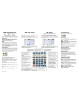
Test Connector Panel
The connectors and indicators located on the test panel (Figure 2-1) are listed and described
below.
12-15 VDC
(3A)
12 to 15 Vdc @ 3A input to power the unit or for battery charging.
WARNING
When using the AC-DC Adapter, always use a three-wire power cable connected
to a three-wire power line outlet. If power is supplied without grounding the equip
-
ment in this manner, there is a risk of receiving a severe or fatal electric shock, or
damaging the equipment.
2-1
EXTERNAL POWER LED
SERIAL
INTERFACE
EXTERNAL POWER
RF OUT/REFLECTION
BATTERY
CHARGING LED
RF DETECTOR INPUT (OPTION 5)
CW SOURCE MODULE
INTERFACE (OPTION 22)
GPS ANTENNA
Figure 2-1. S8x0D Test Connector Panel

Battery
Charging
Illuminates when the battery is being charged. The indicator automatically shuts
off when the battery is fully charged.
External
Power
Illuminates when the Site Master is being powered by the external charging unit.
Serial
Interface
RS232 DB9 interface to a COM port on a personal computer (for use with the
Anritsu Tool Box with Line Sweep Tools) or to a supported printer.
RF Out/
Reflection 50W
RF output, 50 W impedance, for reflection measurements. Maximum input is
+23 dBm at ±50 Vdc.
GPS Antenna GPS antenna connection. Do not connect anything other than the Anritsu GPS
antenna to this port.
Display Overview
Figure 2-2 illustrates some of the key information areas of the S8x0D display.
2-2
Chapter 2 Functions and Operations
TITLE BAR
DATA
POINTS
SWEEP
TIME
CALIBRATION
STATUS
MESSAGE AREA
CURRENT
MENU
Figure 2-2. S8x0D Display Overview
/