Furuno TZT16F Installation guide

Type
Installation guide
www.furuno.com
A
ll brand and product names are trademarks, registered trademarks or service marks of their respective holders.
Installation Manual
MULTI FINCTION DISPLAY
Model TZT16F
SAFETY INSTRUCTIONS ................................................................................................ i
SYSTEM CONFIGURATION ........................................................................................... ii
EQUIPMENT LISTS........................................................................................................ iii
1. MOUNTING..............................................................................................................1-1
1.1 Installation of Multi Function Display..................................................................................1-1
1.2 Installation of Transducers.................................................................................................1-6
2. WIRING....................................................................................................................2-1
2.1 Interface Connections (Rear of Unit) .................................................................................2-1
2.2 Composite Connector ........................................................................................................2-2
2.3 How to Secure and Waterproof Connections.....................................................................2-3
2.4 Power Cable ......................................................................................................................2-3
2.5 MULTI Cable......................................................................................................................2-4
2.6 DRS Radar Sensor Connections .......................................................................................2-5
2.7 Network Connector ............................................................................................................2-5
2.8 CAN bus (NMEA2000 Connector) .....................................................................................2-5
2.9 Transducer (Option)...........................................................................................................2-9
2.10 Example TZT16F System Configurations........................................................................2-10
3. HOW TO SET UP THE EQUIPMENT......................................................................3-1
3.1 How to Set Time Zone, Time Format and Language.........................................................3-3
3.2 How to Set Units of Measurement .....................................................................................3-4
3.3 Initial Setup ........................................................................................................................3-5
3.4 How to Set Up the Radar.................................................................................................3-11
3.5 How to Set Up the Sounder .............................................................................................3-14
3.6 Wireless LAN Setting .......................................................................................................3-19
3.7 Ferry Mode.......................................................................................................................3-20
PACKING LISTS ......................................................................................................... A-1
OUTLINE DRAWINGS ................................................................................................ D-1
INTERCONNECTION DIAGRAMS.............................................................................. S-1
The paper used in this manual
is elemental chlorine free.
・FURUNO Authorized Distributor/Dealer
9-52 Ashihara-cho,
Nishinomiya, 662-8580, JAPAN
A
:
FEB
2020
.
Printed in Japan
All rights reserved.
A1
:
JUN
.
18, 2020
IME-45110-A1
(
GREG
)
TZT16F
0 0 0 1 9 7 1 0 7 1 0
i
SAFETY INSTRUCTIONS
Indicates a potentially hazardous situation which, if not
avoided, could result in death or serious injury.
Indicates a potentially hazardous situation which, if not
avoided, may result in minor or moderate injury.
WARNING
CAUTION
Warning, Caution Prohibitive Action Mandatory Action
WARNING
ELECTRICAL SHOCK HAZARD
Do not open the equipment
unless totally familiar with
electrical circuits.
Only qualified personnel should
work inside the equipment.
Turn off the power at the
switchboard before beginning
the installation.
Fire or electrical shock can result
if the power is left on.
CAUTION
Be sure that the power supply is
compatible with the voltage
rating of the equipment.
Connection of an incorrect power
supply can cause fire or damage
the equipment.
Use the proper fuse.
Use of an incorrect fuse may
damage the equipment.
The front panel is made of glass.
Handle it with care.
Injury can result if the glass breaks.
Observe the following compass safe
distances to prevent interference to a
magnetic compass:
Standard
compass
TZT16F
Steering
compass
0.70 m
0.45 m
(Examples of symbols)
Model
Ground the equipment to prevent
electrical shock and mutual interference.
If your vessel is configured with
an autopilot system, install an
autopilot control unit (or emer-
gency autopilot stop button) at
each helm station, to allow you
to disable the autopilot in an
emergency.
If the autopilot cannot be disabled,
accidents may result.
ii
SYSTEM CONFIGURATION
GP-330B
FI-50/70
IF-NMEA2K2
FA-30/50
FAX-30
DC12-24V
SCX-20
SC-30/33
IF-NMEAFI
FAR-2xx7/2xx8 series
FAR-15x3/15x8 series
BBDS1, DFF series
FUSION-Link compatible devices
Autopilot
NAVpilot-300/
NAVpilot-711C
IP Camera
Remote Control Unit
MCU-005
Radar Sensor (Radome)
DRS4DL/DRS4DL+/DRS4D-NXT
Ethernet
Hub*
2
*
8
HUB-101
PoE Hub*
3
USB Hub
Remote Control Unit
MCU-002/MCU-004 or
SD Card Unit SDU-001
CCD Camera
Touch Monitor*
5
(HDMI Output)
Event Switch
External Buzzer
Power Switch
NMEA0183 Output
Junction
Box
FI-5002
Ship’s main
12 to 24V DC
Multi-beam Sonar DFF-3DMulti-beam Sonar DFF-3D
Multi Function
Display*
1
TZT16F
Multi Function
Display*
1
TZT16F
HDMI Source Devices
: Standard supply
: Optional/local supply
Radar Sensor (Open)
DRS6A X-Class/DRS12A X-Class/DRS25A X-Class
DRS6A-NXT/DRS12A-NXT DRS25A-NXT
Select an antenna type:
Radome or Open.
CCD Camera
USB Host/Devices*
4
Category of units
Antenna unit: Exposed to the weather.
Other units: Protected from the weather.
Transducer*
6
Fish Finder
Power Amplifier
DI-FFAMP
FA-40/70
or
Transducer
DC12-24V*
7
*
1
: This unit has a built-in fish finder as standard.
*
2
: A maximum of 6 units of NavNet TZtouch2/3 can be connected. NavNet TZtouch2 requires software version
7 or later. For configurations with TZT2BB included, a maximum of 4 NavNet TZtouch2/3 units can be
connected. NavNet TZtouch cannot be connected.
*
3
: Use a commercially available PoE hub. The NETGEAR GS108PE has tested as compatible.
The basic functions of the hub were verified, however the compatibility of all functions were not checked.
FURUNO cannot guarantee proper operation.
*
4
: When using a USB OTG as a USB host device, this equipment operates as a touch operation output device.
*
5
: The HDMI output resolution is fixed to 1920x1080. To use a touch monitor for operation, its output
resolution must be 1920x1080 (Aspect ratio 16:9) with HPD (Hot Plug Detection) function.
*
6
: Some transducers require connection of a 12-to-10 pin conversion cable.
*
7
: 12 VDC is only used with DRS6A-NXT. All other open array DRS sensors require 24 VDC.
*
8
: FURUNO networks allow for a maximum of three Ethernet Hub HUB-101s.
Exceeding this can cause undesirable results.
iii
EQUIPMENT LISTS
Standard supply
Optional supply
Name Type Code No. Qty Remarks
Multi Function Display TZT16F - 1
Installation Materials CP19-02500 000-037-168 1
Accessories FP26-00401 001-175-940 1
Name Type Code No. Remarks
Bracket OP19-21 001-563-960 For hanger installations.
Retrofit Kit OP19-23 001-563-980 For retrofit installations.
SD Card Unit SDU-001 000-027-148
Network HUB HUB-101 000-011-762
NMEA Data Converter IF-NMEA2K2 000-020-510
Remote Control Unit MCU-002 000-025-461
MCU-004 000-033-392
MCU-005 000-035-097
Matching Box MB-1100 000-041-353 Required for some transduc-
ers. See next page.
Junction Box FI-5002 005-008-400
Joint Box TL-CAT-012 000-167-140 For LAN network
Network (LAN) Cable MOD-Z072-020+ 001-167-880 LAN cable, cross-pair, 2 m
MOD-Z073-030+ 000-167-171
LAN cable, straight, 2 pairs,
3 m
MOD-Z072-050+ 001-167-890 LAN cable, cross-pair, 5 m
MOD-Z072-100+ 001-167-900 LAN cable, cross-pair, 10 m
MJ Cable Assy. MJ-A6SPF0016-005C 000-159-689 For FAX-30
CAN bus Cable Assy. FRU-NMEA-PMMFF-010 001-533-060 1 m
FRU-NMEA-PMMFF-020 001-533-070 2 m
FRU-NMEA-PMMFF-060 001-533-080 6 m
FRU-NMEA-PFF-010 001-507-010 1 m
FRU-NMEA-PFF-020 001-507-030 2 m
FRU-NMEA-PFF-060 001-507-040 6 m
FRU-MM1MF1MF1001 001-507-050
FRU-MM1000000001 001-507-070
FRU-MF000000001 001-507-060
External Buzzer OP03-136 000-086-443 Buzzer: PKB5-3A40
Rectifier RU-3423 000-030-443
PR-62 000-013-484 100 VAC
000-013-485 110 VAC
000-013-486 220 VAC
000-013-487 230 VAC
RU-1746B-2 000-030-439
Cable Assy. FRU-F12F12-100C 001-560-390
FRU-F12F12-200C 001-560-400
FRU-F7F7-100C 001-560-420
FRU-F7F7-200C 001-560-430
EQUIPMENT LISTS
iv
Fish Finder Power
Amplifier
DI-FFAMP 000-037-175 For 2 to 3 kW Dual-frequen-
cy CHIRP transducers
Transducer (for inter-
nal fish finder)
520-5PSD*
1
000-015-204 600 W
520-5MSD*
1
000-015-212
525-5PWD*
1
000-146-966
525STID-MSD*
1
000-011-783
525STID-PWD*
1
000-011-784
520-PLD*
1
000-023-680
525T-BSD*
1
000-023-020
525T-PWD*
1
000-023-019
525T-LTD/12*
1
000-023-679
525T-LTD/20*
1
000-023-678
SS60-SLTD/12*
1
000-023-676
SS60-SLTD/20*
1
000-023-677
526TID-HDD*
1
000-023-021 1 kW
50/200-1T *10M* *
1
000-015-170 1 kW
Matching box MB-1100
required for installation of
these transducers.
50B-6 *10M* 000-015-042
50B-6B *15M* 000-015-043
200B-5S *10M* 000-015-029
Transducer(Requires
DI-FFAMP)
28BL-6HR 000-015-081 2 kW
38BL-9HR 000-015-083
50BL-12HR 000-015-093
82B-35R 000-015-087
88B-10 *15M* 000-015-025
200B-8 *10M* 000-015-030
200B-8B *15M* 000-015-032
28BL-12HR 000-015-082 3 kW
38BL-15HR 000-015-092
50BL-24HR 000-015-094
68F-30H 000-015-073
100B-10R 000-027-438
150B-12H *15M* 000-015-074
88F-126H*2 000-015-068 5 kW
200B-12H *15M* *2 000-015-069
28F-38M *15M* *2 000-015-005 5 kW
Also requires Booster Box
BT-5-1/2.
28F-38M *30M* *2 000-015-006
50F-38 *15M* *2 000-015-009
28F-72 *15M* *2 000-015-007 10 kW
Also requires Booster Box
BT-5-1/2.
28F-72 *30M* *2 000-015-008
50F-70 *15M* *2 000-015-011
CHIRP Transducer
(for internal fish finder)
TM150M 000-035-500 300 W
B-75L 000-035-501
B-75H 000-035-502 600 W
B-175H 000-035-504 1 kW
B-175L 000-035-503
Name Type Code No. Remarks
EQUIPMENT LISTS
v
*
1
: Compatible with ACCU-FISH™, Bottom Discrimination and RezBoost™ Enhanced mode. All
other listed transducers, however, are compatible with RezBoost™ Standard mode.
*
2
: Rated power of these transducers is 5/10 kW, but the actual output power from DI-FFAMP is
3 kW.
Other compatible transducers (local supply)
The transducers (Manufactured by AIRMAR Technology Corporation) listed in the table below are
compatible with this equipment.
Single Frequency CHIRP (For internal fish finder)
Dual Frequency CHIRP (For internal fish finder)
CHIRP Transducer(for
internal fish finder)
B265LH-FJ12 000-037-609 1 kW ACCU-FISHTM func-
tion available
CM265LH-FJ12 000-037-610
TM265LH-FJ12 000-037-611
CHIRP Transduc-
er(Requires DI-
FFAMP)
PM111LHG 000-027-404 2 kW
CM599LHG 000-027-406 2 to 3 kW
CM599LM 000-027-407
Thru-Hull Pipe TRB-1100(1) 000-027-409
TRB-1000(1) 000-015-215
TRB-1100(2) 000-015-218
TFB-4000(1) 000-015-205
TFB-5000(1) 000-015-206
TWB-6000(2) 000-015-207
TFB-7000(1) 000-022-532
TFB-7000(2) 000-015-209
Booster Box BT-5-1/2 001-411-880 For 5 kW and 10 kW trans-
ducers
Extension Cable*3 C332 10M 001-464-120
*3: Use of the extension cable may cause the following problems:
• Reduced detection ability
Wrong ACCU-FISH™ information (fish length smaller than actual length, fewer fish detections, er-
ror in individual fish detection).
Wrong speed data
No TD-ID recognition
Output power Model
300 W B150M SS75L
600 W B75M B785M SS75M SS75H
1 kW B175M B175HW TM185M TM185HW B285M B285HW
Output power Model Remarks
1 kW B265LH CM265LH TM265LH ACCU-FISHTM function available
B265LM B275LHW CM265LM ACCU-FISHTM function NOT available
CM275LHW TM265LM TM275LHW
Name Type Code No. Remarks
EQUIPMENT LISTS
vi
Dual Frequency CHIRP (For DI-FFAMP)
Output power Model
2 kW PM111LH PM111LHW R109LH R109LHW R111LH
2 to 3 kW CM599LH CM599LHW R509LH R509LHW R509LM
R599LH R599LM
1-1
1. MOUNTING
1.1 Installation of Multi Function Display
The TZT16F is designed to be mounted in a console or panel, or mounted on a desk-
top.
The installer of this equipment must read and follow the descriptions in this manual.
Wrong installation or maintenance can void the warranty.
Mounting Considerations
When selecting a mounting location for TZT16F, keep the following in mind:
The temperature at the mounting location shall be between -15°C and +55°C.
The humidity at the mounting location shall be 93% or less at 40°C.
Locate the unit away from exhaust pipes and ventilators.
The mounting location should be well ventilated.
Mount the unit where shock and vibration are minimal (compliant with IEC 60945
Ed.4).
Keep the unit away from electromagnetic field generating equipment such as
motors and generators.
For maintenance and checking purposes, leave sufficient space around the unit and
leave slack in cables. Minimum recommended space is shown in the outline
drawing for the display units.
Do not mount the unit on the overhead.
A magnetic compass will be affected if the equipment is placed too close to it.
Observe the compass safe distances shown in "SAFETY INSTRUCTIONS" to
prevent disturbance to the magnetic compass.
1.1.1 How to install the multi function display
Referring to the figure below, select a flat mounting location. Read the installation in-
structions before starting. Pay particular attention to the notes; failure to follow these
instructions may cause damage to the unit.
Note: Ensure the mounting location is flat, with no indents or protrusions, to allow a
secure fit.
1. Prepare a cutout in the mounting location using the template (supplied) for the
TZT16F.
Flat
Curved Bumpy
1. MOUNTING
1-2
2. Fasten the wing bolts and the wing nuts of the flush mount fixture so that the pro-
tector for screw moves to the flush mount fixture.
Note: Slowly fasten the four wing bolts evenly with your hand. Do not use a tool
to fasten the wing bolts. A tool can be used to fasten the wing nuts; use caution
so as not to damage the wings or thread.
3. Connect all cables at the back of the TZT16F. (See section 2.1)
4. Remove the hex bolts from the flush mounting plate.
5. Attach flush mount sponges to the bezel of TZT16F.
6. Set TZT16F to the cutout made at step 1.
Wing nut
Wing bolt
Flush mount fixture
Flush mount fixture
Protector for screw
Move to the fixture
Attach mount sponge on
the highlighted area.
Peel off the release paper.
Flush mount sponge 16V (2 pcs.)Flush mount sponge 16H (2 pcs.)
Unit (Rear Side)
1. MOUNTING
1-3
7. Attach the flush mount fixture to the TZT16F with hex bolts.
8. Fasten each wing bolt (4 pcs.) so that the protector for screw touches the mount-
ing panel.
9. Fasten the wing nuts tightly.
Note: Use of excessive torque when fastening the wing bolts can cause the flush
mount fixture to tilt or warp. Check that the flush mount fixtures and wing bolts are
not tilted or warped, referring to the following examples.
Set TZT16F to the cutout.
Attach the flush mounting
plate to the TZT16F.
Attach the flush mounting
plate to the TZT16F.
Wing bolt
Wing nut
Flush mounting fixture
Protector for screw
Mounting panel
TZT unitTZT unit
Flush mount fixture is fixed at right angle. Flush mount fixture is warped, wing bolts are tilted.
1. MOUNTING
1-4
1.1.2 Retrofit Kit for TZT16F (option)
When upgrading to the TZT16F, use the retrofit kit (OP19-23).
Type: OP19-23 Code No. 001-563-980
1. Prepare a cutout in the mounting location using the template (supplied) for the
TZT16F.
2. Place the TZT16F unit face-down on a a soft, clean surface.
3. Set the F Mount Panel to the TZT16F unit, then using the hex bolts attached to
TZT16F, fix the F Mount Panel to the unit.
4. Connect necessary cable, referring to chapter 2.
5. Set the unit and F Mount Panel into the cutout as shown in the figure to the right,
then use the supplied self-tapping screws (SUS304 × 6 pcs.), fix the F Mount
Panel to the console.
Note: Be careful not to pinch the cables connected at step 4.
Note: Where the mounting location may be exposed to water (spray or splash),
apply a bead of marine sealant around the rear of the F Mount Panel, for water-
Optional kit Type Code No. Qty
F Mount Panel 16 19-034-1481 100-431-270-10 1
Self-tapping screws 5X20 SUS304 001-336-820-10 6
Hex bolt
TZT unit
TZT unit
Hex bolt
Frontmount panel
1. MOUNTING
1-5
proofing, before setting the F Mount Panel and unit into the cutout. Wipe the area
clean to remove any marine sealant residue and allow time for the marine sealant
to dry.
1.1.3 Desktop mounting (option)
Follow the appropriate procedure below to mount the TZT16F.
Use the optional kit Bracket16 (contents shown below), for mounting the TZT16F.
Type: OP19-21 Code No. 001-563-940
1. Fix the hanger by using self-tapping screws (5 × 20 SUS304, supplied). The screw
locations are indicated in the figure below.
2. Place the TZT16F face-down on a soft, clean surface, then fit the washers and
knob bolts as shown in the figure below, leaving a gap of approximately 30 mm.
The washers have a leading edge which must face the unit.
Name Type Code No. Qty
Bracket 16 OP19-21-1 001-563-960 1
Knob (N1) 19-033-1001-0 100-418-430-10 2
Washer 05-024-0123-1 100-076-101-10 2
Self-tapping screw 5X20 SUS304 000-162-608-10 4
Knob Knob
Washer Washer
Washer leading edge
1. MOUNTING
1-6
3. Set the TZT16F unit to the hanger and tighten the knob bolts.
1.2 Installation of Transducers
Note: For instructions regarding installation of network fish finder transducers, see the
respective manual.
There are three methods for installing the
transducer on the ship (thru-hull mount, in-
side the hull and transom mount) and one of
those methods is to be selected according to
the structure of the ship. The procedure
which follows below shows how to install a
small transducer (520-5PSD/5MSD) as the
representative example of installation.
1.2.1 How to mount a transducer
through the hull
Transducer mounting location
The thru-hull mount transducer provides the
best performance of all, since the transducer protrudes from the hull and the effect of
air bubbles and turbulence near the hull skin is reduced. If your boat has a keel, the
transducer should be at least 30 cm away from it.
The performance of this fish finder is directly related to the mounting location of the
transducer, especially for high-speed cruising. The installation should be planned in
advance, keeping the length of the transducer cable and the following factors in mind:
Hanger
Knob boltKnob bolt
CAUTION
Do not cover the transducer with FRP resin.
The heat generated when the resin hardens
may damage the transducer. CHIRP transduc-
ers are especially vulnerable to heat.
28
ø22
120
68
30
ø24
120
68
87
Unit: mm
520-5PSD
520-5MSD
BOW
1. MOUNTING
1-7
Air bubbles and turbulence
caused by movement of
the boat seriously degrade
the sounding capability of
the transducer. The trans-
ducer should, therefore, be
located in a position where
water flow is the smooth-
est. Noise from the propel-
lers also adversely affects
performance and the trans-
ducer should not be mount-
ed nearby. The lifting
strakes are notorious for
creating acoustic noise,
and these must be avoided
by keeping the transducer
inboard of them.
The transducer must always remain submerged, even when the boat is rolling,
pitching or up on a plane at high speed.
A practical choice would be somewhere between 1/3 and 1/2 of your boat's length
from the stern. For planing hulls, a practical location is generally rather far astern,
so that the transducer is always in water regardless of the planing attitude.
Installation procedure
1. With the boat hauled out of the water, mark the location chosen for mounting the
transducer on the bottom of the hull.
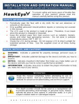
2. If the hull is not level within 15° in any direction, fairing blocks made out of teak
should be used between the transducer and hull, both inside and outside, to keep
the transducer face parallel with the water line. Fabricate the fairing block as
shown below and make the entire surface as smooth as possible to provide an
undisturbed flow of water around the transducer. The fairing block should be
smaller than the transducer itself to provide a channel to divert turbulent water
around the sides of the transducer rather than over its face.
3. Drill a hole just large enough to pass the threaded stuffing tube of the transducer
through the hull, making sure it is drilled vertically.
4. Apply a sufficient amount of high quality caulking compound to the top surface of
the transducer, around the threads of the stuffing tube and inside the mounting
hole (and fairing blocks if used) to ensure watertight mounting.
Within the wetted bottom area
Deadrise angle within 15°
Position 1/2 to 1/3 of the hull from stern.
15 to 30 cm off center line (inside first lifting strakes.)
DEEP V
HULL
HIGH SPEED
V HULL
Hole for stuffing tube
Saw along slope of hull.
Upper Half
Lower Half
BOW
1. MOUNTING
1-8
5. Mount the transducer and fairing blocks and tighten the locknut. Be sure that the
transducer is properly oriented and its working face is parallel to the waterline.
Note: Do not over-stress the stuffing tube and locknut through excessive tightening,
since the wood block will swell when the boat is placed in the water. It is suggested
that the nut be tightened lightly at installation and re-tightened several days after the
boat has been launched.
1.2.2 How to mount a transducer inside the hull
Remarks on installation
This method is useful when mounting a transducer inside the hull of FRP ship, how-
ever, it affects the ability to detect the bottom, fish and other objects.
Do the installation with the ship moored at a dock, etc. The water depth should be
6.5 to 32 feet (2 to 10 meters).
Turn off the engine.
Do not power the unit with the transducer in the air, to prevent damage to the
transducer.
Do not use this method on a double layer hull.
Before attaching the transducer to the hull, check that the site is suitable, by following
steps 1 to 3 in the installation procedure below.
Flat Hull
Deep-V Hull
Flat Washer
Rubber Washer
Fairing Block
Hull
Hull
Flat Washer
Rubber Washer
Cork Washer
NOTICE
This installation method affects the ability to detect the bottom,
fish and other objects because the ultrasound pulse is weakened
when it passes through the hull.
Therefore, refrain from this mounting method for a transducer
that supports the RezBoost™ (Enhanced Mode), ACCU-FISH™
and/or bottom discrimination display feature.
1. MOUNTING
1-9
Necessary tools
The following tools are required:
Selecting a location to install the transducer
Install the transducer on the hull plate inside of the engine room. The attenuation of
the ultrasound pulse varies with the thickness of the hull. Select a location where at-
tenuation is the lowest.
Select 2-3 locations considering the four points mentioned below.
Decide the most suitable site from the locations selected with the following proce-
dures.
1. Connect the power cable and transducer cable to the display unit.
2. Put the transducer into a water-filled plastic bag.
Press the transducer against the chosen site.
3. Tap (power switch) to turn the power on.
4. After the startup procedure completes (approx. 90
seconds), the last used display appears. Tap the
[Home] icon ( ) to show the home
screen and display mode settings. See section 3.3
for how to use the menu.
5. Scroll the menu to show [Fish Finder] in the menu, then tap [Fish Finder].
6. Scroll the [Fish Finder] menu to show the [FISH FINDER INITIAL SETUP] menu,
then tap [Fish Finder Source].
7. Confirm the available fish finder from the list of available sounders, then tap the
appropriate fish finder. For the purpose of this example, the default setting
[TZT16F] (internal sounder) is selected as the source.
8. Tap the [<] icon to return to the [Fish Finder] menu.
• Sandpaper (#100)
• Marine sealant
Water-filled plastic bag
Mount the transducer at a location 1/2 to 1/3 of the length of your boat from the
stern.
The mounting location is between 15 to 50 cm from the centerline of the hull.
Do not place the transducer over hull struts or ribs which run under the hull.
Avoid a location where the rising angle of the hull exceeds 15°, to minimize the
effect of the boat's rolling.
1/3
1/2
Centerline
Transducer mounting location
50 cm
50 cm
15 cm
15 cm
Plastic bag
Water
Hull plate
Home
1. MOUNTING
1-10
9. Scroll the [Fish Finder] menu to show the [FISH FINDER INITIAL SETUP] menu,
then tap [Transducer Setup].
10. Tap [Transducer Setup Type].
11. Tap [Model].
12. Tap the [<] icon to return to [Transducer Setup] menu.
13. Tap [Model Number], scroll the menu to show your transducer model, then tap the
transducer model number.
14. Tap the [<] icon twice to return to the [Fish Finder] menu, then scroll the [Fish Find-
er] to show the [FISH FINDER INITIAL SETUP] menu.
15. At the [Transmission Power] menu item, set the transmission power to a level of
[Max].
16. Scroll the menu to show [Fish Finder Transmit], then tap [Fish Finder Transmit].
Check if the bottom echo appears on the right side of the screen, in the display
area.
If no bottom echo appears, repeat the procedure until a suitable location is found.
17. Turn off the power of the control unit and remove the transducer from the plastic
bag and wipe the face of transducer with a cloth to remove water and any foreign
material.
Installation procedure
1. Lightly roughen the transducer face with #100 sandpaper. Also, use the sandpa-
per to roughen the inside of the hull where the transducer is to be mounted. Wipe
off any sandpaper dust from the face of the transducer.
2. Dry the face of the transducer and the hull. Coat the transducer face and mounting
location with marine sealant. Hardening begins in approx. 15 to 20 minutes so do
this step without delay.
3. Attach the transducer to the hull. Press the transducer firmly down on the hull and
gently twist it back and forth to remove any air which may be trapped in the marine
sealant.
4. Support the transducer with a piece of wood to keep it in place while the sealant
is drying. It takes 24 to 72 hours to harden completely.
Transducer
Marine sealant
Hull
Marine sealant
1. MOUNTING
1-11
5. Turn the power on and change the menu setting as shown below. See section 3.3
for how to use the menu.
1) Tap the [Home] icon to show the home screen and display mode settings.
2) Scroll the menu to show [Fish Finder] in the menu, then tap [FISH FINDER
INITIAL SETUP] menu.
3) At the [Transmission Power Mode] menu item, set the transmission power to
a level of [Max].
4) Adjust the Bottom Level and Gain Offset settings as shown in the table below.
1.2.3 How to install the transom mount transducer
The optional transom mount transducer is very commonly employed, usually on
relatively small I/O or outboard boats. Do not use this method on an inboard motor
boat because turbulence is created by the propeller ahead of the transducer.
DO NOT over-tighten screws, to prevent damage to the transducer.
Installation procedure
A suitable mounting location is at least 50 cm away from the engine and where the
water flow is smooth.
1. Drill four pilot holes for self-tapping screw (5 × 20) in the mounting location.
2. Coat the threads of the self-tapping screws (5 × 14) for the transducer with marine
sealant for waterproofing. Attach the transducer to the mounting location with the
self-tapping screws.
3. Adjust the transducer position so the
transducer faces right to the bottom.
If necessary, to improve water flow
and minimize air bubbles staying on
the transducer face, incline the trans-
ducer about 5° at the rear. This may
require a certain amount of experi-
mentation for fine tuning at high cruis-
ing speeds.
Menu Item Setting
Bottom Level HF -40
Bottom Level LF -40
Gain Offset HF 20
Gain Offset LF 20
Transom
Transom
Strake
Parallel with hull
Mount at the strake.
Less than 10°
Less than 10°
Over 10°
5x20
M5x14
Taping
1. MOUNTING
1-12
4. Tape the location shown in the figure below.
5. Fill the gap between the wedge front of
the transducer and transom with epoxy
material to eliminate any air spaces.
6. After the epoxy hardens, remove the
tape.
Transducer face inclination
If the hull is not level within 15° in any direc-
tion, install the transducer so that it protrudes from the hull, to keep the transducer face
parallel with the water line, not with the hull.
This installation method has a merit for avoiding the bubbles by diverting turbulent wa-
ter around the sides of the transducer rather than over its face. However, it may cause
damage to the transducer during trailering, launching, hauling, and storage.
Transducer preparation
Before putting your boat in water, wipe the face of the transducer thoroughly with a
liquid detergent. This will lessen the time necessary for the transducer to have good
contact with the water. Otherwise the time required for complete "saturation" will be
lengthened and performance will be reduced.
DO NOT paint the transducer. Performance will be affected.
1.2.4 How to install a triducer
DO NOT over-tighten screws, to prevent damage to the transducer.
Tools and materials required
• Scissors • Masking tape
• Safety goggles • Dust mask
• Electric drill • Screwdrivers
• Drill bit:
For bracket holes: 4 mm, #23, or 9/64"
For fiberglass hull: chamfer bit (preferred), 6 mm, or 1/4"
For transom hole: 9 mm or 3/4" (optional)
For cable clamp holes: 3 mm or 1/8"
• Straight edge • Marine sealant
• Pencil • Cable ties
Water-based anti-fouling paint (mandatory in salt water)
Bracket
Transducer
2 to 5°
Epoxy material
Hull
  • Page 1 1
  • Page 2 2
  • Page 3 3
  • Page 4 4
  • Page 5 5
  • Page 6 6
  • Page 7 7
  • Page 8 8
  • Page 9 9
  • Page 10 10
  • Page 11 11
  • Page 12 12
  • Page 13 13
  • Page 14 14
  • Page 15 15
  • Page 16 16
  • Page 17 17
  • Page 18 18
  • Page 19 19
  • Page 20 20
  • Page 21 21
  • Page 22 22
  • Page 23 23
  • Page 24 24
  • Page 25 25
  • Page 26 26
  • Page 27 27
  • Page 28 28
  • Page 29 29
  • Page 30 30
  • Page 31 31
  • Page 32 32
  • Page 33 33
  • Page 34 34
  • Page 35 35
  • Page 36 36
  • Page 37 37
  • Page 38 38
  • Page 39 39
  • Page 40 40
  • Page 41 41
  • Page 42 42
  • Page 43 43
  • Page 44 44
  • Page 45 45
  • Page 46 46
  • Page 47 47
  • Page 48 48
  • Page 49 49
  • Page 50 50
  • Page 51 51
  • Page 52 52
  • Page 53 53
  • Page 54 54
  • Page 55 55
  • Page 56 56
  • Page 57 57
  • Page 58 58
  • Page 59 59
  • Page 60 60
  • Page 61 61
  • Page 62 62
  • Page 63 63
  • Page 64 64
  • Page 65 65

Furuno TZT16F Installation guide

Type
Installation guide

Ask a question and I''ll find the answer in the document

Finding information in a document is now easier with AI