Page is loading ...

High Efficiency Solutions
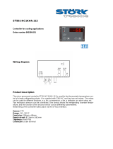
SmartCella/SmartCella 3PH
NO POWE
R
& SIGNAL
CABLES
TOGETHE
R
READ CAREFULLY IN THE TEXT!
Electronic controllers for cold rooms
User manual


3
ENG
“SmartCella manual” +0300084EN - rel. 1.2 - 28.03.2017
WARNING
CAREL bases the development of its products on decades of experience in
HVAC, on the continuous investments in technological innovations to products,
procedures and strict quality processes with in-circuit and functional testing on
100% of its products, and on the most innovative production technology available
on the market. CAREL and its subsidiaries nonetheless cannot guarantee that all
the aspects of the product and the software included with the product respond
to the requirements of the fi nal application, despite the product being developed
according to start-of-the-art techniques.
The customer (manufacturer, developer or installer of the fi nal equipment) accepts
all liability and risk relating to the confi guration of the product in order to reach
the expected results in relation to the specifi c fi nal installation and/or equipment.
CAREL may, based on specifi c agreements, act as a consultant for the positive
commissioning of the fi nal unit/application, however in no case does it accept
liability for the correct operation of the fi nal equipment/system.
The CAREL product is a state-of-the-art product, whose operation is specifi ed in the
technical documentation supplied with the product or can be downloaded, even
prior to purchase, from the website www.CAREL.com.
Each CAREL product, in relation to its advanced level of technology, requires setup
/ confi guration / programming / commissioning to be able to operate in the best
possible way for the specifi c application. The failure to complete such operations,
which are required/indicated in the user manual, may cause the fi nal product to
malfunction; CAREL accepts no liability in such cases.
Only qualifi ed personnel may install or carry out technical service on the product.
The customer must only use the product in the manner described in the
documentation relating to the product.
In addition to observing any further warnings described in this manual, the
following warnings must be heeded for all CAREL products:
• Prevent the electronic circuits from getting wet. Rain, humidity and all
types of liquids or condensate contain corrosive minerals that may damage
the electronic circuits. In any case, the product should be used or stored
in environments that comply with the temperature and humidity limits
specifi ed in the manual.
• Do not install the device in particularly hot environments. Too high
temperatures may reduce the life of electronic devices, damage them and
deform or melt the plastic parts. In any case, the product should be used
or stored in environments that comply with the temperature and humidity
limits specifi ed in the manual.
• Do not attempt to open the device in any way other than described in the
manual.
• Do not drop, hit or shake the device, as the internal circuits and mechanisms
may be irreparably damaged.
• Do not use corrosive chemicals, solvents or aggressive detergents to clean
the device.
• Do not use the product for applications other than those specifi ed in the
technical manual.
All of the above suggestions likewise apply to the controllers, serial boards,
programming keys or any other accessory in the CAREL product portfolio.
CAREL adopts a policy of continual development. Consequently, CAREL reserves
the right to make changes and improvements to any product described in this
document without prior warning.
The technical specifi cations shown in the manual may be changed without prior
warning.
The liability of CAREL in relation to its products is specifi ed in the CAREL general
contract conditions, available on the website www.CAREL.com and/or by specifi c
agreements with customers; specifi cally, to the extent where allowed by applicable
legislation, in no case will CAREL, its employees or subsidiaries be liable for any
lost earnings or sales, losses of data and information, costs of replacement
goods or services, damage to things or people, downtime or any direct, indirect,
incidental, actual, punitive, exemplary, special or consequential damage of any
kind whatsoever, whether contractual, extra-contractual or due to negligence, or
any other liabilities deriving from the installation, use or impossibility to use the
product, even if CAREL or its subsidiaries are warned of the possibility of such
damage.
DISPOSAL
INFORMATION FOR USERS ON THE CORRECT HANDLING OF WASTE
ELECTRICAL AND ELECTRONIC EQUIPMENT (WEEE)
In reference to European Union directive 2002/96/EC issued on 27 January 2003
and the related national legislation, please note that:
• WEEE cannot be disposed of as municipal waste and such waste must be
collected and disposed of separately;
• the public or private waste collection systems defi ned by local legislation must
be used. In addition, the equipment can be returned to the distributor at the
end of its working life when buying new equipment;
• the equipment may contain hazardous substances: the improper use or
incorrect disposal of such may have negative eff ects on human health and on
the environment;
• the symbol (crossed-out wheeled bin) shown on the product or on the
packaging and on the instruction sheet indicates that the equipment has
been introduced onto the market after 13 August 2005 and that it must be
disposed of separately;
• in the event of illegal disposal of electrical and electronic waste, the penalties
are specifi ed by local waste disposal legislation.
Warranty on the materials: 2 years (from the date of production, excluding
consumables).
Approval: the quality and safety of CAREL INDUSTRIES Hqs products are
guaranteed by the ISO 9001 certifi ed design and production system.
NO POWE
R
& SIGNAL
CABLES
TOGETHE
R
READ CAREFULLY IN THE TEXT!
WARNING: separate as much as possible the probe and digital input
signal cables from the cables carrying inductive loads and power cables
to avoid possible electromagnetic disturbance.
Never run power cables (including the electrical panel wiring) and signal
cables in the same conduits.


5
ENG
“SmartCella manual” +0300084EN - rel. 1.2 - 28.03.2017
Content
1. INTRODUCTION 7
1.1 Main features ...............................................................................................................7
1.2 Accessories ....................................................................................................................8
2. INSTALLATION 9
2.1 Dimensions (mm) ....................................................................................................9
2.2 Wall mounting ............................................................................................................9
2.3 Wiring diagram ........................................................................................................10
2.4 Installation ..................................................................................................................13
2.5 Programming key IROPZKEY00/A0 .............................................................13
2.6 Remote display connection.............................................................................14
2.7 Network connection ............................................................................................14
3. USER INTERFACE 15
3.1 Display ...........................................................................................................................15
3.2 Keypad ..........................................................................................................................15
3.3 Signal LEDs .................................................................................................................16
3.4 Programming ............................................................................................................16
4. COMMISSIONING 19
4.1 Confi guration............................................................................................................19
4.2 Loading the sets of parameters .....................................................................20
4.3 Preparing for operation ......................................................................................20
5. FUNCTIONS 21
5.1 Probes (analogue inputs) ..................................................................................21
5.2 Digital inputs .............................................................................................................21
5.3 Digital outputs .........................................................................................................25
6. CONTROL 26
6.1 Switching the controller On/Off ...............................................................26
6.2 Virtual probe ..............................................................................................................26
6.3 Set point.......................................................................................................................26
6.4 Pump down ...............................................................................................................27
6.5 Autostart in pump down ..................................................................................27
6.6 Continuous cycle ....................................................................................................28
6.7 Anti-sweat heater ...................................................................................................28
6.8 Light and Aux outputs ........................................................................................28
6.9 Defrost ...........................................................................................................................29
6.10 Evaporator fans ........................................................................................................31
6.11 Condenser fans ........................................................................................................32
6.12 Duty setting (par. c4) ............................................................................................32
6.13 Running time defrost (par. d10, d11) .........................................................32
7. PARAMETER TABLE 33
7.14 Variables only accessible via serial connection ...................................36
8. SIGNALS AND ALARMS 37
8.1 Signals ...........................................................................................................................37
8.2 Alarms............................................................................................................................37
8.3 Reset alarms ...............................................................................................................37
8.4 HACCP alarms and display ...............................................................................37
8.5 Alarm parameters ..................................................................................................40
8.6 HACCP alarm parameters and monitoring ............................................40
8.7 High condenser temperature alarm ..........................................................41
8.8 Frost protection alarm .........................................................................................41
8.9 Defrost ended by timeout alarm ..................................................................41
9. TECHNICAL SPECIFICATIONS 42
9.1 Technical specifi cations ......................................................................................42
9.2 SmartCella 3PH wiring diagrams ..................................................................44
9.3 Connections for pump down operation managed
by Smartcella ............................................................................................................48
10. APPENDIX 1: VPM (VISUAL PARAMETER
MANAGER) 50
10.1 Installation ................................................................................................................50
10.2 Opening the program .........................................................................................50
10.3 Computer - key connection ............................................................................50
10.4 Programming ............................................................................................................50
10.5 Modify a parameter ..............................................................................................51
10.6 Add a set of parameters .....................................................................................51
10.7 Write parameters ....................................................................................................51
11. APPENDIX 2: ADVANCED FUNCTIONS 52
11.8 Variation of the defrost interval .....................................................................52
11.9 Defrost with 2 evaporators ...............................................................................53
11.10 Second compressor with rotation ...............................................................53


7
ENG
“SmartCella manual” +0300084EN - rel. 1.2 - 28.03.2017
1. INTRODUCTION
SmartCella comprises a series of microprocessor-based parametric
electronic controllers, with LED display, designed to control single-phase
cold rooms with single-phase or three-phase loads.
This controller is especially suitable for applications requiring high load
switching power, functions and control with direct access from the
keypad, high IP ingress protection and compact dimensions. In terms
of reliability, all the controllers are fi tted with an electronic device
(watchdog) that prevents the microprocessor from losing control, even
with high levels of electromagnetic disturbance.
SmartCella is made using the most advanced SMD technology, and
electrical testing of all the components fi tted guarantees high quality
standards.
In summary:
• up to 4 relay outputs on the more complete models: compressor, fan,
defrost, AUX or contactor (three-phase);
• vertical or horizontal wall mounting, depending on the model;
• buttons fl ush with the front panel, to ensure high ingress protection
(IP65) and safety during operation and cleaning;
• bright 3 digit display, with decimal point and icons to denote operating
status;
• immunity to brief power interruptions: if the controller detects that
voltage drops below a certain threshold, the display is temporarily
switched off and the controller continues working normally;
• keypad with 4 buttons
• defrosts can be activated from the keypad, digital input, supervisor;
• management of various types of defrost, on one or two evaporators:
natural (stopping the compressor), heater, hot gas;
• advanced defrost functions;
• automatic recognition of the network protocol: Carel or Modbus®;
• parameter selection simplifi ed by diff erent icons according to the
category;
• temperature control with virtual control probe and set point variation
at night;
• digital inputs to activate alarms, enable or activate defrosts, door /
curtain switch, auxiliary output, on/off , etc.;
• control of 1 compressor with two steps, or two compressors, including
rotation;
• keypad protection: the functions of the individual buttons can be
disabled to prevent unwanted tampering;
• cold room light management;
• VPM program (Visual Parameter Manager), running on a personal
computer, used to update the parameters and test the controller;
• alarm signal buzzer;
• HACCP functions: temperature monitoring and recording in the event
of high temperature alarms during operation and after blackouts;
• RS485 serial network connection to remote supervisor and
telemaintenance systems.
The models diff er in terms of:
• management of single-phase and/or three-phase loads
• the type of power supply: transformer 230V~, switching 115/230 V~;
• the number of relay outputs;
• vertical or horizontal installation.
Available accessories include:
• serial interface card (P/N IROPZ48500) for connection to the RS485
network;
• programming key (P/N IROPZKEY**) for reading (upload) and writing
(download) the control parameters;
• display interface (P/N IROPZDSP00) for remote display connection.
1.1 Main features
SmartCella is designed to off er maximum installation fl exibility. In
addition to the control probe, further four probes can be confi gured,
as product probe (display only), condenser, frost protection and defrost
probe. Using the advanced defrost functions, if the conditions are
right, subsequent defrosts can be postponed or skipped. The digital
outputs (relays) can control the solenoid valve or compressor, a second
compressor, the evaporator or condenser fans, defrosts, lights and alarms.
The digital inputs can be used for the door switch and light management,
the curtain switch to change over to night-time operation, to enable
and start defrosts, to switch the controller on/off and to activate of the
auxiliary output. Finally, the controller can also be used as simple ON/OFF
thermostat, for heating applications.
Example of a cold room
Fig. 1.a
Single-phase version part numbers
P/N Description
WE00S1EN00 1 relay: compressor (16 A), 230 Vac, 180° screw terminals
WE00C2HN00 4 relays: compressor (2 HP) , defrost (16 A), evaporator fans
(8 A), AUX (8 A), 115/230 Vac, 180° screw terminals
WE00C2HM00 4 relays: compressor (2 HP) , defrost (16 A), evaporator
fans (8 A), AUX (8 A), 115/230 Vac, 180° screw terminals +
IROPZSER30 serial card
WE00C2HC00 4 relays: compressor (2 HP) , defrost (16 A), evaporator fans
(8 A), AUX (8 A), 115/230 Vac, 180° screw terminals + RTC
WE00C3HN00 4 relays: compressor (2 HP) , defrost (16 A), evaporator fans
(8 A), AUX (8 A), 115/230 Vac, 180° screw terminals + 3 HP
relay
WE00C2HN0H 4 relays: compressor (2 HP) , defrost (16 A), evaporator
fans (8 A), AUX (8 A), 115/230 Vac, 180° screw terminals,
horizontal installation
WE00S1ET00 1 relay: compressor (16 A), 230 Vac, 180° screw terminals +
I/O switch and wiring
WE00C2HT00 4 relays: compressor (2 HP) , defrost (16 A), evaporator fans
(8 A), AUX (8 A), 115/230 Vac, 180° screw terminals + I/O
switch and wiring
WE00S1EN0A 1 relay: compressor (16 A), 230 Vac, 180° screw terminals,
assembled with Ultra Power module
WE00C2HN0A 4 relays: compressor (2 HP) , defrost (16 A), evaporator
fans (8 A), AUX (8 A), 115/230 Vac, 180° screw terminals,
assembled with Ultra Power module
Tab. 1.a
Three-phase version part numbers
P/N Description
WP00B14A10 SmartCella 3PH 5.5HP 1.6-2.5A motor protector 3PH 6kW
defrost 1PH 500W evaporator fans 1PH 800W condenser
fans 1PH 800W light
WP00B24A10 Smartcella 3PH 5.5HP 2.5-4A motor protector 3PH 6kW
defrost 1PH 500W evaporator fans 1PH 800W condenser
fans 1PH 800W light
WP00B34A10 Smartcella 3PH 5.5HP 4-6.3A motor protector 3PH 6kW
defrost 1PH 500W evaporator fans 1PH 800W condenser
fans 1PH 800W light
WP00B44A10 Smartcella 3PH 5.5HP 6.3-10A motor protector 3PH 6kW
defrost 1PH 500W evaporator fans 1PH 800W condenser
fans 1PH 800W light

8
ENG
“SmartCella manual” +0300084EN - rel. 1.2 - 28.03.2017
P/N Description
WP00B47B20 Smartcella 3PH 7.5HP 6.3-10A motor protector 3PH 9kW
defrost 3PH 2kW evaporator fans 1PH 800W condenser fans
1PH 800W light
WP00B57B20 Smartcella 3PH 7.5HP 10-16A motor protector 3PH 9kW
defrost 3PH 2kW evaporator fans 1PH 800W condenser fans
1PH 800W light
Tab. 1.b
1.2 Accessories
IROPZKEY00/A0 programming key
The IROPZKEY00 and IROPZKEY00A0 (powered) programming keys
can be used with SmartCella. Visual Parameter Manager (VPM) allows
up to 7 diff erent confi gurations (sets) of parameters to be loaded
onto the controller (the controller operating parameters plus 6 sets of
customizable parameters). The read/write operations are carried out with
the controller off .
IROPZKEY00 IROPZKEYA0
Fig. 1.b Fig. 1.c
Connection cable (P/N PSTCON0*B0)
Three-wire cable to connect the controller to the tLAN interface card (P/N
IROPZDSP00). Available in diff erent lengths: 1.5; 3; 5 m.
Fig. 1.d
Remote display (P/N IREVXGD000)
The remote display (for model with switching power supply) can be used
to display one of the system variables.
Fig. 1.e
RS485 serial interface (P/N IROPZ48500 and IROPZ485S0)
Plugged directly into the programming key connector, this provides
connection to the PlantVisor supervisory system. The accessory has been
designed as a plug-in addition to the controller and consequently can
be installed following installation if needed. Model IROPZ485S0 features
a microprocessor and can automatically recognize the TxRx+ and TxRx
signals (reverse connection).
Fig. 1.f
RS485 serial board (P/N IROPZSER30)
The IROPZSER30 board is used to connect SmartCella via the RS485
network serial to supervisory system (using the removable terminal
supplied), as well as direct connection of the instrument to the repeater
display using a PSTCON**B00 cable.
Fig. 1.g
VPM programming tool (Visual Parameter Manager)
The program can be downloaded from http://ksa.carel.com. The tool
runs on a computer and is used to set up the controller, change the
parameter settings and update the fi rmware. The USB/I2C converter P/N
IROPZPRG00 is required.
Fig. 1.h
USB/I2C converter and cable (P/N IROPZPRG00)
Converter used to connect a personal computer to an IROPZKEY00/
A0 programming key, and consequently use the VPM program
(Visual Parameter Manager) to read, set and write the parameters. The
programming key can then be used to program the controllers or read
the controller parameters, and for example copy a confi guration from
one controller to the others.
Fig. 1.i

9
ENG
“SmartCella manual” +0300084EN - rel. 1.2 - 28.03.2017
2. INSTALLATION
2.1 Dimensions (mm)
Single-phase version
260
47,5
47,5
30
128 101
290
87,5
107,5
Ø32
103
Fig. 2.a
Three-phase version
Fig. 2.b
Drilling template
Fig. 2.c
2.2 Wall mounting
Single-phase version
2
1
1
2
1. Remove the faceplates (1 and 2) and unscrew the screws to open the
control
2. Release fl at connector to remove frontal panel
3. a. Mounting with DIN rail: Fix the DIN rail on the wall and insert the
controller. Mark the positions of the 2 bottom holes corresponding
to drilling template and extract the control. Drill the 2 holes (Ø 4,5
mm), insert again the control and fi x the 2 bottom screws
3. b. Mounting without DIN rail: Mark the positions of the 4 holes
corresponding to drilling template, drill the holes (Ø 4,5 mm) and fi x
control to wall with 4 screws
4. Complete the wiring of the cables and the necessary components
5. Insert fl at connector and frontal panel box to electronic board. Close the
front panel fi xing the 4 supplied screws corresponding to the holes
Three-phase version
1. With reference to the drilling template, drill the four fastening holes
in the wall:
• Unscrew the six fastening screws on the front panel
• Remove the front panel
• Fix the panel to the wall using screws of suitable length, based on
the thickness of the wall
2. Connect the power cables, the load power cables, the probes and
the remaining inputs/outputs to the terminal block on the panel, as
shown in the wiring diagram (see page 10/11)
3. Before starting installation, the motor protector should be calibrated
based on eff ective compressor power consumption, with reference
to the compressor’s rated data

10
ENG
“SmartCella manual” +0300084EN - rel. 1.2 - 28.03.2017
4. Arm the circuit breakers and the motor protector
5. Close the front panel using the six screws
6. Power the panel on
7. Arm the main switch (yellow/red)
Warning
• separate the power cables (power supply, loads) from the signal cables
(probes, digital inputs) and the serial cable
• use cables that are suitably sized for the current they carry
• connect the terminal marked PE to the mains power supply earth
• after having powered the three-phase expansion, check correct
current draw of the various loads
2.3 Wiring diagram
Single-phase version
WE00SxExxx
6 71 2
21 20 19
L
N
8 9 10 11 12
PROBES DIDI DI
12 2 3
1
R1
serial interface
230 V~
25mA~ max
POWER
SUPPLY
-10T45°C
IP 65
Fig. 2.d
WE00CxHxxx
5
R4
6 7
LN
1 2
24 23 22 21 20 19 15 14 13
L
N
8 9 10 11 12
PROBES DIDI DI
12 2 3
1
R1 R2 R3
serial interface
3 4
115…230 V~
50mA~ max
POWER
SUPPLY
-10T50°C
IP 65
Fig. 2.e
Three-phase version
Layouts and components
(WP00B34A10, WP00B24A10, WP00B14A10)
Fig. 2.f
WP00B57B20, WP00B47B20, WP00B44A10
Fig. 2.g

11
ENG
“SmartCella manual” +0300084EN - rel. 1.2 - 28.03.2017
Code Description
AP1 Smartcella
HL1 Power light
HL2 Evaporator light
HL3 Compressor light
HL4 Alarm light
HL5 Defrost light
KM1 Evaporator fan contactor
KM2 Compressor contactor
KM3 Defrost heater contactor
KR1 Alarm relay
QF1 Evaporator/condenser fan/defrost heater circuit breaker
QF2 Auxiliary circuit breaker
QM1 Compressor motor protector
QS1 Main disconnect switch
XA1 Auxiliary terminal block
XP1 Power terminal block
Terminal block
WP00B44A10, WP00B34A10, WP00B24A10, WP00B14A10
EVAPORATOR FAN
CONDENSER FAN
HEATERS
CARTER HEATER
COMPRESSOR
POWER INPUT
PRESSURE SWITCH LP
VALVE
THERMAL FAN
SAFETY THERMOSTAT
INTERNAL LIGHTS
AMBIENT PROBE
DEFROST PROBE
MICRO SWITCH
PRESSUR SWITCH HP/LP
COMPRESSOR KRIWAN
POWER SUPPLYKRIWAN
Terminal block XP1 Terminal block XA1
Fig. 2.h
Terminal block Number Description Type
XP1 1
Evaporator fan Output
2
3
Condenser fan Output
8
4
Defrost heaters Output
5
6
7
9
Crankcase heater Output
10
11
Compressor Output12
13
L1
Power supply input Input
L2
L3
N
Tab. 2.c
Terminal block Number Description Type
XA1 101
LP pressure switch Input
102
104
Solenoid valve Output
105
106
Fan thermal protector Input
107
108
Safety thermostat Input
109
110
Inside lights Output
111
112
Room probe Input
114
113
Defrost probe Input
114
115
Door microswitch Input
116
117
HP/LP pressure switch (*)
Input
118
119
Compressor Kriwan (*)
Input
120
121
Kriwan power supply Output
122
Tab. 2.d
(*) Warning: if input 117-118 and/or 119-120 are not connected,
the control will show an “IA“ alarm.
Terminal block XP1
Terminal block XA1

12
ENG
“SmartCella manual” +0300084EN - rel. 1.2 - 28.03.2017
Code WP00B57B20, WP00B47B20
EVAPORATOR FAN
CONDENSER FAN
HEATERS
CARTER HEATER
COMPRESSOR
POWER INPUT
PRESSURE SWITCH LP
VALVE
THERMAL FAN
SAFETY THERMOSTAT
INTERNAL LIGHTS
AMBIENT PROBE
DEFROST PROBE
MICRO SWITCH
PRESSUR SWITCH HP/LP
COMPRESSOR KRIWAN
POWER SUPPLYKRIWAN
Terminal block XP1 Terminal block XA1
Fig. 2.i
Terminal block Number Description Type
XP1 1
Evaporator fan Output2
3
4
Condenser fan Output
10
5
Defrost heaters Output
6
7
8
11
Crankcase heater Output
12
13
Compressor Output14
15
L1
Power supply input Input
L2
L3
N
Tab. 2.e
Terminal block Number Description Type
XA1 101
LP pressure switch Input
102
104
Valve Output
105
106
Fan thermal protector Input
107
108
Safety thermostat Input
109
110
Inside lights Output
111
112
Room probe Input
114
113
Defrost probe Input
114
115
Door microswitch Input
116
117
HP/LP pressure switch (*)
Input
118
119
Compressor Kriwan (*)
Input
120
121
Kriwan power supply Output
122
Tab. 2.f
(*) Warning: if input 117-118 and/or 119-120 are not connected,
the control will show an “IA“ alarm.

13
ENG
“SmartCella manual” +0300084EN - rel. 1.2 - 28.03.2017
2.4 Installation
To install the controller, proceed as follows, with reference to the wiring
diagrams shown in the previous paragraphs:
1. connect the probes and power supply: the probes can be installed up
to a maximum distance of 10 m from the controller, using shielded
cables with a minimum cross-section of 1 mm². To improve immunity
to disturbance, use probes with shielded cables (connect only one end
of the shield to the earth on the electrical panel);
2. program the controller: as shown in the chapters “Commissioning” and
“User interface”;
3. connect the actuators: the actuators should only be connected after
having programmed the controller. Carefully check the maximum
capacities of the relays or three-phase contactors, as indicated in the
“technical specifi cations”;
4. serial network connection: all controllers are fi tted with a serial
connector for connection to the supervisor network via the serial
interface (IROPZ485*0 or serial board IROPZSER30). The secondary
of the transformers that supply the controllers must not be earthed.
If connection to a transformer with earthed secondary winding is
required, an insulating transformer must be installed in between.
Important: a separate transformer must be used for each controller,
- NEVER connect multiple controllers to the same transformer.
Warnings: avoid installing the controller in environments with the
following characteristics:
• relative humidity greater than 90% non-condensing;
• strong vibrations or knocks;
• exposure to continuous water sprays;
• exposure to aggressive and polluting atmospheric agents (e.g.: sulphur
and ammonia gases, saline mist, smoke) which may cause corrosion
and/or oxidation;
• strong magnetic and/or radio frequency interference (for example ,
near transmitting antennae);
• exposure to direct sunlight and the elements in general.
The following warnings must be observed when connecting the
controllers:
• incorrect connection of the power supply may seriously damage the
controller;
• use cable ends suitable for the corresponding terminals. Loosen each
screw and insert the cable ends, then tighten the screws and gently
pull the cables to check their tightness. When tightening the screws,
do not use automatic screwdrivers, rather adjust tool tightening
torque to less than 0.5Nm;
• separate as much as possible (by at least 3 cm) the probe signal and
digital input cables from inductive loads and power cables, to avoid
any electromagnetic disturbance. Never lay power cables and probe
cables in the same cable conduits (including those for the electrical
panels). Do not install the probe cables in the immediate vicinity of
power devices (contactors, circuit breakers or the like). Reduce the
length of the sensor cables as much as possible, and avoid spirals
around power devices;
• only use IP67 guaranteed probes as end defrost probes; place the
probes with the vertical bulb upwards, so as to facilitate drainage
of any condensate. Remember that thermistor temperature probes
(NTC) have no polarity, so the order the ends are connected in is not
important.
Cleaning the controller
When cleaning the controller do not use ethanol, hydrocarbons (petrol),
ammonia and by-products. Use neutral detergents and water.
2.5 Programming key IROPZKEY00/A0
The programming key can load up to 7 diff erent parameter confi gurations
onto the controller (the controller operating parameters plus 6 sets
of customisable default parameters). The keys are plugged into the
connector (4 pin AMP) available on the controllers. All the operations can
be performed with the controller off .
Fig. 2.j
The functions are selected by setting the two dipswitches, accessible by
removing the battery cover.
UPLOAD DOWNLOAD EXTENDED DOWNLOAD
• load the parameters from a controller onto the key (UPLOAD);
• copy from the key to a controller (DOWNLOAD);
• extended copy from the key to a controller (EXTENDED DOWNLOAD).
Important: The parameters can only be copied between
controllers with the same part number. The UPLOAD operation can,
however, always be performed.
Copying and downloading the parameters
The following operations are used for the UPLOAD and/or DOWNLOAD
functions, simply by changing the settings of the dipswitches on the key:
1. open the rear cover on the key and position the 2 dipswitches according
to the desired operation;
2. close the rear cover on the key and plug the key into the connector on
the controller;
3. press the button and check the LED: red for a few seconds, then green,
indicates that the operation was completed correctly. Other signals
or the fl ashing of the LED indicates that problems have occurred: see
the table below;
4. at the end of the operation, release the button, after a few seconds the
LED goes off ;
5. remove the key from the controller.
LED signal Error Meaning and solution
Red LED
fl ashing
Batteries discharged at
start copy
The batteries are discharged,
the copy operation cannot be
performed. Replace the batteries.
Green LED
fl ashing
Batteries discharged
during copy or at end
of copy
During the copy operation or
at the end of the operation the
battery level is low. Replace the
batteries and repeat the operation.
Red/green
LEDs fl ashing
(orange signal)
Controller not
compatible
The parameter set-up cannot be
copied as the connected controller
model is not compatible. This error
only occurs for the DOWNLOAD
function; check the controller
P/N and run the copy only for
compatible models.
Red and green
LEDs on
Error in data being
copied
Error in the data being copied.
The EEPROM on the controller
is corrupted, therefore the data
cannot be copied to/from the key.

14
ENG
“SmartCella manual” +0300084EN - rel. 1.2 - 28.03.2017
Red LED on
steady
Data transfer error The copy operation was not
completed due to a serious error
when transferring or copying the
data. Repeat the operation, if the
problem persists check the key
connections.
LEDs off Batteries disconnected Check the batteries.
Tab. 2.g
Note: the DOWNLOAD operation (normal or extended) is possible
even if the operating and control parameters are incorrect; in this case,
they will be recovered from the key. Be careful when recovering the unit
parameters from a key, as these determine the low-level operation of the
controller (unit model, type of interface, assignment of logical relay to
physical relay, brightness of the display, level of modulation of the relay
control signal …). The unit parameters from the original model must
therefore be restored to ensure correct operation of the controller.
2.6 Remote display connection
To connect the remote display, use the dedicated cable (P/N PSTCON0*B0)
and serial card (P/N IROPZSER30). See the following diagram.
Also set a value >0 for parameter /tE, to display the reading on the remote
display.
Par. Description Def Min Max UOM
/tE Reading on remote display 0 6 6 -
0 Not fi tted 4 Probe 3
1 Virtual probe 5 Probe 4
2 Probe 1 6 Reserved
3 Probe 2
Tab. 2.a
2.7 Network connection
Warnings:
• As serial converter, both IROPZSER30 and IROPZ485x0 can be used;
• the RS485 converter is sensitive to electrostatic discharges and
therefore must be handled with extreme care;
• check the documents on the serial interface for connection instructions,
so as to avoid damaging the controller;
• fasten the converter properly so as to prevent disconnection;
• complete the wiring without power connected;
• keep the serial interface cables separate from the power cables (relay
outputs and power supply).
The RS485 converter is used to connect SmartCella to the supervisor
network for the complete management and monitoring of the connected
controllers. The system allows a maximum of 207 units, with a maximum
length of 1000 m. Connection requires the standard accessories (RS485-
USB converter, CAREL P/N CVSTDUMOR0) and a 120 Ω terminating resistor
to be installed on the terminals of the last connected controller. Connect
the RS485 converter to the controllers and make the connections as
shown in the fi gure. To assign the serial address, see parameter H0. See
the instruction sheets on the converters for further information.
Note: SmartCella can communicate with both Carel and Modbus
protocols with auto-recognition
SmartCella
SmartCella
Fig. 2.k

15
ENG
“SmartCella manual” +0300084EN - rel. 1.2 - 28.03.2017
3. USER INTERFACE
The front panel contains the display and the keypad, made up of 4
buttons that, when pressed alone or combined with other buttons, are
used to program the controller. The optional remote display is used to
display the temperature measured by a second probe.
3.1 Display
The user terminal display shows temperature in range -50 to +150°C.The
temperature is displayed with resolution to the tenths between –19.9
and + 19.9 °C. In the event of alarms, the value of the probe is displayed
alternating with the codes of the active alarms. During programming,
the terminal shows the codes and values of the parameters. The remote
display IREVXGD000 shows the temperature with resolution to the tenths
between -9.9°C and19.9°C.
Icon Function Normal operation Start-up Notes
ON OFF Flashing
Compressor On Off Awaiting activation Flashes when activation is delayed or
inhibited by protection times
Fan On Off Awaiting activation Flashes when activation is delayed by
protection times or other procedures in
progress
Defrost Active - Awaiting Flashes when activation is delayed by
protection times or other procedures in
progress
AUX output AUX output 1 or 2 active - Anti-sweat heater function active
Alarm On if delayed alarm from digital
input
- Alarms during normal operation
(e.g. high/low temperature alarm)
or in the event of malfunctions
(on together with the spanner
icon)
Light Auxiliary output (1 and/or 2)
confi gured as light active
- Anti-sweat heater function active
Service Malfunctions, e.g. EEPROM errors
or faulty probes
Continuous
cycle
Continuous cycle function active - Function called Flashes when activation is delayed or
inhibited by protection times
HACCP
function enabled (HA and/or HF) function enabled (HA
and/or HF)
function not enabled, HACCP
alarm saved
CLOCK
function activated function not activated function request
ON if RTC featured
Tab. 3.a
3.2 Keypad
Button Normal function Start-up
Pressing the button alone Pressing together with other buttons
PRG/MUTE
if pressed for more than 3 s accesses the menu for setting the
password to access the type “F” (frequent) parameters or “C”
(Confi guration)
in the event of alarm: silences the audible alarm (buzzer) and disables
the alarm relay
PRG+ON-OFF/UP: if pressed together for
more than 3 s reset any alarm with manual
reset
if pressed for more than 5 s
at start-up, starts the default
parameter setting
ON-OFF/UP
if pressed for more than 3 s disables the regulation / if pressed for
more than 1 s, enables the regulation
during the parameters modifi cation increase the value displayed
move towards the next parameter
ON-OFF/UP+AUX/DOWN: if pressed together for more than 3 s enable/
disable the continuous cycle operation
ON- OFF/UP+ SET/DEF: if pressed together for more than 3 s display the
temperature read by the defrost probe no 1
ON-OFF/UP+ PRG/MUTE: if pressed together for more than 3 s reset any
alarm with manual reset
AUX/DOWN
if pressed for more than 1 s, enables/disables the auxiliary output
during the parameters modifi cation decrease the value displayed or
move towards the previous paramenter
AUX/DOWN + ON-OFF/UP: if pressed together for more than 3 s enable/
disable the continuous cycle operation
AUX/DOWN + SET/DEF: if pressed together for more than 1 second, displays
a submenu used to access the parameters relating to HACCP alarms (HA,
HAn, HF, HFn, if available)
SET/DEF
if pressed for more than 1 s, enables/displays and/or set the set point
if pressed for more than 5 s, enables a manual defrost
SET/DEF+ ON-OFF/UP: if pressed together for more than 3 s display the
temperature read by the defrost probe no 1
SET/DEF+ ON-OFF/UP: if pressed together for more than 3 seconds, displays
the temperature read by defrost probe 1
Tab. 3.b

16
ENG
“SmartCella manual” +0300084EN - rel. 1.2 - 28.03.2017
3.3 Signal LEDs
Icon Colour Function Status Notes
ON OFF
Green POWER Auxiliary circuit powered Auxiliary circuit not powered LED on depending on the status (ON) of circuit
breaker QF2 and disconnect switch QS1
Yellow COMPRESSOR Power available at compressor
power terminals
No power at compressor power
terminals
LED on depending on the status (ON) of motor
protector QM1 and whether power is available
Yellow EVAPORATOR
FAN
Power available at evaporator fan
power terminals
No power at evaporator fan
power terminals
LED on depending on the status (ON) of circuit
breaker QF1 and whether power is available
Yellow DEFROST Power available at defrost power
terminals
No power at defrost power
terminals
LED on depending on the status (ON) of circuit
breaker QF1 and whether power is available
Red ALARM Alarm activated Normal operation LED on depending on: activation of circuit
breaker QF1 and/or motor protector QM1
and/or alarm input (high pressure switch or
compressor Kriwan)
Tab. 3.c
Note: the status of the LED (On/Off ) obviously depends on the
operating logic of the panel (e.g. if the temperature reaches the set point,
the compressor and the corresponding LED will be switched off by the
electronic controller, without generating alarms)
3.4 Programming
The operating parameters can be modifi ed using the front keypad. Access
diff ers depending on the type: set point, frequently-used parameters (F)
and confi guration parameters (C). The type of parameter is specifi ed in the
table of parameters. Access to the confi guration parameters is protected
by a password for the confi guration parameters that prevents unwanted
modifi cations or access by unauthorised persons. The password can be
used to access and set all the control parameters.
3.4.1 Setting the set point
How to set the set point (desired temperature value)
Step Action E ect Meaning
1
Press for 1
second
After 1 second the display will
show the current set point
This the currently
active control set
point
2
Press
or
The value on the display will
increase or decrease
Set the desired
value
3
Press
The controller will show the
temp.read by the probes again
The set point is
modifi ed and
saved
Tab. 3.d
Another way of changing the set point is to set parameter “St” (see the
tables below)
3.4.2 Setting type “F” and “C” parameters
Step Action E ect Meaning
1
Press
for 3
seconds
After 3 seconds the
display will show the 1st
parameter, “0” (Password)
Access to type “F”
parameters is direct
without password
2
Press
or
The value on the display
will increase or decrease.
Enter the password
“22” to access the
type “C” parameters
or whatever diff erent
value for the type “F”
parameters.
3
Press
The display will show “St”
(Setpoint)
This is the current value
of the Setpoint
4
Press
or
If the password set is 22
the display will scroll the
list of type “C” parameters
(CONFIGURATION)
otherwise the list of type “F”
parameters (FREQUENT)
Set the desired value
5
Press
The display will show the
parameter name
This is the current value
of the parameter
6
Press
or
The value on the display
will increase or decrease
Set the desired value
Step Action E ect Meaning
7
Press
The display will show the
parameter name again
IMPORTANT:
parameters not yet
saved
8 Repeat steps
2, 3, 4 & 5 for
all parameters
required
9
Press
for 5 seconds
The controller will display
the temperature read by
the probes again
IMPORTANT: only now
have all the parameters
been updated
Tab. 3.e
For both types of access (type “F” and type “C”) there is a timeout (no
button on the keypad pressed for 1 min), the procedure is ended without
saving the parameter.
3.4.3 Parameter categories
• To move from the parameters in one category to another, when
displaying the parameter code, press Prg to show the category and UP
and DOWN to move from one category to another;
• if no button is pressed for 10s, the display starts fl ashing, and after 1
minute automatically returns to the standard display;
• to increase the scrolling speed, press and hold the UP/DOWN button
for at least 5 seconds;
• all the changes made to the parameters, temporarily stored in the
RAM, can be cancelled, by not pressing any button for 60 seconds, thus
returning to the standard display.
Parameter categories
Category Text Icon Category Text Icon
Probes Pro
Alarms ALM
Control CtL
Fan FAn
Compressor CMP
Confi guration CnF
Defrost dEF
HACCP HcP
Clock rtc
Tab. 3.f

17
ENG
“SmartCella manual” +0300084EN - rel. 1.2 - 28.03.2017
Example 1: setting the current time/date (for models with RTC))
1. Access the type C parameters as described in the corresponding
paragraph;
2. Press UP/DOWN and select the parent parameter tc, or press the PRG
button to select the “rtc” parameter category and then parameter tc;
3. Press Set: parameter y is displayed following by two digits that
indicate the current year;
4. Press Set and set the value of the current year (e.g.: 17=2017), press
Set again to confi rm;
5. Press UP to select the next parameter - month, and repeat steps 3
and 4 for the following parameters:
6. M=month, d=day of the month, u=day of the week h=hours,
m=minutes;
7. To return to the list of main parameters press Prg/mute and then
set parameters ton and toF (see the following paragraph), or
alternatively:
8. To save the settings, press Prg/mute for 5 seconds and exit the
parameter setting procedure.
3.4.4 Setting the default parameters
To set the parameters to the default values:
• Power down the controller;
• Press Prg/mute;
• Power up the controller holding the Prg/mute button, until the
message “Std” or “Bn0“ (on SmartCella 3PH) are shown on the display,
after 5 s.
Note: this will cancel any changes made and restore the original
values set by the manufacturer, i.e. the default values shown in the
parameter table.
3.4.5 Defrost
To activate a defrost, the defrost probe must measure a temperature less
than the end defrost temperature (par. dP1).
ACTIVATION: Press SET for 5 seconds:
After 5 seconds, the display shows the start defrost signal (dFb) for 3 s.
The controller enters defrost mode, with the corresponding icon shown
on the display, together with the message “dEF” if set accordingly by
parameter d6. The defrost relay is also activated.
Par. Description Def Min Max UoM
d6 Terminal display during defrost
0 = Temperature alternating with dEF
1 = Display disabled
2 = dEF
102-
Tab. 3.g
DEACTIVATION: Press SET for 5 seconds :
After 5 seconds, the display shows the end defrost signal (dFE). The
controller exits defrost mode, returning to the standard display.
3.4.6 On/O
To switch the controller off from the keypad:
• press On-Off for 3 seconds.
The display shows the text Off fl ashing for 3 seconds, and then on steady.
Finally, the text Off alternates with the standard display. Any active output
relays are deactivated.
To switch the controller on from the keypad:
• press On-Off for 1 s.
The display shows the text On for 1 s and then returns to the standard
display. Any output relays are activated again.
3.4.7 Continuous cycle
For the explanation of the continuous cycle function, see chapter 6.
To activate the continuous cycle, the value of parameter cc must be >0.
ACTIVATION: Press ON/OFF + AUX for 5 seconds
+
The message “cc” fl ashes on the display for 3 seconds, and subsequently,
if the conditions are suitable, the controller shows the start continuous
cycle message “ccb” and the corresponding icon on the display.
DEACTIVATION: Press ON/OFF + AUX for 5 seconds
+ :
The message “cc” fl ashes on the display for 3 seconds, and subsequently
the controller shows the end continuous cycle message, “ccE”.
3.4.8 Display defrost probe
To display the value measured by the defrost probe:
• press Set and UP together for 3 s;
• the code of parameter d/1 is displayed fl ashing;
• continue holding the buttons until the value measured by the defrost
probe is displayed;
• release the buttons;
• the standard display is shown again after 10 s.
3.4.9 Auxiliary/light output activation
To activate the auxiliary (H1 = 2) and/or light output (H1 = 3) from the
keypad:
• press AUX;
• the message AUX fl ashes on the display for 1 s:
• press and hold until activating the output and the corresponding icon
on the display, which then shows the standard display.
3.4.10 Probe calibration
Parameters /c1 to /c4 are used are used to calibrate the fi rst, second, third
and fourth temperature probe respectively. Access the parameters and
then set the required values. When pressing Set, after having entered the
value, the display does not show the parameter, but rather immediately
shows the new value of the probe reading being calibrated. This means
the result of the setting can be checked immediately and any adjustments
made as a consequence. Finally, press Prg for 5 seconds to save the value
of the parameter.
3.4.11 HACCP menu
The controller must be fi tted with RTC (real time clock).
To enter the HACCP menu:
• press the + buttons together for 1 s;
• press UP/DOWN to display the HACCP parameters;
• press PRG for 5 seconds to return to the standard display.

18
ENG
“SmartCella manual” +0300084EN - rel. 1.2 - 28.03.2017
3.4.12 Minimum and maximum temperature
monitoring
The controller can record the minimum and maximum temperature
measured by the control probe over a period of up to 999 hours (more
than 41 days).
To enable monitoring:
• enter programming mode as explained in the corresponding
paragraph;
• set r5=1;
• select rt;
Press SET/DEF
:
This displays how long minimum and maximum temperature monitoring
has been active, (if recording has just been enabled, rt=0);
• to restart temperature recording, press AUX for more than 5 s
The message “rES” indicates that the log has been deleted. The controller
resets the total hours and restarts monitoring;
• press Set to return to the list of parameters;
• to display the maximum temperature measured by the probe, read the
value associated with parameter rH;
• to display the minimum temperature measured by the probe, read the
value associated with parameter rL.
Note: after the maximum time of 999 hours, minimum and
maximum temperature monitoring continues, while the time interval
remains fi xed at 999.
Important: the values of parameters rt, rL and rH are saved to the
controller’s memory every hour. If the controller is not connected to an
uninterruptible power supply, a temporary blackout may mean the
values of rt, rL and rH measured in the last hour will be lost. When power
returns, the controller automatically restarts monitoring from the
previously saved values.

19
ENG
“SmartCella manual” +0300084EN - rel. 1.2 - 28.03.2017
4. COMMISSIONING
4.1 Con guration
The confi guration parameters are set when commissioning the controller,
and involve:
• date/time setting, if the clock is fi tted (RTC – real time clock);
• analogue probe measurement stability;
• probe display stability;
• standard display shown on the controller, and on the remote display,
and the decimal point;
• serial address for the supervisor network connection;
• temperature unit of measure (°C / °F);
• lock keypad, disable buttons and buzzer;
• display during the defrost.
Date/time setting
See example 1 in par. 3.5.
Analogue probe measurement stability
Defi nes the coeffi cient used to stabilise the temperature measurement,
fi ltering the reading based on two algorithms:
• limitation of variation: the maximum variation the value is limited, so as
to reduce impulsive disturbance;
• moving average: this limits the eff ect of any noise superimposed over
the temperature measurement that may negatively aff ect control
performance.
Low values assigned to this parameter allow a prompt response of the
sensor to the temperature variations; the reading however become
more sensitive to disturbance. High values slow down the response, but
guarantee greater immunity to disturbance, that is, a more stable and
more precise reading.
Par. Description Def Min Max UOM
/2 Probe measurement stability 4 1 15 -
Tab. 4.a
Probe display stability
Important: this parameter only applies to the temperature shown
on the display, and not the reference control temperature.
Par. Description Def Min Max UOM
/3 Probe display stability
0 = Disabled
1 = Fast update…
15 = Slow update
0 0 15 -
Tab. 4.b
This parameter is used to set the rate at which the temperature display
is updated. The temperature shown on the display tends to follow rapid
deviations away from the set point very slowly, and vice-versa, moves very
quickly in the event where the temperature displayed is approaching the
set point. In the table the delay of display based to the setting.
/3 Display delay /3 Display delay
0 Disabled 8 50 s
1 5 s 9 60 s
2 10 s 10 75 s
3 15 s 11 90 s
4 20 s 12 105 s
5 25 s 13 120 s
6 30 s 14 150 s
7 40 s 15 180 s
Tab. 4.c
If the control temperature exceeds the high or low temperature
thresholds and a high/low temperature alarm (AH/AL) is activated, or if
the maximum number of fi ltering steps is exceeded, the fi ltering would
immediately be bypassed and the temperature displayed would be the
temperature eff ectively measured, until all the alarms are reset.
Example: in the case of bottle coolers, typically used in supermarkets
where the doors are opened frequently, due to the greater thermal
inertia of the liquids compared to the air (and the fact that the probe
is positioned in the air and not directly on the products), the controller
measures a temperature that is higher than eff ective temperature of the
soft drinks, thus displaying an “unrealistic” temperature. Setting parameter
/3 to a value other than 0, any abrupt variations in temperature are
“fi ltered” on the display, showing a temperature trend that is “closer” to
the actual trend of product temperature.
Display on user terminal and remote display
The user terminal (controller display) can either display the value of the
virtual control probe (see the chapter on control), the reading of probes
1-4 or the set point. Similar displays can be selected on the remote
display, except for the set point.
Par. Description Def Min Max UOM
/tI Display on user terminal
1 Virtual probe 5 Probe 4
2 Probe 1 6 Reserved
3 Probe 2 7 Set point
4 Probe 3
117-
/tE Reading on remote display
0 Terminal not fi tted 4 Probe 3
1 Virtual probe 5 Probe 4
2 Probe 1 6 Reserved
3 Probe 2
006-
Tab. 4.d
Serial address (parameter H0)
H0 assigns the controller an address for the serial connection to a
supervisory and/or telemaintenance system.
Par. Description Def Min Max UOM
H0 Serial address
1 0 207 -
Tab. 4.e
Temperature unit of measure and decimal point display
The following settings are available:
• choose the temperature unit of measure, between degrees Celsius (°C)
and Fahrenheit (°F);
• enable/disable the decimal point on the display and the buzzer.
Par. Description Def Min Max UOM
/5 Temperature unit of measure
0 =°C, 1 =°F
001-
/6 Display decimal point
0/1 = yes/no
001-
H4 Buzzer
0/1=enabled/disabled
001-
Tab. 4.f
Lock keypad and disable buttons
Certain functions regarding the use of the keypad can be disabled, for
example parameter and set point settings if the controller is accessible
to the public. In addition, an individual button or group of buttons can
be disabled.
Par. Description Def Min Max UOM
H2
Disable keypad functions
106-
H6
Terminal keypad lock confi guration
0 = all buttons enabled
0 0 255 -
Tab. 4.g

20
ENG
“SmartCella manual” +0300084EN - rel. 1.2 - 28.03.2017
Functions that can be disabled on the keypad
Important: if setting H2 ≠ 1, 3, the type F parameters cannot be set,
but rather only their values can be displayed. Type C parameters, being
password-protected, can always be set on the keypad following the
procedure described in chap. 3. If “set point” and “F parameter” setting is
disabled, the set point and the type F parameters cannot be set, but
rather only their values can be displayed.
Note: Y = can be activated / enabled; N = cannot be activated /
enabled
par. H2
FUNCTION 0123456
LIGHT Y Y Y Y Y Y Y
AUX YYYYYYY
ON/OFF Y Y Y Y N N Y
HACCP YYYYYYY
PRG/MUTE (mute) Y Y Y Y Y Y Y
UP+DOWN (continuous cycle) Y Y Y Y N N N
SET/DEF (defrost) Y Y Y Y N N N
SET (set point) setting N Y N Y Y N N
“F” parameter setting N Y N Y N N N
Tab. 4.h
Disable buttons
Using the individual bits, the functions relating to the buttons on the
keypad can be enabled or disabled, according to the relationships shown
in the table below: to calculate the value to be assigned to parameter H6,
simply sum the values assigned to the functions that should be disabled.
Note: the functions disabled using parameter H6 are added to
those disabled using parameter H2.
Disable buttons
Bit Value par. H6 Button Function
01 Display defrost temp.; enter HACCP; defrost
12
Activation of
AUX output 1, continuous cycle
24 Up, On-Off
38 Mute alarms
Tab. 4.i
4.2 Loading the sets of parameters
Up to 6 sets of custom parameters can be selected on the controller, after
having been loaded using the VPM programming tool (Visual Parameter
Manager, see appendix 1) and the programming key.
Procedure:
• power down the controller;
• power up while holding Prg/mute;
• the display will show the fi rst set: bn0;
• press UP/DOWN to select set bn1 to bn6. For example, select bn2;
• press Set to confi rm the selected set: the controller will load the set
of parameters called bn2 and then will return to the standard display.
Par. Description Def Min Max UOM
Hdn Number of default parameter sets available 0 0 6 -
Tab. 4.j
Note: bn0 is the default set of parameters on the controller, i.e. the
default confi guration. When one of sets bn1 to bn6 is loaded, bn0 is
overwritten with the new set and is consequently erased.
4.3 Preparing for operation
Once having completed the installation, confi guration and programming
procedures, before starting the controller, check that:
• the wiring has been completed correctly;
• the programming logic is suitable for controlling the unit and the
system being managed;
• if the controller is fi tted with RTC (clock), set the current time and date,
and the on and off times for the light/auxiliary output;
• set the standard display;
• set the “probe type” parameter based on the probe available and the
type of control (NTC, NTC-HT, PTC); note that the controllers that use
PTC probes may have diff erent part numbers from those that only use
NTC probes;
• set the type of defrost: heater or hot gas;
• set the temperature unit of measure (°C or °F);
• the protection functions (delay at start-up, rotation, minimum on and
off times for the outputs) are active.
Note: all the alarms with manual reset can be reset by pressing the
Prg and UP buttons together for more than 5 seconds. See the chapter on
“Alarms”.
/