Page is loading ...

UM_HA201-PV_v1_031220
HA201-PV
Storage Barebone
User's Manual

Content
Table of Contents
Preface ������������������������������������������������������������������������������������������������� i
Safety Instructions ������������������������������������������������������������������������������ ii
About This Manual ������������������������������������������������������������������������������ iv
Chapter 1� Product Features ��������������������������������������������������������������1
1�1 Box Content ���������������������������������������������������������������������������������������1
1.2 Specications������������������������������������������������������������������������������������2
1�3 Features ��������������������������������������������������������������������������������������������3
Chapter 2� Hardware Setup ����������������������������������������������������������������6
2�1 Central Processing Unit Setup ����������������������������������������������������������6
2.1.1 Processor Installation ........................................................................................6
2�2 System Memory ��������������������������������������������������������������������������������9
2.2.1 Dual Processor ...................................................................................................9
2.2.2 Recommended Dimm Installation Order ........................................................ 10
2.2.3 DIMM Installation ............................................................................................ 12
2�3 Top Cover ����������������������������������������������������������������������������������������13
2�4 Power Supply Unit Module ���������������������������������������������������������������14
2�5 Node �����������������������������������������������������������������������������������������������15
2�6 Fan Module ��������������������������������������������������������������������������������������16
2�7 Hard Disk Drive ��������������������������������������������������������������������������������17
2�8 HDD Backplane Module �������������������������������������������������������������������18
2�9 Slide Rail Installation ����������������������������������������������������������������������19
Chapter 3� Motherboard Settings ����������������������������������������������������� 22
3�1 Block Diagram ���������������������������������������������������������������������������������22
3�2 Content List �������������������������������������������������������������������������������������23
3�3 Placement ���������������������������������������������������������������������������������������24
3�4 Connector and Jumper ��������������������������������������������������������������������25
3�5 System LED Indicator ����������������������������������������������������������������������29
3.5.1 Front Panel ...................................................................................................... 29
3.5.2 Rear I350 LAN ................................................................................................. 29
3.5.3 Rear PCH LAN ................................................................................................. 30
3.5.4 Rear UID and Internal LED ............................................................................... 31
3�6 HDD Backplane ��������������������������������������������������������������������������������32
3.6.1 Placement ........................................................................................................ 32
3.6.2 Connector and Jumper .................................................................................... 33
3�7 Expander �����������������������������������������������������������������������������������������34
3.7.1 Placement ........................................................................................................ 34
3.7.2 Connector and Jumper .................................................................................... 35
3.7.3 LED Indicator.................................................................................................... 37
3�8 Riser Card ����������������������������������������������������������������������������������������38
3.8.1 Placement ........................................................................................................ 38
3.8.2 Connector and Jumper .................................................................................... 38
3.8.3 LED Indicator.................................................................................................... 39

Chapter 4. BIOS Conguration Settings ������������������������������������������� 40
4�1 Navigation Keys �������������������������������������������������������������������������������40
4�2 BIOS Setup ��������������������������������������������������������������������������������������41
4.2.1 Menu ................................................................................................................. 41
4.2.2 Startup .............................................................................................................. 41
4�3 Main �����������������������������������������������������������������������������������������������44
4.3.1 Main .................................................................................................................. 44
4�4 Advanced ����������������������������������������������������������������������������������������45
4.4.1 Peripheral Conguration ................................................................................. 45
4.4.2 Video Conguration ......................................................................................... 45
4.4.3 Socket Conguration ....................................................................................... 45
4.4.4 PCH Conguration ........................................................................................... 49
4.4.5 H2o IPMI Conguration ................................................................................... 53
4.4.6 H2o Event Log Cong Manager ...................................................................... 54
4�5 Security ������������������������������������������������������������������������������������������� 55
4.5.1 Security ............................................................................................................ 55
4�6 Power ����������������������������������������������������������������������������������������������56
4.6.1 Power ............................................................................................................... 56
4�7 Boot ������������������������������������������������������������������������������������������������57
4.7.1 Boot .................................................................................................................. 57
4�8 Exit ��������������������������������������������������������������������������������������������������58
4.8.1 Exit .................................................................................................................... 58
Chapter 5. BMC Conguration Settings �������������������������������������������� 59
5�1 BIOS Setup ��������������������������������������������������������������������������������������59
5�2 Login ����������������������������������������������������������������������������������������������� 62
5�3 Web GUI �����������������������������������������������������������������������������������������63
5.3.1 Menu Bar .......................................................................................................... 63
5.3.2 User Information and Quick Button ............................................................... 64
5.3.3 Dashboard: ....................................................................................................... 65
5.3.4 Sensor ............................................................................................................. 65
5.3.5 FRU Information ............................................................................................... 65
5.3.6 Logs and Report .............................................................................................. 66
5.3.7 Settings ........................................................................................................... 66
5.3.8 KVM Mouse Setting ........................................................................................ 67
Chapter 6� Technical Support ����������������������������������������������������������� 69
Content

Copyright © 2020 AIC, Inc� All Rights Reserved�
This document contains proprietary information about
AIC products and is not to be disclosed or used except in
accordance with applicable agreements.

Document Release History
Release Date Version Update Content
March
2020
1 User's Manual release to public.

Copyright
No part of this publication may be reproduced, stored in a retrieval system, or
transmitted in any form or by any means, electronic, mechanical, photo-static, recording
or otherwise, without the prior written consent of the manufacturer.
Trademarks
All products and trade names used in this document are trademarks or registered
trademarks of their respective holders.
Changes
The material in this document is for information purposes only and is subject to change
without notice.
Warning
1. A shielded-type power cord is required in order to meet FCC emission limits and also
to prevent interference to the nearby radio and television reception. It is essential
that only the supplied power cord be used.
2. Use only shielded cables to connect I/O devices to this equipment.
3. You are cautioned that changes or modifications not expressly approved by the
party responsible for compliance could void your authority to operate the equipment.
Disclaimer
AIC shall not be liable for technical or editorial errors or omissions contained herein.
The information provided is provided "as is" without warranty of any kind. To the
extent permitted by law, neither AIC or its afliates, subcontractors or suppliers will be
liable for incidental, special or consequential damages including downtime cost; lost
profits; damages relating to the procurement of substitute products or services; or
damages for loss of data, or software restoration. The information in this document
is subject to change without notice.
Instruction Symbols
Special attention should be given to the instruction symbols below.
NOTE
This symbol indicates that there is an explanatory or
supplementary instruction.
CAUTION
This symbol denotes possible hardware impairment. Upmost
precaution must be taken to prevent serious harware damage.
WARNING
This symbol serves as a warning alert for potential body
injury. The user may suffer possible injury from disregard or
lack of attention.
Preface
i

Before getting started, please read the following important cautions:
• All cautions and warnings on the equipment or in the manuals should be noted.
• Most electronic components are sensitive to electrical static discharge. Therefore, be
sure to ground yourself at all times when installing the internal components.
• Use a grounding wrist strap and place all electronic components in static-shielded
devices. Grounding wrist straps can be purchased in any electronic supply store.
• Be sure to turn off the power and then disconnect the power cords from your system
before performing any installation or servicing. A sudden surge of power could
damage sensitive electronic components.
• Do not open the system’s top cover. If opening the cover for maintenance is a must,
only a trained technician should do so. Integrated circuits on computer boards are
sensitive to static electricity. Before handling a board or integrated circuit, touch
an unpainted portion of the system unit chassis for a few seconds. This will help to
discharge any static electricity on your body.
• Place this equipment on a stable surface when install. A drop or fall could cause injury.
• Please keep this equipment away from humidity.
• Carefully mount the equipment into the rack, in such manner, that it won’t be
hazardous due to uneven mechanical loading.
• This equipment is to be installed for operation in an environment with maximum
ambient temperature below 35°C.
• The openings on the system are for air convection to protect the equipment from
overheating. DO NOT COVER THE OPENINGS.
• Never pour any liquid into ventilation openings. This could cause fire or electrical
shock.
• Make sure the voltage of the power source is within the specification on the label
when connecting the equipment to the power outlet. The current load and output
power of loads shall be within the specification.
• This equipment must be connected to reliable grounding before using. Pay special
attention to power supplied other than direct connections, e.g. using of power strips.
• Place the power cord out of the way of foot traffic. Do not place anything over the
power cord. The power cord must be rated for the product, voltage and current marked
on the product’s electrical ratings label. The voltage and current rating of the cord
should be greater than the voltage and current rating marked on the product.
• If the equipment is not used for a long time, disconnect the equipment from mains to
avoid being damaged by transient over-voltage.
• Never open the equipment. For safety reasons, only qualified service personnel should
open the equipment.
Safety Instructions
ii

• If one of the following situations arise, the equipment should be checked by service
personnel:
1. The power cord or plug is damaged.
2. Liquid has penetrated the equipment.
3. The equipment has been exposed to moisture.
4. The equipment does not work well or will not work according to its user manual.
5. The equipment has been dropped and/or damaged.
6. The equipment has obvious signs of breakage.
7. Please disconnect this equipment from the AC outlet before cleaning. Do not
use liquid or detergent for cleaning. The use of a moisture sheet or cloth is
recommended for cleaning.
• Module and drive bays must not be empty! They must have a dummy cover.
CAUTION
The equipment intended for installation should be placed in Restricted Access
Location.
CAUTION
There will be a risk of explosion if battery is replaced by an incorrect type. Dispose
of used batteries according to the instructions. After performing any installation or
servicing, make sure the enclosure is correct in position before turning on the power.
CAUTION
This unit may have more than one power supply. Disconnect all power sources before
maintenance to avoid electric shock.
iii

Thank you for selecting and purchasing the HA201-PV.
This user's manual is provided for professional technicians to perform easy hardware
setup, basic system configurations, and quick software startup. This document pellucidly
presents a brief overview of the product design, device installation, and firmware settings
for HA201-PV.
Chapter 1 Product Features
HA201-PV is a flexible storage server barebone that is specifically designed to
accommodate diverse corporations and enterprises for managing heavy workloads and
multiple applications.
Chapter 2 Hardware Setup
This chapter displays an easy installation guide for assembling the hardware in this
product. Utmost caution for proceeding to set up the hardware is highly advised. Most of
the components are highly fragile and vulnerable to exterior influence. Do not endanger
the device by placing the device in an unstable environment.
Chapter 3 Hardware Settings
This chapter elaborates the overall layout of the server motherboard, including
multifarious connectors, jumpers, and LED descriptions. These descriptions assist users
to configure different settings and functions of the motherboard, as well as to confirm the
location of each connector and jumper.
Chapter 4 BIOS Configuration Settings
This chapter introduces the key features of BIOS, including the descriptions and option
keys for diverse functions. These details provide users to effortlessly navigate and
configure the input/output devices.
Chapter 5 BMC Configuration Settings
This chapter illustrates the diverse functions of IPMI BMC, including the details on logging
into the web page and assorted definitions. These descriptions are helpful in configuring
various functions through Web GUI without entering the BIOS setup. For more information
of BMC configurations, please refer to IPMI BMC (Aspeed AST2500) User's Manual for a
more detailed description.
Chapter 6 Technical Support
For more information or suggestion, please contact the nearest AIC corporation
representative in your district or visit the AIC website: https://www.aicipc.com/en/index.
It is our greatest honor to provide the best service for our customers.
About This Manual
iv

1
Chapter 1. Product FeaturesHA201-PV User Manual
♦ PACKAGE CONTENT MAY VARY PER REGION.
HA201-PV is a 2U high density storage server with 24 hot swap bays for dual-port
NVMe SSDs (U.2). For more information about our product, please visit our website at
https://www.aicipc.com/en.
Before removing the subsystem from the shipping carton, visually inspect the
physical condition of the shipping carton. Exterior damage to the shipping carton
may indicate that the contents of the carton are damaged. If any damage is found, do
not remove the components; contact the dealer where the subsystem was purchased
for further instructions. Before continuing, first unpack the subsystem and verify that
the number of components in the shipping carton is accurate and in good condition.
1�1 Box Content
This product contains the components listed below.
Please confirm the number and the condition of the components before installation.
• System chassis
(drive tray, fan, power supply unit)
• Power cord (vary per region)
• 28" Tool-less slide rail x 1 set (optional)
HA201-PV User Manual
Chapter 1� Product Features

2
Chapter 1. Product FeaturesHA201-PV User Manual
Dimensions
(W x D x H)
mm : 435 x 816.85 x 87.9
Motherboard
(per node)
AIC Server Board Pavo
Processor
(per node)
Processor
Support
UPI Speeds 10.4 GT/s, 9.6 GT/s
Socket Type Socket P0 (LGA-3647 Socket)
Chipset Support
(per node)
C620 series PCH
System Memory
(per node)
DDR4 2933/2666/2400MHz
- up to 256GB RDIMM SRx4
- up to 512GB RDIMM DRx4
- up to 2048GB RDIMM 3DS 8Rx4
- up to 1024GB LRDIMM QRx4
- up to 2048GB LRDIMM 3DS 8Rx4
Front Panel
System power on/off
LEDs
A
B
Drive Bays
External
24
Internal 2.5" 2 (per node)
Backplane
1 x 24-port 12Gb SAS dual-loop
Expansion Slots
(per node)
PCIe 3.0
• 3 x8 slots (2LP, 1internal LP)
• 1 x OCP Mezzanine card V2.0
(Notification: About OCP card, Please contact
AIC Technical Support for additional
information/details.)
Expander Board
(per node)
connectors
Riser Card
(included)
(per node)
RC-PE2U04-TY
3 x8 PCIe slots
System BIOS
BIOS Type
Insyde UEFI BIOS
BIOS Features
redirection
Mode
On-board
Devices
SATA
BMC
Remote Management Processor
Serial over LAN
Network
Controllers
LAN Controller w/ dual SFP+ rear connectors
dedicated management port
Remote Management Processor
Rear I/O
(per node)
LAN
management
USB
2 x USB 3.0 Type A
VGA
1 x external DB-15 VGA port
Serial Port
1 x TPM 2.0 onboard
Power Supply
1300W 1+1 redundant power supply 80+ Platinum
System Cooling
(per node)
2 x 60x56mm easy swap fans
System
Management
Environmental
Gross Weight
(w/ PSU & Rail)
kgs : 41
lbs : 19
Packaging
Dimensions
(W x D x H)
mm : 605 x 1060 x 323
Mounting
Standard 28" tool-less slide rail
TPM
TPM Connector
1.2 Specications

3
Chapter 1. Product FeaturesHA201-PV User Manual
HA201-PV is a reliable 2U 2 node storage server barebone with 24 x 2.5-inch hotswap
drives bays. This product is designed to accommodate the AIC-patented serverboard, Pavo,
which supports two Intel® Xeon® Scalable Processors and 16 DDR4 DIMM to offer greater
perfomance, efficiency, and utility for our customers. Featuring Intel® C620 Series Chipset,
which is emphasized for its accelerated speed and expansion, this product enhances these
advantages by integrating flexible IO usage and system expansion into to provide greater
bandwidth and utilization.
In addition to the noteworthy features of the barebone, HA201-PV provides immediate and
efficient management with Onboard Baseboard Management Controller and greater I/O
extension. Featuring IPMI 2.0 and Aspeed AST2500 Advanced PCIe Graphics, the server
board offers support for iKVM, Media Redirection,Smash Support, IPMI over LAN, and Se-
rial over LAN.
• 2U 2 Node High-availability storage server support 24 Hot-swap 2.5" SAS drive bays
• High availability storage server optimized for mission critical, enetrprise-level storage
applications
• Fully redundant, fault-tolerant system supporting hot swappable controller nodes and
storage drives
• Support 2nd Gen. Intel® Xeon® Scalable processors (Cascade Lake/Cascade Lake
refresh/Skylake)
• 1 PCIe x16, 1 PCIe x8, 1 OCP Mezzanine x16 slots per node provide direct links to CPU
• Option for PCIe NTB line between nodes for communication and fail-over
• Build-in Broadcom SAS3x36R SAS expander per node
1�3 Features

4
Chapter 1. Product FeaturesHA201-PV User Manual
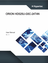
Front Panel
Item Description
System Power Button
Secondary
System Power LED
System Warning LED
Primary
System Power LED
System Warning LED
Rear Panel
Item Description
1 1300W 1+1 redundant power supply 80+ Platinum
2 2 x 10GbE SFP+ port
3 2 x GbE RJ45 port
4 1x DB-15 VGA port
5 2 x USB 3.0 port
6 1 x GbE RJ45 dedicated to BMC management port
24 x 2.5" hotswap drive bays
Primary Node Secondary Node

5
Chapter 1. Product FeaturesHA201-PV User Manual
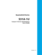
Major Components
Top view Node top view

6
Chapter 2. Hardware Setup
HA201-PV User Manual
2�1 Central Processing Unit Setup
The serverboard supports dual Xeon scalable processors and Socket P0 (LGA-3647).
2�1�1 Processor Installation
To ensure a safe and easy setup, you need to prepare before installation:
a T20 Torx screwdriver
ESD wrist strap/mat and conductive foam pad
Safe and stable environment
CAUTION
The pins of the processor socket are vulerable and easily susceptible to damage if
fingers or any foreign objects are pressed against them. Please keep the socket pro-
tective cover on when the processor is not installed.
CAUTION
When unpacking a processor, hold the processor only by its edges to avoid touching
the contacts.
Standard Processor Assembly:
A standard processor assembly is comprised of PHM(Processor Heatsink Module)
components and processor socket assembly.
Chapter 2� Hardware Setup
This information is provided for professional technicians only.
Heat sink
Standard
Processor Clip
Standard
Processor
Bolster Plate
Precsessor
Socket
PHM Components
Processor
Socket Assembly

7
Chapter 2. Hardware SetupHA201-PV User Manual
Processor Socket Assembly:
The server board includes two processor sockets (LGA-3647), supports one or two of
the Intel® Xeon® Processor Scalable Family and has a Thermal Design Power (TDP)
of up to 165W on selected models.
PHM (Processor Heatsink Module) Component:
This information is provided for professional technicians only.
Non Frabic
Processor
Non Frabic
Processor Clip
Heat sink

8
Chapter 2. Hardware Setup
HA201-PV User Manual
This information is provided for professional technicians only.
The PHM sits level with the processor socket assembly. The PHM is NOT installed
properly if it does not sit level with the processor socket assembly. Once the PHM is
seated over the processor socket assembly, the four heat sink torque screws must be
tightened in order as shown below.
Processor Heat Sink – Top View with Screw Tightening Order
CAUTION
Failure to tighten the heatsink screws in the specified order may cause damage to the
processor socket assembly. Heat sink screws should be tighted to 12 in-lbs torque
according to the indicated order on the top of the heatsink label.

9
Chapter 2. Hardware SetupHA201-PV User Manual
2�2�1 Dual Processor
This server board supports up to sixteen DDR4 2400 and 2666 Registered ECC DRAM/
Load-Reduced DIMM (LRDIMM).
NOTE
In Pavo Case, the 16 lanes from CPU#0 and the 8 lanes from CPU#1 are routed to
PCIe slot1. The lanes from the CPU#1 are routed to the PCIe slot 3 and 4.
CPU0CPU0CPU0CPU0 CPU1CPU1CPU1CPU1
DIMMCDIMMC
DIMMBDIMMB
DIMMA1DIMMA1
DIMMA2DIMMA2
DIMMJDIMMJ
DIMMHDIMMH
DIMMG1DIMMG1
DIMMG2DIMMG2
DIMM_K2DIMM_K2
DIMM_K1DIMM_K1
DIMM_LDIMM_L
DIMM_MDIMM_M
DIMM_D2DIMM_D2
DIMM_D1DIMM_D1
DIMM_EDIMM_E
DIMM_FDIMM_F
2�2 System Memory

10
Chapter 2. Hardware Setup
HA201-PV User Manual
2�2�2 Recommended Dimm Installation Order
JDIMMD2
JDIMMK2
JDIMML
JDIMMM
JDIMMK1JDIMMD1
JDIMME
JDIMMF
JDIMMC
JDIMMB
JDIMMA1
JDIMMA2
JDIMMJ
JDIMMH
JDIMMG1
JDIMMG2
DIMM Numbers DIMM ARRANGMENT
2 DIMMs
CPU0 CPU1
JDIMM_C JDIMM_J
CPU0
CPU0
CPU0
CPU0
CPU1
CPU1
CPU1
CPU1
4 DIMMs
CPU0 CPU1
JDIMM_C JDIMM_J
JDIMM_A1 JDIMM_G1
CPU0
CPU0
CPU0
CPU0
CPU1
CPU1
CPU1
CPU1
JDIMMD2
JDIMMK2
JDIMML
JDIMMM
JDIMMK1JDIMMD1
JDIMME
JDIMMF
JDIMMC
JDIMMB
JDIMMA1
JDIMMA2
JDIMMJ
JDIMMH
JDIMMG1
JDIMMG2
6 DIMMs
CPU0 CPU1
JDIMM_C JDIMM_J
JDIMM_A1 JDIMM_G1
JDIMM_F JDIMM_M
CPU0
CPU0
CPU0
CPU0
CPU1
CPU1
CPU1
CPU1
JDIMMD2
JDIMMK2
JDIMML
JDIMMM
JDIMMK1JDIMMD1
JDIMME
JDIMMF
JDIMMC
JDIMMB
JDIMMA1
JDIMMA2
JDIMMJ
JDIMMH
JDIMMG1
JDIMMG2
8 DIMMs
CPU0 CPU1
JDIMM_CJDIMM_J
JDIMM_A1 JDIMM_G1
JDIMM_D1 JDIMM_K1
JDIMM_FJDIMM_M
CPU0
CPU0
CPU0
CPU0
CPU1
CPU1
CPU1
CPU1
JDIMMD2
JDIMMK2
JDIMML
JDIMMM
JDIMMK1JDIMMD1
JDIMME
JDIMMF
JDIMMC
JDIMMB
JDIMMA1
JDIMMA2
JDIMMJ
JDIMMH
JDIMMG1
JDIMMG2

11
Chapter 2. Hardware SetupHA201-PV User Manual
JDIMM_C
JDIMM_B
JDIMM_A1
JDIMM_D1
JDIMM_F
JDIMM_J
JDIMM_H
JDIMM_G1
JDIMM_K1
JDIMM_M
JDIMM_C
JDIMM_B
JDIMM_A1
JDIMM_A2
JDIMM_D1
JDIMM_E
JDIMM_F
JDIMM_J
JDIMM_H
JDIMM_G1
JDIMM_G2
JDIMM_K1
JDIMM_L
JDIMM_M
JDIMM_C
JDIMM_B
JDIMM_A1
JDIMM_A2
JDIMM_D2
JDIMM_D1
JDIMM_E
JDIMM_F
JDIMM_J
JDIMM_H
JDIMM_G1
JDIMM_G2
JDIMM_K2
JDIMM_K1
JDIMM_L
JDIMM_M
CPU0CPU0 CPU1CPU1
JDIMMD2
JDIMMK2
JDIMML
JDIMMM
JDIMMK1JDIMMD1
JDIMME
JDIMMF
JDIMMC
JDIMMB
JDIMMA1
JDIMMA2
JDIMMJ
JDIMMH
JDIMMG1
JDIMMG2
JDIMM_C
JDIMM_B
JDIMM_A1
JDIMM_D1
JDIMM_E
JDIMM_F
JDIMM_J
JDIMM_H
JDIMM_G1
JDIMM_K1
JDIMM_L
JDIMM_M
CPU0CPU0 CPU1CPU1
JDIMMD2
JDIMMK2
JDIMML
JDIMMM
JDIMMK1JDIMMD1
JDIMME
JDIMMF
JDIMMC
JDIMMB
JDIMMA1
JDIMMA2
JDIMMJ
JDIMMH
JDIMMG1
JDIMMG2
CPU0CPU0 CPU1CPU1
JDIMMD2
JDIMMK2
JDIMML
JDIMMM
JDIMMK1JDIMMD1
JDIMME
JDIMMF
JDIMMC
JDIMMB
JDIMMA1
JDIMMA2
JDIMMJ
JDIMMH
JDIMMG1
JDIMMG2
CPU0CPU0 CPU1CPU1
JDIMMD2
JDIMMK2
JDIMML
JDIMMM
JDIMMK1JDIMMD1
JDIMME
JDIMMF
JDIMMC
JDIMMB
JDIMMA1
JDIMMA2
JDIMMJ
JDIMMH
JDIMMG1
JDIMMG2
/