I-Tech Company AMil-1900-D8e-AC 1RU 19 Inch LCD Console Drawer User manual

Category
Rack consoles
Type
User manual

The I-Tech Company i-TECH COMPANY AMil-1900-D8e-AC 1RU 19 Inch LCD Console Drawer is a military-grade KVM switch that allows you to control up to 8 computers with a single keyboard, mouse, and monitor. It supports both digital and analog video, and has a built-in 3-port USB 2.0 hub. The LCD console drawer features a sealed 104-key IP65 silicone keyboard and touchpad with backlight, and supports hotkey commands for easy switching between computers. It also has a front-mounted USB 2.0 port for convenient access to USB devices.

The I-Tech Company i-TECH COMPANY AMil-1900-D8e-AC 1RU 19 Inch LCD Console Drawer is a military-grade KVM switch that allows you to control up to 8 computers with a single keyboard, mouse, and monitor. It supports both digital and analog video, and has a built-in 3-port USB 2.0 hub. The LCD console drawer features a sealed 104-key IP65 silicone keyboard and touchpad with backlight, and supports hotkey commands for easy switching between computers. It also has a front-mounted USB 2.0 port for convenient access to USB devices.

1RU 19 LCD Console Drawer with Integrated
DVI KVM Switch - 8 Port
Military Grade
User Manual
MODEL: AMil-1900-D8e-AC
i-Tech Company LLC
EMAIL: [email protected] • WEB: www.iTechLCD.com Modified: 02-22-22
2 / 15
Contents
1. Introduction ............................................................................................................................... 3
1.1 Main Features ...................................................................................................................... 3
1.2 Package Contents ................................................................................................................ 3
1.3 LED Panel ........................................................................................................................... 4
1.3.1 Port LED Indications ................................................................................................... 4
1.3.2 7-seg port LED ............................................................................................................. 4
1.3.3 Buttons and Operations ................................................................................................ 4
1.4 Back Panels ......................................................................................................................... 5
1.5 USB2.0 Hub (at Front) ........................................................................................................ 5
2. Hardware Installation ............................................................................................................... 6
2.1 Computer/Server Installation .............................................................................................. 6
2.1.1 Connecting KVM switch to the host system ................................................................ 6
2.2 Power Up Sequence ............................................................................................................ 7
3. Usage .......................................................................................................................................... 8
3.1 Hotkey Commands .............................................................................................................. 8
3.2 DDC function ...................................................................................................................... 8
3.3 Hot Plug .............................................................................................................................. 8
3.4 Firmware Upgrade .............................................................................................................. 9
4. Specifications ............................................................................................................................ 11
5. LCD OSD Menu Setup ........................................................................................................... 12
6. Troubleshooting ....................................................................................................................... 13
7. Glossary ................................................................................................................................... 14
8. Certifications ........................................................................................................................... 15
3 / 15
1. Introduction
The 8-port DVI LCD KVM Switch including DVI-I, Single-Link, and USB 2.0 The DVI KVM
Switch allows you to control up to 8 computers with DVI display output from a single keyboard,
mouse and monitor.
It supports both digital video (1280 x 1024) and analog video (1280 x 1024) for your maximum
convenience. It also offers two USB 2.0 device hub ports for high-speed USB device sharing. We
also offer various hotkey alternatives for free configuration.
It supports HDCP compliant for digital contents protection. This KVM Switch also allows its user
to upgrade firmware contents whenever needed to enhance compatibility or functionality. This
model meets MIL-STD-810F/G standard.
1.1 Main Features
Meets MIL-STD-810F/G standard.
MIL connector for power input
One USB console controls 8 Single Link DVI computers and 2 additional USB 2.0 devices
3 port USB 2.0 hub build in; 2 locates at rear and 1 locates at front
Supported USB HUB switching independent
Supported video resolution 1280 x 1024
Support Microsoft Windows, Netware, Unix, and Linux
Support iMAC, Power MAC and Sun Micro Systems with USB port
Sealed 104-key IP65 silicone keyboard and touchpad with backlight
No Software Required easy computer selection via Push Buttons, Hotkeys
Provide various Hotkey (Scroll-Lock/ Caps-Lock/ Num-Lock/ Alt/ Ctrl/ Win) for switching
computer port and other control functions, so Hotkey function can be used in various types of
keyboards, and to avoid Hotkey duplicate problem
Keyboard status restored when switching computers
Support Mac/Sun keyboard emulation
1.2 Package Contents
1 x LCD Console Drawer with Rack Mounting Sliding Rails
1 x AC Power Cable (MIL type lock connector)
1 x CD-ROM with User Manuals, Quick Installation Guides and Utilities
4 / 15
1.3 LED Panel
Figure 1. LED Panel View
1.3.1 Port LED Indications
There are three LEDs for each port:
ONLINE LED: The Red LED on indicating a Computer is connecting to the port.
Notice: The PC99 Computer always power on the USB ports and turn on Red LED even if the
Computer is not power on.
USB HUB LED: The Green LED on indicating the USB HUB in which port.
1.3.2 7-seg port LED
The 7-segment port LED indicates the current operation PC port. It always shows 1 at this
application.
1.3.3 Buttons and Operations
There are 8 push buttons on the LED panel. The operations described in below.
(1) The “1”, “2”, “3”, “4”, “5”, “6”, “7”, “8” are the port number select buttons
You can select to the required port number by press the port number to switch the port directly.
The current operating computer port will be displayed at the 7-Segment LED.
(2) If you pressed the invalid operation, the system will stay at the previous selected port.
(3) The other buttons are not valid
LEDs for each Host Port
Port Number Select Button
7-seg LED for current operating PC port
5 / 15
1.4 Back Panels
Figure 2. Back Panel View
1.5 USB2.0 Hub (at Front)
It provides a front port USB2.0 HUB for convenient access the USB devices at front.
AC Power lock connector
USB 2.0 HUB
Connector for each Host Port
USB2.0 HUB port
6 / 15
2. Hardware Installation
Before installation, please make sure all of peripherals and computers have been turned off.
2.1 Computer/Server Installation
Figure 3. Computer/Server Installation
2.1.1 Connecting KVM switch to the host system
In order to connect the KVM switch of the host system performs the following steps:
Step 1. Power up you KVM Switch by connecting the power cord to it.
Step 2. Connect the shared USB keyboard, mouse and speaker as well as other shared USB devices to
the KVM switch.
Step 3. Connect each of your computers to the KVM switch, using the DVI video cable and USB
(Type A-to-Type B) cable).
Step 4. Power up the connected computers one by one. After your computers are powered up, the
keyboard and mouse will be recognized and now you can begin operating the KVM switch.
7 / 15
2.2 Power Up Sequence
Double check whether all cables/connectors are properly connected. You can check the keyboard
and mouse connectors to ensure the connectors and cables are connected correctly.
The recommended Power Up sequence is as follows: Monitor, KVM Switch, finally the
Computers.
Verify that all servers connected to the KVM Switch are powered on. If any connected servers have
not been powered on, it is okay to do so at this time (servers can be powered on simultaneously).
The KVM Switch emulates both a mouse and keyboard on each port and allows your server to boot
normally.
When power on the KVM switch, you will see the 7-Segment LED displayed Port 1 lights up, and
hear a beep sound. If you encounter an error, check your cable connections for that server and
reboot. If the problem persists, please refer to the chapter “Troubleshooting” in this User Manual.
3. Usage
Now that you have connected your console and servers to your KVM Switch, it is ready for use.
You can control the KVM switch by two methods:
1. Using push buttons located on the LED panel of the KVM Switch
2. Using hot-key commands through the console keyboard
It takes few seconds for the video signal to refresh after switching servers. Re-synchronization of
the mouse and keyboard signals also occurs. This is normal operation and ensures that proper
synchronization is established between the console and the connected servers.
8 / 15
3 .1 Hotkey Commands
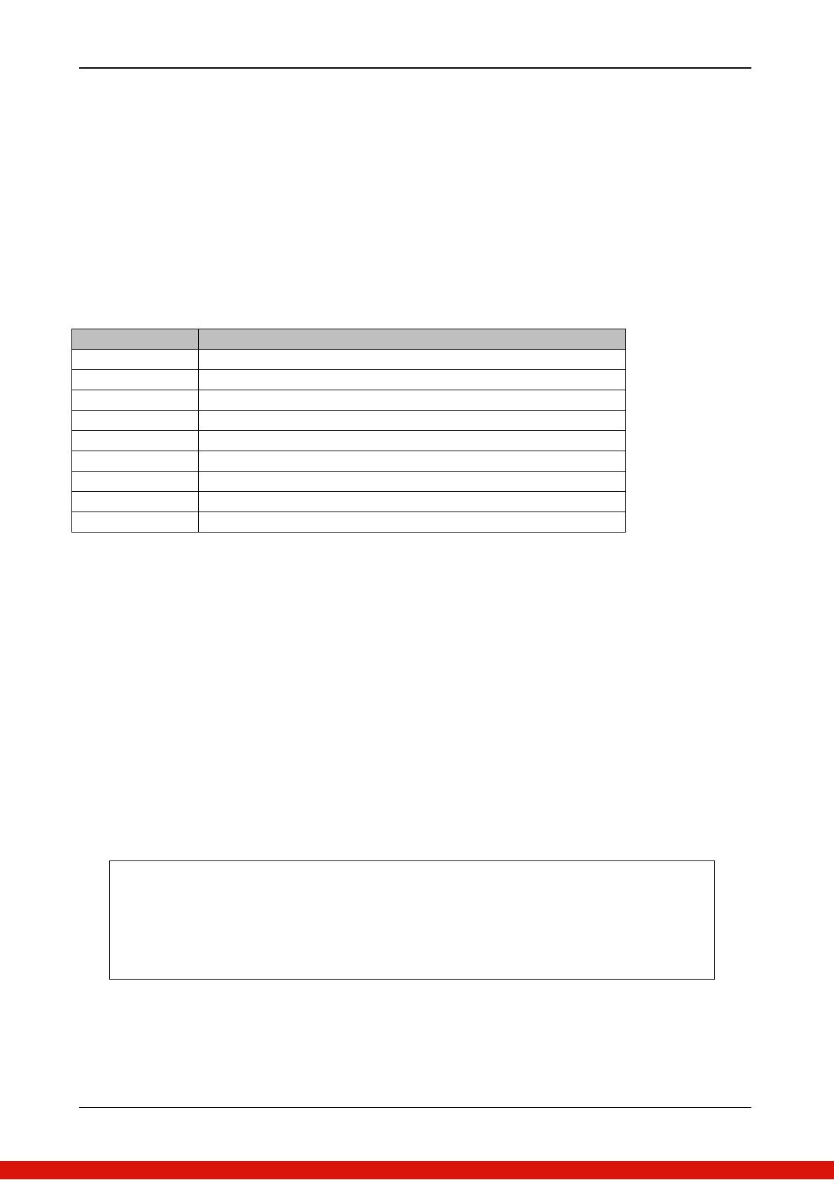
Command Function
↑ or ↓ Move selection up or down
1 ~ 8 To switch port 1 ~ port 8
F1 ~ F8 To Switch Audio of Port 1 to Port 8
B To enable/disable beep sound function.
S To activate the Auto-scan function.
H To switch USB HUB to current operating PC port.
A Switch to current operating PC port’s audio output.
G To switch audio output & USB HUB to current PC port.
F To enable Firmware upgrade function
3.2 DDC function
The KVM Switch support DDC (Display Data Channel). DDC is a VESA standard for
communication between a monitor and a video adapter. Using DDC, a monitor can inform the video
card about its properties, such as maximum resolution and color depth. The video card can then use
this information to ensure that the computer is presented with valid options for configuring the
display.
Note: The DDC function of KVM Switch will dynamically detect and copy the DDC data from the
monitor, and that data will feed to the host computer during computer startup.
3.3 Hot Plug
The KVM Switch supports “Hot Plug” function for USB keyboard and mouse connectors.
Note:
Normally, USB port is Hot pluggable, but some OS (Operation Systems), like Sun
Micro and some Unix and Linux, do not support USB Hot Plug function. If you
apply Hot Plug to this kind of OS, it will cause unpredictable behavior or shut down
the Computer. Before attempting to use Hot Plug, please make sure OS and mouse
software driver support the Hot Plug function.
You can conveniently control the LCD console drawer through simple keyboard Hotkey sequences.
To send keyboard Hotkey commands to the LCD drawer, you must press the Hotkey (default Hotkey is
Caps Lock + CapsLock) within 2 seconds. You will hear a beep sound confirming you are entering the
Hotkey mode. If you do not press any key during Hotkey mode within 2 seconds, the Hotkey mode
will be disabled and return the keyboard back to its normal state.
The default Hotkey is Caps Lock + Caps Lock, then the keys on the following table list.
9 / 15
3.4 Firmware Upgrade
Please follow the following procedures:
1. Power on the KVM unit. Use the USB Type-A to Type-B Cable connect between KVM
port1 and PC USB port. Then press Hokey + Hokey + F, appears “Beep” sound. At this time,
The KVM console will have no response.
2. The KVM now will be into upgrade mode, waiting for firmware download.
3. Unplug the KVM mouse and Keyboard, Connect the mouse to the Computer directly, Run
Firmware Upgrade Utility.exe”
Figure 4. Run Firmware Upgrade Utility
4. Click Find device to Found KVM unit, and to select the FW upgrade file. Please make sure you
select the correct FW upgrade file.
Figure 5. Find Device
Figure 6. Select Firmware Upgrade firmware File
10 / 15
5. Click upgrade, start to upgrade. The upgrade process takes about 6-10 seconds, then display Upgrade
OK and please reset your device if complete the upgrade successfully.
Figure 7. Start to Upgrade
Figure 8. Firmware Upgrade finished
6. Now the KVM unit should be running on the new firmware.
11 / 15
4. Specifications
Specification
Size: 19
Resolution: 1280 x 1024
Max Color: 16.7M
Brightness 450cd/m2
View Angle: 170/160
Contrast Ratio: 1000:1
KB/MS : USB B Type
Video : DVI-D Single Link (digital)
8
16 feet (5m)
1280 x 1024
1 x USB2.0 Type-A connector (front)
2 x USB2.0 Type-A connector (rear)
(1) Hotkey
(2) Push button
Caps-Lock
3 x LED's per Host port:
ON LINE (Red)
USB HUB (Green)
Fixed time
Through port 1 USB port
(need to use hotkey F to enter to flash mode)
Metal
-20 ~ 70 (MIL-STD-810, Method 501.5 & 502.5)
-30 ~ 80 (MIL-STD-810, Method 501.5 & 502.5)
5 ~ 95%, Non-Condensing (MIL-STD-810, Method 507.5)
Procedure VI, 50G @ 11ms (MIL-STD-810, Method 516.6)
10,000 ft Operational, 30,000 ft Storage (MIL-STD-810, Method 500.5)
19” Rack mount, 1U
447.6 x 44 x 635 (mm)
12 / 15
5. LCD OSD Menu Setup
OSD Control buttons
LCD OSD can establish and setup LCD display. Setup instructions of four buttons are as
follows:
Button
Functions
POWER
Turn on or off the LCD Display
MENU
Activate OSD menu, select a menu and press MENU key to
confirm the selection and enter the submenu.
Press this key to increase setting or scroll up the menu bar
Press this key to Decrease setting or scroll down the menu bar
Auto
Auto adjust
13 / 15
6. Troubleshooting
1. No LED display on KVM Switch
Make sure the power adapter plugged into the KVM Switch. If the LED’s still won’t light,
perform soft reset to KVM switch.
Power cycle KVM switch.
2. The computer has started up, but keyboard or mouse won’t work
Make sure your keyboard and mouse work fine if directly plugged into the computer.
Please unplug and plug in the USB connector, wait few seconds for USB bus emulations
and start up process to cmplete.
Do not press any keys on the keyboard while the selected computer is booting up.
Otherwise it might cause the keyboard error or keyboard is not detected at Host side.
Try a different keyboard, but use only 101/102/104-key keyboard.
Power cycle KVM switch.
Avoid moving the mouse or pressing the mouse buttons when switching ports.
3. No video signal is displayed on the LCD monitor.
Connect another monitor directly to the server to verify that your monitor is functioning
properly.
Please check if all connectors are connected properly
The power adapter is not connected to the KVM switch.
See next item, make sure the computer VGA output resolution match with the monitors
resolution
4. The computer resolution does not match the monitor’s resolution
Make sure the resolution works fine if directly connect the monitor to the computer.
Please turn off the computer, wait few seconds then turn on again. Notice that during
computer startup, it will try to obtain the information of the connected monitor resolution
from its related port. So before computer startup, the monitor and KVM switch should be
already ON and running.
The DDC function of KVM Switch will dynamically detect and copy the DDC data from
the monitor that attached to the LOCAL console port, and that data will feed to the host
computer during computer startup.
The recommended Power ON sequence is as follows: monitor, KVM Switch, finally the
computers.
14 / 15
7. Glossary
The following definitions are used throughout this User Manual.
Auto-Scan: A mode of operation where the KVM switch scans from one port to another, on an
ongoing basis, as configured by the user.
Console: The all-in-one term for the keyboard, video monitor, mouse, and HD
connected to a KVM switch.
Console Port: An interface receptor on the KVM switch for the console to connect to the
KVM switch via cables.
Control: When discussing switching between ports, control means that the console is capable
of sending input to the server. Control requires that the console also has focus on the port, and
is viewing it.
DDC: Short for Display Data Channel, a VESA standard for communication between a
monitor and a video adapter. Using DDC, a monitor can inform a computer’s video card about
its properties, such as maximum resolution and color depth, to ensure that the user is presented
with valid options for configuring the display.
HID: Human Interface Device, the USB device class that includes keyboards and mice.
Host/Computer Port: An interface receptor on the KVM switch for the computer/server to
connect to the KVM switch via cable.
KVM: Literally “Keyboard Video Mouse”, this term refers to technology that allows two or
more computers to be controlled by one keyboard, video monitor, and mouse; some switches
that use KVM technology enable sharing of other peripherals such as audio speakers,
microphones, and printers.
KVM Switch: A device that allows a user to access and control multiple servers from a single
console. It has at least one console port and multiple server ports.
15 / 15
8. Certifications
FCC
This equipment has been tested and found to comply with Part 15 of the FCC Rules. Operation is
subject to the following two conditions:
(1) This device may not cause harmful interference
(2) This device must accept any interference received. Include interference that may cause
undesired operation.
CE
This equipment is in compliance with the requirements of the following regulations: EN 55 022:
CLASS B.
RoHS
All contents of this package, including products, packing materials and documentation comply with
RoHS.
  • Page 1 1
  • Page 2 2
  • Page 3 3
  • Page 4 4
  • Page 5 5
  • Page 6 6
  • Page 7 7
  • Page 8 8
  • Page 9 9
  • Page 10 10
  • Page 11 11
  • Page 12 12
  • Page 13 13
  • Page 14 14
  • Page 15 15

I-Tech Company AMil-1900-D8e-AC 1RU 19 Inch LCD Console Drawer User manual

Category
Rack consoles
Type
User manual

The I-Tech Company i-TECH COMPANY AMil-1900-D8e-AC 1RU 19 Inch LCD Console Drawer is a military-grade KVM switch that allows you to control up to 8 computers with a single keyboard, mouse, and monitor. It supports both digital and analog video, and has a built-in 3-port USB 2.0 hub. The LCD console drawer features a sealed 104-key IP65 silicone keyboard and touchpad with backlight, and supports hotkey commands for easy switching between computers. It also has a front-mounted USB 2.0 port for convenient access to USB devices.

Ask a question and I''ll find the answer in the document

Finding information in a document is now easier with AI