LevelOne KVM-8908 User manual

Category
KVM switches
Type
User manual

This manual is also suitable for

KVM-8908/ KVM-8916
19” Widescreen LCD Rack Console
with 8/16-Port KVM Switch
User Manual
2 / 27
C o n t e n t s
1. Introduction ............................................................................................................................. 4
1.1 Main Features ................................................................................................................... 4
1.2 Package Contents ............................................................................................................ 5
1.3 Product Line ...................................................................................................................... 5
1.4 Front Panels ...................................................................................................................... 7
1.5 Port LED Indications ........................................................................................................ 7
1.6 7-seg BANK LED .............................................................................................................. 7
1.7 Buttons and Operations ................................................................................................... 8
1.8 Back Panels ...................................................................................................................... 8
2. Hardware Installation ............................................................................................................ 9
2.1 Desktop or Rack Mount ................................................................................................... 9
2.2 Computer/Server Installation ......................................................................................... 11
2.2.1 CAT5 KVM on Host Side ........................................................................................ 11
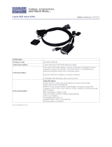
2.2.2 3-in-1 VGA Cable Installation ................................................................................ 12
2.3 Console Installation ........................................................................................................ 13
2.3.1 Local Console .......................................................................................................... 13
2.4 Optional Remote Console Installation ......................................................................... 13
2.4.1 IP Module .................................................................................................................. 13
2.4.2 CAT5 Transmitter Module ...................................................................................... 14
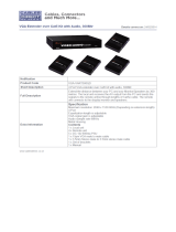
2.4.3 CAT5 KVM Receiver (R-Box) ................................................................................ 14
2.5 Power Up Sequence ...................................................................................................... 15
2.6 Daisy Chain Connection ................................................................................................ 16
3. Usage ....................................................................................................................................... 18
3.1 Hotkey Commands and OSD Operations .................................................................. 18
3.2 DDC function ................................................................................................................... 18
3.3 Hot Plug ........................................................................................................................... 18
3.4 Firmware Upgrade.......................................................................................................... 19
4. Technical Specifications .................................................................................................... 21
5. Cable Connectors ................................................................................................................ 22
5.1 3-in-1 VGA Cable............................................................................................................ 22
5.2 PS/2 keyboard to USB Changer .................................................................................. 22
5.3 Daisy Chain Cable.......................................................................................................... 22
5.4 CAT5/5E/6 Straight Through UTP/STP Cable ........................................................... 23
6. Troubleshooting ................................................................................................................... 24
7. Glossary.................................................................................................................................. 26
8. Certifications ......................................................................................................................... 27
3 / 27
F i g u r e s
Figure 1.Front Panels of the Product Line .......................................................................... 6
Figure 2.Back Panels of the Product line ............................................................................ 6
Figure 3. Front Panel View ................................................................................................. 7
Figure 4. Back Panel View .................................................................................................. 8
Figure 5. Footpads Installation ............................................................................................ 9
Figure 6. Rack Mount Installation -1 ................................................................................... 9
Figure 7. Rack Mount Installation -2 ................................................................................. 10
Figure 8. Computer/Server Installation ..............................................................................11
Figure 9. 3-in-1 VGA cable ................................................................................................ 12
Figure 10. 3-in-1 VGA Cable and PS/2 to USB Changer .................................................. 12
Figure 11. Local Console Installation ................................................................................ 13
Figure 12. IP-Module ........................................................................................................ 14
Figure 13. Daisy Chain Connection .................................................................................. 16
Figure 14. Daisy Chain through Computer Port ................................................................ 17
Figure 15. 3-in-1 VGA Cable Connectors .......................................................................... 22
Figure 16. PS/2 keyboard to USB Changer ...................................................................... 22
Figure 17. Daisy Chain Cable ........................................................................................... 22
Figure 18. CAT5/5E/6 Straight Through Cable Connector (8P8C) .................................... 23
4 / 27
1. Introduction
The Console 8/16-port KVM switch can control attaching servers and computers from local
or remote console. This KVM switch is loaded with features such as one local console port,
plus one optional CAT5-based remote console port or one optional IP-based remote
console Port, Daisy Chain, On Screen Display (OSD) Menu, Password security, Hot key
Control, Push Button and Auto Scan Control. It has complete keyboard and mouse
emulation for simultaneous computer boot-up processes.
With the CAT5-based remote console port you can remotely control servers and
computers 1000 feet away. In other words, you can locate your monitor, keyboard and
mouse up to 1000 feet away from the KVM switch. The built-in CAT5 transmitter
synthesizes VGA monitor and keyboard/mouse signals, and transmit the signals to the
remote CAT5 receiver over the popular LAN CAT5 cable.
With the IP-based remote console port you can control one or many computers locally at
the server site or remotely via the Internet using a standard browser. You can securely
gain BIOS level access to systems for maintenance, support, or failure recovery over the
Internet. Communication is secure via SSL encryption.
The console is designed as one control two viewers. Both local console and remote
console can access and view the same computer port, but only one console control at a
time. These two consoles are operating on first come first served basis, the non-controlling
console will mirror the screen from the controlling console. If the controlling console does
not have keyboard or mouse activity for 2 seconds, the other console may take over the
control right.
1.1 Main Features
Console 8/16-port KVM switch
Support one local console plus one optional remote console (CAT5 or IP)
Locate CAT5 console up to 1000 feet (300 meters) away from KVM switch with
superior auto-adjust RGB signals capability
Support Microsoft Windows, Netware, Unix, and Linux
Support iMAC, Power MAC and Sun Micro Systems with USB port
No Software Required easy computer selection via On Screen Display (OSD) Menu,
Push Buttons, Hotkeys
Provide various Hotkey (Scroll-Lock/ Caps-Lock/ Num-Lock/ Alt/ Ctrl/ Win) for
5 / 27
switching computer port and other control functions, so Hotkey function can be used in
various types of keyboards, and to avoid Hotkey duplicate problem
Support two levels of password security protections
Provide ACL (Access Control List) security function, store up to 8 independent ACLs of
controllable computer lists
Hot Plug --- add or remove connected computers without powering off the KVM switch
or computers
Plug-n-Play monitor support
Keyboard status restored when switching computers
Support Daisy Chain function with both Bus (8-layer) and Tree (2-layer) topologies
1.2 Package Contents
KVM Switch
Rack Mount Kit
1.3 Product Line
Models
KVM-8908
19” Widescreen LCD Rack Console with 8-Port KVM Switch
KVM-8916
19” Widescreen LCD Rack Console with 16-Port KVM Switch
Optional Modules
KVM-9009
KVM Remote Console Kit
Optional Cable
ACC-2101
1m PS/2 and USB KVM Cable
ACC-2102
3m PS/2 and USB KVM Cable
ACC-2103
5m PS/2 and USB KVM Cable
6 / 27
Figure 1.Front Panels of the Product Line
KR208-V11 (1+1 Console, 8 ports combo VGA KVM switch with USB local console)
KR216-V11 (1+1 Console, 16 ports combo VGA KVM switch with USB local console)
Figure 2.Back Panels of the Product line
7 / 27
1.4 Front Panels
Figure 3. Front Panel View
1.5 Port LED Indications
There are two LEDs for each port:
ONLINE LED: The Red LED on indicating a Computer is connecting to the port.
Notice: The PC99 Computer always power on the USB or PS/2 ports and turn on Red
LED even if the Computer is not power on.
SELECT LED: The Green LED on indicating the port has been selecting. The Green
LED will be flashing if there is no Computer connected to the port.
1.6 7-seg BANK LED
The 7-segment BANK LED indicates the selected bank. Maximum 8 banks can be daisy
chained.
In the daisy chain configuration, there are two methods to select the bank (KVM unit) you
want to operate: Hotkey and OSD.
LEDs for each Host Port
7-seg LED for Bank Identification
Reset Button
Bank Select
Button
Port Number
Seclect Button
8 / 27
1.7 Buttons and Operations
There are 11 push buttons on the front panel. The operations described in below.
(1) The “B” is the Bank Select Button.
You can select to the required bank number by press the “B” button.
The current accessed bank will be displayed at the 7-Segment LED.
The bank select were from 1 to 8 and go back to 1 cycling. It will increase the bank
number from the current selected bank to the next bank if you pressed the “B” button
once.
(2) The “1”, “2”, “3”, “4”, “5”, “6”, “7”, “8”, “9”, “0” are the port number select buttons
You can select to the required port number by
- Press the 2 digit port number to switch the port directly. For example if you
are in port 1 now, press “0” then “6” will switch to the port 6 immediately.
- Press the port number and wait for 2 seconds to switch the port. At this case,
you can only press single digit to select to the destination if the port number is
between port 1 to port 9.
(3) If you pressed the invalid operation, the system will stay at the previous selected port.
(4) RESET: Press the “5” and “0” button simultaneously will restart the firmware of the
KVM switch.
1.8 Back Panels
Figure 4. Back Panel View
Remote Console Port
(CAT5 T-Module)
Local Console Keyboard/Mouse Ports
Daisy Chain In
Local Console VGA Port /
Daisy Chain Out
Connector for each Host Port
9 / 27
2. Hardware Installation
Before installation, please make sure all of peripherals and computers have been turned
off.
2.1 Desktop or Rack Mount
The KVM switch unit can be placed on desktop or rack mounted.
Desktop
Stick the self-adhesive footpads that come with the package to the unit’s bottom panel at
the four corners. To install footpads, please turn upside down; and refer to the following
instructions properly for installing the footpads.
Figure 5. Footpads Installation
Rack Mounting
The KVM switch unit can be mounted on 19”/1U rack:
1. Screw the mounting brackets into the sides of the unit at the front, as shown in the
diagram below. Take note of the length of your cables so that your computers, KVM
Switch, keyboard, mouse and monitor are distanced properly.
Figure 6. Rack Mount Installation -1
10 / 27
2. Slide the unit into the rack and secure it to the rack.
Figure 7. Rack Mount Installation -2
11 / 27
2.2 Computer/Server Installation
2.2.1 CAT5 KVM on Host Side
Please refer to the “CAT5 Extender User Manual” for details. The figure below depicts the
computer/server installation.
Figure 8. Computer/Server Installation
12 / 27
2.2.2 3-in-1 VGA Cable Installation
Each computer port connector is HDDB15 type. The 3-in-1 VGA cable has a HDDB15
male connector at one end. Plug it into computer port on the rear of KVM switch. The other
end of input cable has three connectors: a HDDB15 male type for computer video, a
purple mini din 6-pin PS/2 connector for keyboard and a green mini din 6-pin PS/2
connector for mouse. Plug these three connectors into the respective ports of computer.
Repeat the same procedure for all other computers.
(a) PS/2 computer --- Plug in PS/2 mouse connector to computer mouse port, the PS/2
keyboard connector to computer keyboard port. Do not hot plug PS/2 port. If you must
do that make sure PS/2 mouse first then the PS/2 keyboard.
Figure 9. 3-in-1 VGA cable
(b) USB computer --- connect PS/2-USB changer to PS/2 keyboard connector, then plug
the changer into available USB port. This single USB port can communicate both keyboard
and mouse signals. It works as a standard HID (Human Interface Device), no extra driver
needed.
Figure 10. 3-in-1 VGA Cable and PS/2 to USB Changer
Note:
It is recommended to power off all the computers and server before the
installation. If we can not turn off the computer, for PS/2 computer, please
plug in T-dongle connectors in the following order: firstly PS/2 mouse
connector, secondly PS/2 keyboard connector, thirdly the VGA connector to
the computer.
PS/2-USB Changer
13 / 27
2.3 Console Installation
2.3.1 Local Console
Connect the monitor to the HDDB15 female port on the back of the KVM unit labeled with
the monitor symbol at the Local Console connector.
There may be USB local console or PS/2 local console. For USB local console, connect
the USB keyboard to either one of USB local port and USB mouse to the other USB port.
These USB ports are special designed for keyboard and mouse, and can not work with
USB hub or other USB devices. For PS/2 local console, connect keyboard to purple PS/2
port and mouse to green PS/2 mouse port. There is a Daisy chain port under VGA ports.
Figure 11. Local Console Installation
2.4 Optional Remote Console Installation
2.4.1 IP Module
Please refer to “IP KVM Module User Manual” for details.
IP Remote Console
Installation: Power off the KVM switch firstly. Remove the cover of the add-on slot, slide in
the IP Module and make sure the module is fully inserted into the slot.
The IP Module redirects local keyboard, mouse and video data to a remote administration
console. It allows you to control one or many computers locally at the server site or
remotely via the Internet using a standard browser.
14 / 27
Figure 12. IP-Module
2.4.2 CAT5 Transmitter Module
CAT5 Remote Console
Installation: Power off the KVM switch firstly. Remove the cover of the add-on slot, slide in
the CAT5 transmitter module and make sure the module is fully inserted into the slot.
To extending your console up to 1000 feet away by connecting the CAT5 cable to the
R-Box in the remote end.
Please refer to the “CAT5 Extender User Manual” for details.
2.4.3 CAT5 KVM Receiver (R-Box)
Please refer to the “CAT5 Extender User Manual” for details.
15 / 27
2.5 Power Up Sequence
Double check whether all cables/connectors are properly connected. You can check the
color of keyboard and mouse connectors to ensure the connectors and cables are
connected correctly.
The recommended Power Up sequence is as follows: Monitor, KVM Switch, finally
the Computers.
Verify that all servers connected to the KVM Switch are powered on. If any connected
servers have not been powered on, it is okay to do so at this time (servers can be powered
on simultaneously). The KVM Switch emulates both a mouse and keyboard on each port
and allows your server to boot normally.
When power on the KVM switch, you will see the SELECT LED of Port 1 lights up, and
hear a beep sound. If you encounter an error, check your cable connections for that server
and reboot. If the problem persists, please refer to the chapter “Troubleshooting” in this
User Manual.
16 / 27
2.6 Daisy Chain Connection
Use one end of daisy chain cable to connect to the Daisy Chain port of Master KVM
switch and connect the other end of daisy chain cable to the Local Console port of the
next Slave KVM switch. Please repeat the connection procedures for next Slave KVM
switch. You can daisy chain up to eight banks in maximum.
Note: The Daisy Chain cable is 15 lines fully connected. This is a special VGA cable,
normal VGA cable have unconnected lines.
Figure 13. Daisy Chain Connection
The console OSD menu will show only the port information of the master KVM switch.
When the master unit starts up, it will query all daisy chained Slave units, and
automatically set up the Bank ID for each Slave unit. So the 7-seg LED on the Master unit
will display 1, Slave 1 will display 2, Slave 2 will display 3, and so on. If not so, please
reset the Master unit to update the Bank ID immediately. Hot Plug function is supported in
daisy chain connection.
You can also daisy chain through computer port. This daisy chain can work with other
Bank 1 (Master)
Bank 2 (Slave1)
Bank 3 (Salve2)
17 / 27
brand of KVM switch, but you need to change the Hotkey of slave KVM switches so that
the master and slave KVM switches do not use the same Hotkey.
Figure 14. Daisy Chain through Computer Port
18 / 27
3. Usage
Now that you have connected your console and servers to your KVM Switch, it is ready for
use.
You can control the KVM switch by three methods:
1. Using push buttons located on the front panel of the KVM Switch
2. Through the OSD (On-Screen Display)
3. Using hot-key commands through the console keyboard
It takes approximately 1-2 seconds for the video signal to refresh after switching servers.
Re-synchronization of the mouse and keyboard signals also occurs. This is normal
operation and ensures that proper synchronization is established between the console and
the connected servers.
When you power on KVM switch, if the security function is enabled (default is disabled), it
will prompt a Login window waiting for user name and password. You need to pass the
authentication so can control the KVM switch.
3.1 Hotkey Commands and OSD Operations
Please refer to “Hotkey and OSD User Manual” for details.
3.2 DDC function
The KVM Switch support DDC (Display Data Channel). DDC is a VESA standard for
communication between a monitor and a video adapter. Using DDC, a monitor can inform
the video card about its properties, such as maximum resolution and color depth. The
video card can then use this information to ensure that the computer is presented with
valid options for configuring the display.
Note: The DDC function of KVM Switch will dynamically detect and copy the DDC data
from the monitor that attached to the LOCAL console port, and that data will feed to the
host computer during computer startup.
3.3 Hot Plug
The KVM Switch supports “Hot Plug” function for USB keyboard and mouse connectors.
Note:
Normally, PS/2 port is not Hot pluggable.
Normally, USB port is Hot pluggable, but some OS (Operation Systems), like
Sun Micro and some Unix and Linux, do not support USB Hot Plug function.
If you apply Hot Plug to this kind of OS, it will cause unpredictable behavior
or shut down the Computer. Before attempting to use Hot Plug, please make
sure OS and mouse software driver support the Hot Plug function.
19 / 27
3.4 Firmware Upgrade
Please follow the following procedures:
1. Power on The KVM unit. Use 3-in-1 VGA Cable and PS/2 to USB Changer, The VGA
end connect to Port1, another end connect to PC USB port. Then press Hokey +
Hokey + F, appears Beep sound. At this time, The KVM console will have no
response.
2. The KVM now will be into upgade mode, waiting for firmware download.
3. Unplug the KVM mouse and Keyboard, Connect the mouse to the Computer directly,
Run “Firmware Upgrade Utility.exe”
3.4.1. Run Firmwar Upgrade Utility
5. Click Find device to Found device, and to select the FW upgrade file. Please make
sure you select the correct FW upgrade file.
3.4.2. Find Device
3.4.3. Select Firmware Upgrade firmware File
20 / 27
6. Click upgade, start to upgrade. The upgrade process takes about 6-10 seconds, then
display Upgade OK and please reset your device if complete the upgrade
successfully.
3.4.4. Start to Upgrade
3.4.5. Firmware Upgrade finished
7. Now the KVM unit should be running on the new firmware. The FW version can be
seen on the bottom-right corner of the OSD window.
  • Page 1 1
  • Page 2 2
  • Page 3 3
  • Page 4 4
  • Page 5 5
  • Page 6 6
  • Page 7 7
  • Page 8 8
  • Page 9 9
  • Page 10 10
  • Page 11 11
  • Page 12 12
  • Page 13 13
  • Page 14 14
  • Page 15 15
  • Page 16 16
  • Page 17 17
  • Page 18 18
  • Page 19 19
  • Page 20 20
  • Page 21 21
  • Page 22 22
  • Page 23 23
  • Page 24 24
  • Page 25 25
  • Page 26 26
  • Page 27 27

LevelOne KVM-8908 User manual

Category
KVM switches
Type
User manual
This manual is also suitable for

Ask a question and I''ll find the answer in the document

Finding information in a document is now easier with AI