MAGNUM FIRST M9-ESRP Installation guide

Type
Installation guide

MAGNUM FIRST M9-ESRP is a self-powered wireless rocker pad that provides flexible control over electrical loads. With no batteries required, it generates energy from the motion of pressing the rocker and transmits unique RF messages for switching, dimming, and more. Ideal for convenient placement near entrances or exits, it offers reliable communication with other system components and enhances user convenience.

MAGNUM FIRST M9-ESRP is a self-powered wireless rocker pad that provides flexible control over electrical loads. With no batteries required, it generates energy from the motion of pressing the rocker and transmits unique RF messages for switching, dimming, and more. Ideal for convenient placement near entrances or exits, it offers reliable communication with other system components and enhances user convenience.

1
Magnum First - 1 Seneca Street, 29th Floor, M55 - Buffalo, NY 14203 - phone 716-293-1588 - www.magnumfirst.com - [email protected]
Product Installation Guide
Rocker Switch (Single,
Double) M9-ESRP / EDRP
1] Description
3] Features
6] Planning
7] Installation
Self-powered wireless Rocker Pads provide a flexible and convenient interface for switching, dimming and controlling electrical
loads. Energy generated by pressing a rocker pad is harvested and used for RF communications with Magnum devices.
Single and Double Rocker pads can be surface mounted or installed flush over an existing wall box.
• User interface for switching, dimming (when used with a dimmable controller) and more.
• Harvests energy from linear motion - no batteries.
• Transmits unique RF message each time pressed or released.
1. Decide where you want to mount the rocker pad. The standard height for wall switches is 49” or 125 cm on center.
2. Remove the wall plate from the rocker pad assembly.
3. Decide which of the two installation options is appropriate.
A. Surface Mounted Installation
i. Using a level and a pencil, lightly mark 2 small dots to align the top edge of the mounting plate.
ii. Mark the mounting screw drill points.
TIP: To remove the trim plate, use a flat-head screwdriver to depress the trim plate tabs using the 2 slots on the bottom
of the wall plate. Alternatively, use a fingernail to press down along the top groove and flex the tabs out of the slots.
5. Click the rocker pad on and o to test the mechanism.
NOTE: To activate dimming, press and hold; top button to increase, bottom button to decrease.
iv. Drill holes for the wall anchors with a 3/16” drill bit and
insert wall anchors.
v. Insert the top screw(s) loosely and level the back plate.
vi. Insert the bottom screw(s), and then hand tighten
the top screw(s).
vii. Attach the wall plate on top of the rocker pad using
the two screw holes.
NOTE: For proper assembly, make sure to align the “top” labels on the rocker pad and wall plate.
B. Flush Mounted Installation
NOTE: When installing over an existing wall box make sure any bare electrical wires are capped.
i. Remove the assembly screws which hold the wall plate, rocker pad, and mounting plate together.
ii. Use a tool to carefully pry the rocker pad free from the back plate. The back plate is not used for this option.
iii. Mount the rocker pad over the existing wall box using the two screw holes,
NOTE: For proper assembly, make sure to align the “top” labels on the rocker pad and wall plate.
iv. Attach the wall plate on top of the rocker pad using the two wall box screw holes.
4. Insert the trim plate tabs in the bottom slots, and then lightly flex the plate to insert top tabs.
Take a moment to prepare and ensure optimal communications with other system components, and for user convenience.
• Pick a convenient location, perhaps near a door where occupants enter and exit
• Consider the construction materials in the space and obstacles that may interfere with RF signals
2] Package Contents & Tools Required
• Rocker Pad • Wall Plate • Screws and Wall Anchors
• Power Drill, 3/16” bit • Screwdriver • Leveling Tool
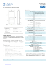
4] Dimensions
5] Technical Specifications
Part Numbers (Frequency Dependant)
ESRP = Single Rocker
EDRP = Double Rocker
M9-ESRP / EDRP (902 MHz - North America)
M8-ESRP / EDRP (868 MHz - Europe and China)
MJ-ESRP / EDRP (928 MHz - Japan)
Power Supply Mechanical energy harvesting
(power is generated by the motion of pressing the switch)
Transmission Range 80 ft. (25 m)
EEP (EnOcean Equipment Profile) F6-02-02
Dimensions Single: 4.95” H x 3.21” W x 0.74” D (126mm x 82mm x 19mm)
Double: 4.95” H x 4.52” W x 0.72” D (126mm x 115mm x 18mm)
Weight Single: 3.9 oz (112g)
Double: 5.3 oz (150g)
Environment • Indoor use only
• 14° to 104°F (-10° to 40°C)
• 20% to 95% relative humidity (non-condensing)
Agency Compliance FCC (United States) SZV-TCM3XXX, 2ANUH-LSTM300U, IC
.74”
18.84mm
.72”
18.34mm 4.52”
114.99mm
4.95”
125.76mm
4.95”
125.76mm
3.21”
81.76mm
2
Magnum First - 1 Seneca Street, 29th Floor, M55 - Buffalo, NY 14203 - phone 716-293-1588 - www.magnumfirst.com - [email protected]
Product Installation Guide
11] Compliancy
10] Warranty
U.S. Two-year Limited Warranty: Products purchased in the U.S.A. are warranted for two years from date of purchase
by Magnum Innovations to be free of defects in materials and workmanship. In the event of such defect, product
will be repaired promptly without charge or, at our option, replaced with a new product of equal or superior value
if delivered to Magnum or an Authorized Service Center, prepaid, together with the sales slip or other proof of
purchase date. This warranty excludes defects due to normal wear, abuse, shipping damage, or failure to use
product in accordance with instructions. This warranty is void in the event of unauthorized repair or modification,
or removal or defacing of the product labeling. The Magnum warranty specified herein covers material only and
does not include labor or incidental costs associated with product replacement or repair.
8] Linking
9] Troubleshooting
Two or more compatible devices can be linked and configured to provide the desired control. There are two
basic types of devices in the system; transmitters and transceivers.
Transmit-only: Transmitters are simple energy-harvesting devices that send RF messages to
communicate a condition, level, or state. Transmitters can only be linked to transceivers.
Examples > Self-powered Light Switches, Occupancy Sensors
Transmit & Receive: Transceivers are controlling devices that send as well as receive RF messages.
They also process relevant control logic, and actuate the appropriate outputs (switching a light on
or o for example). Transceivers can be linked with transmitters as well as other transceivers. A
transceiver can have up to 30 devices linked to it.
Examples > Relays, Gateways
The Rocker Pads are Transmit-only Devices.
To link the Rocker Pad to a transceiver; the transceiver must first be powered, within wireless range of the
sensor, and set to accepts links.
To Link or Unlink a Rocker Pad
1. Set the desired transceiver to the desired Link/Unlink mode. (refer to receiving device’s installation guide).
2. Click the rocker pad’s top button three times quickly. -->The rocker pad is now linked.
Refer to the “Linking” section of the transceiver/controller installation guides to verify the linking process.
This device complies with part 15 of the FCC rules and Industry Canada ICES-003. Operation is subject to the
following two conditions: (1) This device may not cause harmful interference, and (2) this device must accept any
interference received, including interference that may cause undesired operation.
IMPORTANT! Any changes or modifications not expressly approved by the party responsible for compliance could
void the user’s authority to operate this equipment.
Le présent appareil est conforme aux CNR d’Industrie Canada applicables aux appareils radio exempts de licence.
L’exploitation est autorisée aux deux conditions suivantes: (1) l’appareil ne doit pas produire de brouillage, et (2)
l’utilisateur de l’appareil doit accepter tout brouillage radioélectrique subi, meme si le brouillage est susceptible
d’en compromettre le fonc- tionnement.
IMPORTANT! Tous les changements ou modifications pas expressément approuvés par la partie responsable de
la conformité ont pu vider l’autorité de l’utilisateur pour actioner cet équipment.
PROBLEM WHAT TO CHECK
The rocker pad does not generate a message Verify the rocker pad is installed in the proper orientation
The linked device does not respond to wireless
messages
• Check for environment or range issues
• Verify the device is linked
• Check the transceiver connection and the wiring for errors
• Check if appropriate devices are linked according to
good system planning
  • Page 1 1
  • Page 2 2

MAGNUM FIRST M9-ESRP Installation guide

Type
Installation guide

MAGNUM FIRST M9-ESRP is a self-powered wireless rocker pad that provides flexible control over electrical loads. With no batteries required, it generates energy from the motion of pressing the rocker and transmits unique RF messages for switching, dimming, and more. Ideal for convenient placement near entrances or exits, it offers reliable communication with other system components and enhances user convenience.

Ask a question and I''ll find the answer in the document

Finding information in a document is now easier with AI