Page is loading ...

RL1 RL2
D.O.R.
RL1
D.O.O.
RL2
D.O.R.
RL2
OFF - ON
OFF - ON
1 1
2 2
DS1
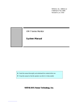
Delay & Sequencer
12345678910 11 12 13 14 15 16
POWER
NO
COM
NC
RELAY 1
NO
COM
NC
RELAY 2
WET 1 DRY 1 WET 2 DRY 2
RL1 RL2
D.O.R.
RL1
D.O.O.
RL2
D.O.R.
RL2
OFF - ON
OFF - ON
1 1
2 2
DS1
Delay & Sequencer
12345678910 11 12 13 14 15 16
POWER
NO
COM
NC
RELAY 1
NO
COM
NC
RELAY 2
WET 1 DRY 1 WET 2 DRY 2
Exterior Switch
(in circuit only
while Lock Relay
is active)
Interior Switch
(Always unlocks
and opens door)
Door Operator Input
4750 Walnut Street Suite 110
Boulder, CO 80301
www.isonas.com
Date:
10-10-2017
Drawn By:
David Tamarchenko
Version:
1.00.00
Dwg No: Sheet
1
of
1
RC-04.POE.ElectrfiedPanic.REX.DSM.ADA-
CADS1
Shown here powered by
12vdc from RC-04, verify
power consumption and
use a power supply if
necessary
Command Access Technologies
Delay Sequencer Board Part DS1
Black
Orange
Yellow
Red
White
Blue
Green
Brown
Cat5e/6 to PoE Switch
Isolate and insulate
wires not used
NC Door
Contact
Com
NC
NO
Optional
REX Input
Separate 24VDC
Power Supply
+24VDC
-24VDC
NO Dry
Contact
Input Electrfied Panic Bar
/