Page is loading ...

Installation, Operation,
and Maintenance Manual
Magnitude
®
Magnetic Bearing Centrifugal Chillers
Model WMC, C Vintage
125 to 400 Tons (440 to 1400 kW)
HFC-134a Refrigerant
50/60 Hz
IOM 1210-1
Group: Chiller
Part Number: IOM1210-1
Date: August 2014

IOM 1210-1 • MAGNITUDE
®
MODEL WMC CHILLERS 2 www.DaikinApplied.com
Table of ConTenTs
Introduction..................................3
General Description ..........................4
The Control System ..........................5
Installation...................................6
Receiving and Handling .......................6
Nameplates .................................6
Location....................................6
Clearance ..................................6
Unit Dimensions and Shipping Weight ............7
Mounting ...................................8
Water Piping ................................8
Vessel Drains at Startup .......................8
Condenser Water Temperature Control ...........9
Relief Valves ...............................10
Field Insulation .............................11
Field Power Wiring ..........................11
Communication Setup for Multiple Chillers ........18
Long Term Storage ..........................18
Pre-Start Checklist ..........................19
Operation...................................20
Operator Responsibilities .....................20
Operator Schools ...........................20
Sequence of Unit Operation ...................20
Unit Enabling/Disabling .......................20
Operator Interface Touch Screen (OITS) .........21
The Controller ..............................48
Building Automation Systems (BAS) ............58
Use with On-Site Generators ..................58
Maintenance ................................59
Service Programs ...........................59
Chiller Maintenance .........................59
Seasonal Shutdown .........................59
Seasonal Startup ...........................59
Maintenance Schedule .......................60
Appendix ...................................61
Denitions .................................61
Temperature / Pressure Chart..................64
©2014 Daikin Applied. Illustrations and data cover the Daikin Applied product at the time of publication and we reserve the right to
make changes in design and construction at any time without notice.
Manufactured in an ISO 9001 & ISO 14001 certied facility
Table of ConTenTs

www.DaikinApplied.com 3 IOM 1210-1 • MAGNITUDE
®
MODEL WMC CHILLERS
InTroduCTIon
InTroduCTIon
This manual provides installation, operation, and maintenance information for McQuay WMC Magnitude
®
centrifugal chillers with
the MicroTech
®
II controller.
WARNING
Electric shock hazard. Improper handling of this equipment can cause personal injury or equipment damage. This equipment must
be properly grounded. Connections to and service of the MicroTech
®
II control panel must be performed only by personnel that are
knowledgeable in the operation of the equipment being controlled.
CAUTION
Static sensitive components. A static discharge while handling electronic circuit boards can cause damage to the components.
Discharge any static electrical charge by touching the bare metal inside the control panel before performing any service work.
Never unplug any cables, circuit board terminal blocks, or power plugs while power is applied to the panel.
NOTICE
This equipment generates, uses, and can radiate radio frequency energy. If not installed and used in accordance with this instruction
manual, it may cause interference with radio communications. Operation of this equipment in a residential area is likely to cause
harmful interference in which case the owner will be required to correct the interference at the owner’s own expense.
Daikin Applied disclaims any liability resulting from any interference or for the correction thereof.
HAZARD IDENTIFICATION INFORMATION
DANGER
Dangers indicate a hazardous situation, which will result in death or serious injury if not avoided.
WARNING
Warnings indicate potentially hazardous situations, which can result in property damage, severe personal injury, or death if not
avoided.
CAUTION
Cautions indicate potentially hazardous situations, which can result in personal injury or equipment damage if not avoided.

IOM 1210-1 • MAGNITUDE
®
MODEL WMC CHILLERS 4 www.DaikinApplied.com
InTroduCTIon
General Description
McQuay Magnitude
®
Centrifugal Chillers are complete, self-
contained, automatically controlled, uid-chilling units featuring
oil-free, magnetic bearing compressors. All Magnitude
®
chillers
are equipped with a single evaporator and a single condenser
along with either one or two compressors depending on the
model.
Magnitude
®
chillers are designed for indoor, non-freezing
installation only. The chillers use refrigerant HFC-134a that
operates at a positive pressure over the entire operation range,
so no purge system is required.
Only normal eld connections such as water piping, relief valve
piping, electric power, and control interlocks are required,
thereby simplifying installation and increasing reliability.
Necessary equipment protection and operating controls are
included.
All McQuay International centrifugal chillers must be
commissioned by a factory-trained McQuay International
service technician. Failure to follow this startup procedure can
affect the equipment warranty.
The standard limited warranty on this equipment covers parts
that prove defective in material or workmanship. Specic
details of this warranty can be found in the warranty statement
furnished with the equipment.
NOMENCLATURE
W M C 290 D CS
Figure 1: WMC-C Major Component Locations
NOTE: Unit shown with right-hand water connections. Water connection orientation is based on facing the unit power panel.
Water-Cooled
Magnetic Bearings
Centrifugal Compressor
Vintage/Single Circuit
D = Dual Compressors
S = Single Compressor
Nominal Tons
Condenser Vessel
Evaporator Vessel
Power Panel
Compressor #2
Compressor #1
Operator
Interface Touch
Screen (OITS)
Control Panel
Tube Sheet
Tube Sheet

www.DaikinApplied.com 5 IOM 1210-1 • MAGNITUDE
®
MODEL WMC CHILLERS
InTroduCTIon
The Control System
The centrifugal MicroTech
®
II control system consists of an
operator interface touch screen (OITS), a microprocessor-
based unit controller, and compressor on-board controllers,
providing monitoring and control functions required for the
efcient operation of the chiller.
Operator Interface Touch Screen
The operator interface touch screen (OITS), see Figure 2
for an example of a screen display, is the primary device for
viewing unit operation information and entering commands
and entries into the control system. Select information from the
OITS panel can be downloaded via a USB port located in the
unit control panel.
A single OITS is used per unit. The OITS panel, see Figure
1, is mounted on a moveable arm to allow placement in a
convenient position for the operator. The OITS PC is located in
the Control Panel, as shown in Figure 3. For more information
on the OITS, see the “Operator Interface Touch Screen (OITS)”
section starting on page 21.
Figure 2: Operator Interface Touch Screen
Unit Controller
The purpose of the MicroTech
®
II unit controller is to acquire
and process data relating to chiller operation, issue instructions
to various components of the chiller, and maintain controlled
operation of the chiller. As a part of operating the chiller
successfully, the unit controller offers necessary condenser
water control. See “Condenser Water Temperature Control” on
page 9 for more information.
The controller is located in the control panel, as shown in
Figure 3. It has a 4x20 LCD display and keys for accessing
data and changing setpoints. The controller sends information
to the operator interface touch screen (OITS) for graphic
display. If the OITS should become inoperable, the controller
LCD can display most of the same information as the OITS and
can be used to operate the chiller independently of the OITS.
See “The Controller” section on page 48 for information.
Figure 3: Control Panel
Compressor On-Board Controllers
Each compressor is equipped with microprocessor controllers
and sensors that provide control and data acquisition. The data
is transmitted to other controllers and the OITS via the multi-
unit communication network. The on-board controllers control
compressor functionality and the motor/bearing system.
Figure 4: Compressor Cutaway
1. Power Electronics
2. Control Electronics
MicroTech
®
II
Controller
OITS PC
1
2

IOM 1210-1 • MAGNITUDE
®
MODEL WMC CHILLERS 6 www.DaikinApplied.com
InsTallaTIon
InsTallaTIon
Receiving and Handling
The unit should be inspected immediately after receipt for
possible damage. All McQuay International centrifugal water
chillers are shipped FOB factory and all claims for handling and
shipping damage are the responsibility of the consignee.
On units with factory-installed insulation, the insulation
is removed from the vessel lifting hole (also used for
transportation tie-downs) locations and is shipped loose. It
should be secured in place after the unit is nally placed.
Neoprene vibration isolation pads are shipped loose in the
power panel. If the unit is equipped with a shipping skid, leave
the skid in place until the unit is in its nal position. This will aid
in handling the equipment.
CAUTION
Extreme care must be used when rigging the unit to prevent
damage to the control panels and refrigerant piping. See the
certied dimension drawings included in the job submittal for
the weights and center of gravity of the unit. If the drawings
are not available, consult the local McQuay International sales
ofce for assistance.
The unit can be lifted by fastening the rigging hooks to the
four corners of the unit where the rigging eyes are located. A
spreader bar must be used between the rigging lines to prevent
damage to the control panels, piping, and electrical panels.
The spreader-bar length should be equal to, or no more than
1-foot shorter than, the distance between the lifting holes
located at opposite ends of the chiller. The unit will require a
single spreader-bar of this length capable of supporting 1.5
times the shipping weight of the unit. Separately, all cables and
hooks by themselves must also be capable of supporting 1.5
times the shipping weight of the unit.
If a knockdown option was ordered on the unit, reference the
Knockdown Installation Manual for more information.
Nameplates
There are several identication nameplates on the chiller:
• The unit nameplate is located on the Unit Control Panel.
Both the Model No. and Serial No. are unique to the unit
and will identify it. These numbers should be used to
identify the unit for service, parts, or warranty questions.
This plate also has the unit refrigerant charge and
electrical ratings.
• Vessel nameplates are located on the evaporator and
condenser. They have a National Board Number (NB)
and a serial number, either of which identify the vessel
(but not the entire unit).
Location
WMC chillers are intended only for installation in an indoor or
weather protected area consistent with the NEMA 1 rating on
the chiller, controls, and electrical panels. Equipment room
temperature for operating and standby conditions is 40°F to
104°F (4.4°C to 40°C).
Clearance
The unit must be placed in an area that allows for adequate
clearance around the unit. See Figure 5 for clearance
requirements around the sides of the chiller. Doors and
removable wall sections can be utilized to meet these
clearance requirements. There must be a minimum 3-feet
clearance above the top of the chiller. The U.S. National
Electric Code (NEC) or local codes can require more clearance
in and around electrical components and must be checked for
compliance.
Figure 5: Minimum Clearances Based on Standard Waterboxes
NOTE: Hinged type waterboxes may require more clearance. Consult a McQuay International sales representative for details.
Minimum 10’ Clearance on one end for tube service
(Models WMC125S, 145S, 145D, 200S, 225D, 250D)
Minimum 13’ Clearance on one end for tube service
(Models WMC150D, 275D, 290D, 400D)
WMC TOP VIEW
Minimum 3’ Clearance
Minimum 3’ Clearance
Minimum 4’ Clearance
in front of control boxes and electrical panels

www.DaikinApplied.com 7 IOM 1210-1 • MAGNITUDE
®
MODEL WMC CHILLERS
Unit Dimensions and Shipping Weight
Figure 6: WMC125-200S (2-pass, right-hand conguration, with grooved connections)
Figure 7: WMC145-400D (2-pass, right-hand conguration, with grooved connections)
Table 1: WMC125-400 Dimensions and Shipping Weights
* Width is based on unit without optional harmonic lters.
** Shipping weight is based on unit with standard tube conguration.
H
L W
L
H
W
Model Heat Exchanger
Length
in (mm)
Width *
in (mm)
Height
in (mm)
Shipping Weight **
lb (kg)
WMC125S E2209 / C2009 134.3 (3411) 43.5 (1105) 81.0 (2057) 5086 (2307)
WMC145S E2209 / C2009 134.3 (3411) 43.5 (1105) 81.0 (2057) 5586 (2534)
WMC145D E2209 / C2009 134.3 (3411) 43.5 (1105) 80.8 (2052) 6760 (3066)
WMC150D E2212 / C2012 169.2 (4298) 43.5 (1105) 80.8 (2052) 7709 (3497)
WMC200S E2609 / C2209 134.2 (3409) 47.2 (1199) 82.9 (2106) 6705 (3041)
WMC225D E2609 / C2209 134.2 (3409) 47.2 (1199) 83.8 (2129) 7250 (3289)
WMC250D E2609 / C2209 134.2 (3409) 47.2 (1199) 83.8 (2129) 7850 (3561)
WMC275D E2612 / C2212 169.1 (4295) 47.2 (1199) 83.9 (2131) 8221 (3729)
WMC290D E2612 / C2212 169.1 (4295) 47.2 (1199) 83.9 (2131) 9321 (4228)
WMC400D E3012 / C2612 168.5 (4280) 55.2 (1402) 94.3 (2395) 11574 (5250)
InsTallaTIon

IOM 1210-1 • MAGNITUDE
®
MODEL WMC CHILLERS 8 www.DaikinApplied.com
InsTallaTIon
Mounting
The unit must be mounted on a concrete or steel base. Make
sure that the oor or structural support is adequate to support
the full operating weight of the complete unit.
The neoprene vibration pads (shipped loose in the power
panel) should be placed under the corners of the unit (unless
the job specications state otherwise). They must be installed
so that they are ush with the edges of the unit feet.
It is not necessary to bolt the unit to the mounting slab or
framework. Should this be required by local codes, 1-1/8 inch
(28.5 mm) mounting holes are provided in the unit supports at
the four corners.
When mounted, the base pad of the unit must be level to within
± 1/2 inch across the length and width of the unit.
Water Piping
All vessels come standard with groove-type nozzles (also
suitable for welding) or optional ange connections. The
installing contractor must provide matching mechanical
connections of the size and type required. Grooved
connections are AWWA C-606. Be sure that water inlet and
outlet connections match certied drawings and nozzle
markings.
NOTE: If victaulic brand AGS
®
(Advanced Groove System)
type grooves are used on the field piping, the
contractor must supply the appropriate transition
connectors.
CAUTION
If welding is to be performed on the mechanical or ange
connections:
1. Remove the solid-state temperature sensor, thermostat
bulbs, and nozzle mounted ow switches from the wells
to prevent damage to those components.
2. Properly ground the unit or severe damage to the
MicroTech
®
II unit controller can occur.
NOTE: ASME certication will be revoked if welding is
performed on a vessel shell or tube sheet.
The water heads can be interchanged (end for end) so that
the water connections can be made at either end of the unit.
If this is done, use new head gaskets and relocate the control
sensors.
Field installed water piping to the chiller must include:
• air vents at the high points.
• a cleanable 20-mesh water strainer in water inlet lines.
• a ow proving device for both the evaporator and
condenser to prevent freeze up. Flow switches, thermal
dispersion switches, or Delta-P switches can be used.
Note that ow switches are factory installed. Additional
ow switches can be used only if they are connected in
series with the ones already provided. Connect additional
ow switches in series between CF1 and CF2, shown in
“Figure 12: Wiring Index” starting on page 12.
• sufcient shutoff valves to allow vessel isolation. The
chiller must be capable of draining the water from the
evaporator or condenser without draining the complete
system.
It is recommended that eld installed water piping to the chiller
include:
• thermometers at the inlet and outlet connections of both
vessels.
• water pressure gauge connection taps and gauges at the
inlet and outlet connections of both vessels for measuring
water pressure drop.
CAUTION
When common piping is used for both building heating and
cooling modes, care must be taken to provide that water
owing through the evaporator cannot exceed 110°F. Water
this hot can damage controls or cause the relief valve to
discharge refrigerant.
Piping must be supported to eliminate weight and strain on
the ttings and connections. Chilled water piping must be
adequately insulated.
Vessel Drains at Startup
The unit is drained of water at the factory and shipped
with open drain valves in each head of the evaporator and
condenser. Be sure to close the valves prior to lling the vessel
with uid.

www.DaikinApplied.com 9 IOM 1210-1 • MAGNITUDE
®
MODEL WMC CHILLERS
Condenser Water
Temperature Control
Condenser water control is an important consideration in chiller
plant design since condenser water temperature will directly
impact chiller operation and efciency. When the ambient
wet bulb temperature is lower than peak design, the entering
condenser water temperature from the cooling tower can
be allowed to fall, improving chiller performance. However,
operational issues may occur when the condenser water
temperatures are either too high or too low. The WMC chiller
provides several options to assist the chiller plant designer in
providing the optimum control of condenser water temperature.
Cooling Tower Control
Control of the cooling tower is required to maintain stability and
avoid operational issues. This can be achieved through a BAS
or by using the MicroTech
®
II controller. For systems utilizing a
common condenser water loop for multiple purposes, the BAS
contractor must provide the control but use of the MicroTech
®
II
output signal is still recommended.
The preferred cooling tower control utilizes a variable speed
fan. MicroTech
®
II will provide a control signal to determine the
proper fan speed. It can also control up to four stages of fan
cycling. Note that fan cycling can cause cooling tower water
temperature to uctuate as fans stage on/off, potentially adding
instability to the system.
Special consideration must be given to starting the chiller when
cold condenser water is present, such as with inverted starts or
changeover from free (tower) cooling to mechanical cooling. It
is required that some method be used to control the condenser
water to maintain proper head pressure as indicated by the
MicroTech
®
II controller.
Acceptable methods include the following (Each of these
options can be controlled by the MicroTech
®
II or through
a BAS utilizing the MicroTech
®
II output signals.):
1. Three-Way Bypass Valve Operation
A traditional method for building condenser pressure at
startup with colder condenser water is with the use of
a three-way bypass valve. The device blends warmer
water leaving the condenser with cooler water from the
cooling tower at the condenser inlet. The bypass valve
position will change until full ow from the tower to the
condenser is obtained. The MicroTech
®
II provides only
the valve position control signal. Main power to drive the
valve’s actuator must be provided by the installer. The
three-way valve should be located close to the chiller
within the equipment room to minimize the volume of
water.
2. Two-Way Valve Operation
Another condenser control method is to use a modulating
two-way control valve located on the outlet connection of
the condenser. The valve will be nearly closed at startup
to restrict water ow, which keeps generated heat in
the condenser until an acceptable minimum condenser
pressure is reached. As heat builds, the valve will open
slowly until a full ow condition from the cooling tower
is established. A separate power source is required to
provide power to the valve actuator.
3. VFD Operating with a Condenser Water Pump
A third method of condenser control for startup is
utilizing a variable frequency drive with the condenser
water pump. The speed will change as directed by the
MicroTech
®
II output signal until design ow is reached.
Speed adjustments may be required during the initial
chiller startup as determined by the service technician.
NOTE: Not using the MicroTech
®
II logic to control valves
and variable frequency drives may result in system
instability, capacity reduction, and issues starting the
chiller with cold condenser water temperature.
Condenser Pump Sequencing
It is recommended to utilize the logic built into the MicroTech
®
II
controller to start the condenser pump and maintain condenser
head pressure control. MicroTech
®
II has the capability to
operate a primary pump and a secondary standby pump. The
condenser water ow should be stopped when the chiller shuts
off. This will conserve energy and prevent refrigerant from
migrating to the condenser.
Lenient Flow Operation
For chiller startup, the condenser control systems can reduce
the ow to very low rates, which can make operation of a ow
sensing device questionable. The MicroTech
®
II controller has
a “lenient ow” feature that acts as an override of the ow
sensor while protecting the chiller by monitoring a condenser
pressure setting that is below the high pressure cutout.
Water Side Economizer Cycle Operation
Water side economizers are commonly used for ASHRAE 90.1
compliance and energy savings. This system utilizes a heat
exchanger external to the chiller when cold cooling tower water
is available to provide cooling. The most common system
has a heat exchanger used in conjunction with the chiller’s
evaporator.
The BAS contractor will need to provide controls for the heat
exchanger including isolation valves and temperature control.
The BAS contractor will also need to control the isolation
valves for the chiller. It is important to use slow-acting type
valves to prevent rapid changes in system ows. Changeover
from economizer cooling to mechanical cooling requires one
of the methods previously mentioned to maintain suitable
condenser head pressure.
Contact your local McQuay International representative for
more information on this application.
InsTallaTIon

IOM 1210-1 • MAGNITUDE
®
MODEL WMC CHILLERS 10 www.DaikinApplied.com
InsTallaTIon
Relief Valves
As a safety precaution and to meet code requirements, each
chiller is equipped with pressure relief valves located on
the condenser and evaporator for the purpose of relieving
excessive refrigerant pressure (caused by equipment
malfunction, re, etc.) to the atmosphere.
• Condensers have two 200 psi, 1.0-inch female NPT relief
valves as a set with a three-way valve separating the two
valves. (See Figure 8.) One valve remains active at all
times and the second valve acts as a standby.
• Evaporators have a single 200 psi valve. Each valve has
a 1.0-inch female NPT connection.
• When purchased with a suction isolation valve, each
suction line has a single 200 psi relief valve rated at 6.9
lb/min air with a 3/8-inch are connection.
• Vessel valve capacity is 75 lb/min air.
CAUTION
Units are shipped with refrigerant valves closed to isolate the
refrigerant in the unit condenser. Valves must remain closed
until startup by the factory service technician.
Most codes require that relief valves be vented to the outside
of a building. Relief piping connections to the relief valves must
have exible connectors.
Remove plastic shipping plugs (if installed) from the inside of
the valves prior to making pipe connections. Whenever vent
piping is installed, the lines must be in accordance with local
code requirements; where local codes do not apply, the latest
issue of ANSI/ASHRAE Standard 15 code recommendations
must be followed.
Condenser Relief Valves
As stated previously and as shown in Figure 8, condensers
have two 200 psi, 1.0-inch female NPT relief valves separated
by a three-way valve.
Figure 8: Condenser Three-Way Relief Valve
In order to ensure proper installation, it is important to know
how the three-way relief valve functions. When the stem of the
three-way valve is pushed into the valve completely, the valve
is in “Front Seated Position” and all refrigerant will ow through
the back outlet port, as shown in Figure 9. When the stem of
the three-way valve is pulled back completely, the valve is in
“Back Seated Position” and all refrigerant will ow through the
front outlet port as shown in Figure 10.
Figure 9: Three-Way Valve, Front Seated Position
Figure 10: Three-Way Valve, Back Seated Position
When the valve stem is not pushed forward or pulled back
completely, the valve is in “Mid Position,” as shown in Figure
11.
CAUTION
Do not operate the system with the three-way valve stem in
the Mid Position.
Figure 11: Three-Way Valve, Mid Position
Three-Way Valve
Relief Valves

www.DaikinApplied.com 11 IOM 1210-1 • MAGNITUDE
®
MODEL WMC CHILLERS
Field Insulation
If the optional factory-installation of thermal insulation is not
ordered, insulation should be eld installed to reduce heat
loss and prevent condensation from forming. Insulation should
cover:
• the evaporator barrel, tube sheet, and waterboxes.
• the suction line from the top of the evaporator to the
compressor inlet ange.
• the compressor support brackets welded to the
evaporator.
• the liquid line from the expansion valve to the evaporator
inlet, including the expansion valve.
• the part load balancing valve to the evaporator.
Approximate total square footage of insulation surface required
for individual packaged chillers is tabulated by evaporator code
and can be found in Table 2.
Table 2: Insulation Area Required for WMC Models
WMC Model Evaporator Code
Insulation Area
sq. ft. (m
2
)
125S E2209 78 (7.2)
145S E2209 78 (7.2)
145D E2209 78 (7.2)
150D E2212 104 (9.7)
200S E2609 92 (8.5)
225D E2609 92 (8.5)
250D E2609 92 (8.5)
275D E2612 122 (11.3)
290D E2612 122 (11.3)
400D E3012 141 (13.1)
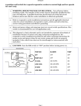
Field Power Wiring
The standard power wiring connection to Magnitude
®
chillers
is single point to a common disconnect switch, which is then
factory-wired to individual disconnect switches for each circuit.
Refer to the unit nameplate and the Daikin Tools selection
report for the correct electrical ratings.
DANGER
Qualied and licensed electricians must perform wiring. An
electrical shock hazard exists that can cause severe injury or
death.
The eld power wiring required varies depending on unit
model. See “Figure 12: Wiring Index” on page 12, “Figure
13: Controller Box Wiring” on page 14, and “Figure 14:
Power Box Single and Multi Point Wiring” on page 16 for
wiring information. These wiring diagrams are also provided
with the chiller.
Factory-mounted and wired line reactors are standard, but
not included when the optional combo harmonic lters are
included.
NOTE: Wiring, fuse, and wire size must be in accordance
with the National Electric Code (NEC). The voltage to
these units must be within ±10% of nameplate voltage
(415V units must have voltage within -13% and +6%
of nameplate voltage) and the voltage unbalance
between phases must not exceed 2%. Since a 2%
voltage unbalance will cause a current unbalance of
6 to 10 times the voltage unbalance per the NEMA
MG-1 1998 Standard, it is most important that the
unbalance between phases be kept at a minimum.
CAUTION
Do not use power factor correction capacitors with WMC
chillers. Doing so can cause harmful electrical resonance in
the system. Correction capacitors are not necessary since
VFDs inherently maintain high power factors.
Chiller Control Power
For proper operation on standby power, the chiller control
power must remain as factory-wired from a unit-mounted
transformer. Do not supply chiller control power from an
external power source because the chiller may not sense
a loss of power and may fail to perform a normal shutdown
sequence.
InsTallaTIon

IOM 1210-1 • MAGNITUDE
®
MODEL WMC CHILLERS 12 www.DaikinApplied.com
InsTallaTIon
Figure 12: Wiring Index

www.DaikinApplied.com 13 IOM 1210-1 • MAGNITUDE
®
MODEL WMC CHILLERS
InsTallaTIon

IOM 1210-1 • MAGNITUDE
®
MODEL WMC CHILLERS 14 www.DaikinApplied.com
InsTallaTIon
Figure 13: Controller Box Wiring
NOTES:
UNIT CONTROL BOX FACTORY ASSEMBLY:
JUMPERS
WJ1
AND
WJ2
MUST ONLY BE CONNECTED TO TERMINAL BLOCK
33
.
CHILLER FACTORY ASSEMBLY:
IF OPTIONAL
GFP1
IS USED THEN REMOVE JUMPER
WJ1
. OTHERWISE COMPLETE CONNECTION
WJ1
TO TERMINAL BOLOCK
38
.
IF OPTIONAL
GFP2
IS USED THEN REMOVE JUMPER
WJ2
. OTHERWISE COMPLETE CONNECTION
WJ2
TO TERMINAL BOLOCK
39
.

www.DaikinApplied.com 15 IOM 1210-1 • MAGNITUDE
®
MODEL WMC CHILLERS
NOTES:
UNIT CONTROL BOX FACTORY ASSEMBLY:
JUMPERS
WJ1
AND
WJ2
MUST ONLY BE CONNECTED TO TERMINAL BLOCK
33
.
CHILLER FACTORY ASSEMBLY:
IF OPTIONAL
GFP1
IS USED THEN REMOVE JUMPER
WJ1
. OTHERWISE COMPLETE CONNECTION
WJ1
TO TERMINAL BOLOCK
38
.
IF OPTIONAL
GFP2
IS USED THEN REMOVE JUMPER
WJ2
. OTHERWISE COMPLETE CONNECTION
WJ2
TO TERMINAL BOLOCK
39
.
InsTallaTIon

IOM 1210-1 • MAGNITUDE
®
MODEL WMC CHILLERS 16 www.DaikinApplied.com
InsTallaTIon
Figure 14: Power Box Single and Multi Point Wiring

www.DaikinApplied.com 17 IOM 1210-1 • MAGNITUDE
®
MODEL WMC CHILLERS
InsTallaTIon

InsTallaTIon
IOM 1210-1 • MAGNITUDE
®
MODEL WMC CHILLERS 18 www.DaikinApplied.com
Communication Setup for
Multiple Chillers
On multi-chiller Model WMC applications, up to four Model
WMC chillers can be LAN interconnected by eld RS485
interconnecting wiring (refer to Lines 165-174 on “Figure 12:
Wiring Index”) with the addition of an accessory communication
isolation board between each chiller connected. (The total
number of isolation boards needed is one less than the number
of chillers connected.) The isolation board can be purchased
with the unit or separately, during or after chiller installation.
N-1 boards are required.
In order for interconnection to function properly, some of the
chiller control settings will need to be modied. Interconnection
between chillers should be made at startup by the
McQuay International technician.
NOTE: Chillers connected via pLAN MUST share the same
software revision. WMC B and C vintage chillers are
compatible for interconnection via pLAN. If trying to
connect WMC A vintage chillers to eachother or to B
or C vintage chillers, consult a McQuay International
service representative. WMC chillers cannot be
pLAN interconnected with WSC, WDC, WCC or WME
centrifugal chillers.
Long Term Storage
This information applies to new units being stored waiting
for startup or to existing units that may be inoperative for an
extended period of time.
The chiller must be stored in a dry location indoors and
protected from any damage or sources of corrosion. A
McQuay International service representative must perform
an inspection and leak test of the unit on minimum quarterly
schedule, to be paid by the owner or contractor. Daikin
Applied will not be responsible for any refrigerant loss during
the storage time or for repairs to the unit during the period of
storage, or while moving the unit from the original location to
a storage facility and back to any new installation location. If
there is concern about the possibilities of damage and loss
of charge during storage, the customer can have the charge
removed and stored in recovery cylinders.
CAUTION
If the temperature of where the chiller is located is expected to
exceed 104°C (40°C), then the refrigerant must be removed.
For additional tasks required, contact McQuay International
service.

www.DaikinApplied.com 19 IOM 1210-1 • MAGNITUDE
®
MODEL WMC CHILLERS
InsTallaTIon
Pre-Start Checklist
©2014 Daikin Applied Form SF-111
MAY 2014
Pre-Start Checklist – Centrifugal Chillers
Must be completed, signed and provided to Daikin Applied Service Dept. at least 2 weeks prior to requested start date.
Job Name
Installation Location
Customer Order Number
Model Number(s)
E.O./G.O. Number(s)
Chilled Water
Yes
No
N/A
Initials
Piping Complete
Water System- flushed, filled, and vented; Water treatment in place
Pumps installed and operational (rotation checked, strainers installed and cleaned)
Controls operational (3-way valves, face/bypass dampers, bypass valves, etc.)
Water system operated and tested; flow meets unit design requirements
Condenser Water
Yes
No
N/A
Initials
Cooling tower flushed, filled, and vented; Water treatment in place
Pumps installed and operational (rotation checked, strainers installed and cleaned)
Controls (3-way valves, bypass valves, etc.) operable per IM or IOM
Water system operated and flow balance to meet unit design requirements
Electrical
Yes
No
N/A
Initials
*115 volt service completed, but not connected to control panel (when applicable)
Line Power leads(a) connected to starter; *Load leads(b) run from starter to compressor and ready
for connection by Service (Do not connect load leads to starter or compressor terminals) See Notes 1, 4
All interlock wiring complete and compliant with Daikin specifications
Starter complies with Daikin specifications
*Oil cooler solenoid wired to control panel as shown on wiring diagram (See Notes)
Pump starters and interlocks wired
Cooling tower fans and controls wired
Wiring complies with National Electrical Code and local codes (See Note 4)
Condenser pump starting relay (CP1,2) installed and wired (See Note 3)
Miscellaneous
Yes
No
N/A
Initials
*Oil cooled water piping complete. (Units with water cooled oil coolers only)
Relief valve piping complete (per local codes
Thermometers, wells, gauges, control, etc., installed
Minimum system load of 80% capacity available for testing/adjusting controls
Document Attached: Technical Breakdown from DaikinTools
Document Attached: Final Order Acknowledgement
Notes: The most common problems delaying start-up and affecting unit reliability are:
1. Field installed compressor motor power supply leads too small. Questions: Contact the local Daikin Applied sales rep* State size, number and
type of conductors and conduits installed:
a. From Line Power supply to starter
b. From starter to chiller unit (remote mounted)
2.
Centrifugal chillers with water-cooled oil coolers must have a 115-volt normally-closed water solenoid valve installed in the oil cooler water supply
line. Daikin recommends ASCO Type 8210B27 solenoid valve or approved equal and 40-mesh strainer. Daikin does not supply these components.
3. A 115 volt field supplied relay (CP1,2) must be used to start and stop condenser water pump on most applications. Cold condenser water must not
flow through condenser during compressor off cycle. Provisions have been made in control center for connecting CP relay, but must not have a rating
in excess of 100 VA.
4 Refer to NEC Article 430-22 (a)
Contractor Representative
Daikin Applied Sales Representative
Signed:
Signed:
Name:
Name:
Company:
Company:
Date:
Date:
Phone/Email:
Phone/Email:
* Does Not Apply to Magnetic Bearing Chillers (WMC/WME)

operaTIon
IOM 1210-1 • MAGNITUDE
®
MODEL WMC CHILLERS 20 www.DaikinApplied.com
operaTIon
Operator Responsibilities
It is important that the operator become familiar with the
equipment and the system before attempting operation. During
the initial startup of the chiller, the McQuay International
technician will be available to answer any questions and
instruct the proper operating procedures. It is recommended
that the operator maintain an operating log for each individual
chiller unit. In addition, a separate maintenance log should be
kept of the periodic maintenance and servicing activities.
Operator Schools
Training courses for Magnitude
®
Centrifugal Maintenance and
Operation are held through the year at the Daikin Learning
Institute in Staunton, Virginia. The school duration is three and
one-half days and includes instruction on basic refrigeration,
MicroTech
®
II controllers, enhancing chiller efciency and
reliability, MicroTech
®
II troubleshooting, system components,
and other related subjects. For more information, visit us
at www.DaikinApplied.com and click on Training or call the
Training Department. Refer to the back cover of this document
for contact information.
Sequence of Unit Operation
The following is a general chiller sequence of operation for
Magnitude
®
Model WMC chillers. Certain conditions and chiller
alarms may alter this sequence, but the chiller’s objective is to
achieve the target temperature of the leaving water.
1. Chiller enabled
With the chiller enabled via its onboard interlocks
and selected external control source, it will start the
evaporator pump and check for ow and chiller load.
2. Water ow and load proven
Once evaporator ow has been conrmed and the
chiller load proven, compressor wear balancing logic will
determine which compressor to start as the Lead.
3. Lead compressor start
As the Lead compressor approaches its maximum
capacity it will assess the need for the Lag compressor.
If the Lag compressor is needed, the Lead compressor
will signal the Lag compressor to start, and may adjust its
capacity to assist the Lag compressor start.
4. Lag compressor start
Once started, the Lag compressor will quickly ramp up to
balance the chiller load between the two compressors.
5. Dual compressor loading
As building load increases, the compressors will load
up maximizing the Inlet Guide Vane (IGV) position and
impeller speed. Maximum capacity at a given operating
condition can be found either when the compressors
have reached their maximum speed limit (Mechanical
limitation) or when the compressors have reached the
chiller’s Rated Load Amperage (Electrical limitation).
6. Dual compressor unloading
As load decreases, the compressors will unload to
sustain the water temperature set point by reducing
speed until the minimum speed limit has been reached.
If further unloading is required, the IGV assemblies will
close as required to satisfy the load.
7. Staging down to one compressor running
With the chiller running two compressors on condition
and the building load reducing to the point that one
compressor can carry the load, compressor wear
balancing logic will again determine which compressor to
shutdown.
8. Chiller shutdown
The remaining compressor will adjust capacity to
manage the chiller load until the load increases to the
point where another compressor is needed, or the load
reduces below the minimum capacity of one compressor
and the leaving water temperature goes below set point
and reaches the stop delta temperature. Anytime the
chiller is disabled, it will perform an orderly unload and
shutdown both compressors.
Unit Enabling/Disabling
There are multiple switches that will enable and disable the
chiller and its compressors:
1. Unit Switch - The top switch on the switch bracket that is
mounted inside the control box.
2. Compressor 1 Switch - Located underneath the Unit
Switch on the switch bracket.
3. Compressor 2 Switch - Located underneath the
Compressor 1 Switch on the switch bracket.
4. External Switch - Located on the outer, left side of the
control box.
5. Remote Switch - Optional. Replaces a jumper between
Field Terminals 54 and 70 (see "Figure 12: Wiring Index"
on page 12).
The switches listed above work in conjunction with the “Control
Source” that is selected in the OITS via the MODES Setpoint
Screen using Setpoint button #3. (See Figure 44 and Table 10
on page 38.) The three options for “Control Source” are:
1. Switches - This is the default mode. This mode will
ignore BAS commands.
2. Local - When this mode is set, a STOP button and an
AUTO button will appear at the top of the OITS screens,
as shown in Figure 16 on page 22. This mode will
ignore all functionality of a connected Remote
Switch. It will also ignore BAS commands.
3. BAS - This mode adds BAS capability to the Switches
functionality.
Enabling and disabling the unit and its compressors using the
switches in conjunction with the selected “Control Source” are
discussed next.
/