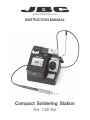
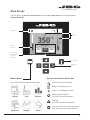
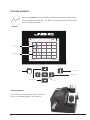
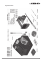
jbc CDE-BA Series is a compact soldering station that offers an intuitive user interface for quick access to station parameters. It features an intelligent heat management system that allows for precise temperature control and rapid tip recovery, increasing efficiency and tip life. The station is equipped with a quick tip changer for safe and easy cartridge replacement without the need to power down the station. Additionally, it has a USB connector for software updates and remote management capabilities, enhancing its versatility and convenience.
jbc CDE-BA Series is a compact soldering station that offers an intuitive user interface for quick access to station parameters. It features an intelligent heat management system that allows for precise temperature control and rapid tip recovery, increasing efficiency and tip life. The station is equipped with a quick tip changer for safe and easy cartridge replacement without the need to power down the station. Additionally, it has a USB connector for software updates and remote management capabilities, enhancing its versatility and convenience.


-
 1
1
-
 2
2
-
 3
3
-
 4
4
-
 5
5
-
 6
6
-
 7
7
-
 8
8
-
 9
9
-
 10
10
-
 11
11
-
 12
12
-
 13
13
-
 14
14
-
 15
15
-
 16
16
-
 17
17
-
 18
18
-
 19
19
-
 20
20


jbc CDE-BA Series User manual
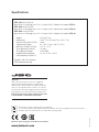
- Category
- Soldering irons
- Type
- User manual
jbc CDE-BA Series is a compact soldering station that offers an intuitive user interface for quick access to station parameters. It features an intelligent heat management system that allows for precise temperature control and rapid tip recovery, increasing efficiency and tip life. The station is equipped with a quick tip changer for safe and easy cartridge replacement without the need to power down the station. Additionally, it has a USB connector for software updates and remote management capabilities, enhancing its versatility and convenience.
Ask a question and I''ll find the answer in the document
Finding information in a document is now easier with AI
in other languages
Related papers
Other documents
-
protech TS1648 Owner's manual
-
JET JBC-1 Owner's manual
-
DENTSPLY 57H User manual
-
Alpine CDE-182R Owner's manual
-
Parkside PLLL 16 A2 Original Instructions Manual
-
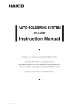 Hakko Electronics HU-200 User manual
-
Sony WX-4500X Operating instructions
-
Weller WD2M Owner's manual
-
Velleman vtss5 User manual
-
