Page is loading ...


Table of Contents
1.0 Product Overview 5............................................................................................
1.1 Package Contents ................................................................................................................ 5
1.2 System Requirements ........................................................................................................ 5
1.3 Introduction .......................................................................................................................... 6
1.4 Hardware Overview ............................................................................................................ 8
2.0 Installation 10.......................................................................................................
2.1 Hardware Installation ...................................................................................................... 10
2.1.4 Wireless Installation with WPS function...................................................... 17
2.1.3 Restore Camera back to factory settings .................................................. 16
2.4 Camera installation on PC ............................................................................................ 44
2.4.1 Camera Live installation on PC .................................................................... 44
2.4.2 Add a camera to Camera Live ...................................................................... 44
2.4.3 Play, Delete and Modify cameras ................................................................ 46
2.4.4 Muliti-viewing on one screen ........................................................................ 48
2.4.5 Video recording, Storage and Viewing ....................................................... 49
2.4.6 Snapshots, Storage and Viewing .................................................................. 50
2.2 Quick installation for iOS device ................................................................................ 25
2.2.1 Camera installation on iOS device ............................................................... 25
2.2.2 Wireless Setup on iOS device ........................................................................ 28
2.2.3 Advanced settings on iOS device ................................................................ 31
2.3 Quick installation for Android device ....................................................................... 35
2.3.1 Camera installation on Android device ..................................................... 35
2.3.2 Wireless Setup on Android device ............................................................... 38
2.3.3 Advanced settings on Android device ....................................................... 41
2.1.1 Sensor Unit Installation .................................................................................... 10
2.5 Installation via Web Browser ........................................................................................ 51
2.5.1 Viewing Camera via Web Browser .............................................................. 51
2.5.2 Wireless Setup on PC via Web Browser .................................................... 52
3.0 Advanced Configuration 57............................................................................
3.1 Network Camera Setting Interface .......................................................................... 55
3.2 Camera................................................................................................................................ 57
3.2.1 Camera Setup ...................................................................................................... 57
PHYLINK Covert Network Camera User Manual
2.1.2 Main Unit Installation........................................................................................ 13
2.1.5 Wireless Installation Considerations............................................................. 18
2.1.6 General I/O Terminal ......................................................................................... 19

3.3 Network............................................................................................................................... 62
3.3.1 Wireless Setup........................................................................................................ 62
3.3.2 TCP/IP Setup........................................................................................................... 64
3.3.3 DDNS Setup............................................................................................................ 65
3.3.4 UPNP Setup............................................................................................................ 68
3.4 Storage ................................................................................................................................ 70
3.4.1 Storage Setup ........................................................................................................ 70
3.4.2 Browse Storage .................................................................................................... 71
3.4.3 Format SD Card ................................................................................................... 71
3.4.4 Recording to NAS ............................................................................................... 72
3.2.2 Stream Setup ......................................................................................................... 58
3.2.3 OSD Setup ............................................................................................................... 61
PHYLINK Covert Network Camera User Manual
3.5 Task ................................................................................................................................ 75
3.5.1 Motion Detection ......................................................................................... 75
3.5.2 Schedule Setup .............................................................................................. 77
3.5.3 Task Management ......................................................................................... 78
3.5.3.1 Email alarm sending .......................................................................... 79
3.5.3.2 Email periodic sending ..................................................................... 81
3.5.3.3 FTP alarm sending .............................................................................. 82
3.5.3.4 FTP periodic sending ........................................................................ 84
3.6 Tools ............................................................................................................................... 92
3.6.1 System Identity ............................................................................................... 92
3.6.2 User Management ........................................................................................ 93
3.6.3 Date & Time ..................................................................................................... 94
3.6.4 Backup or Reset ............................................................................................ 95
3.6.5 Firmware Upgrade ....................................................................................... 95
3.7 Advanced functions................................................................................................. 97
3.7.1 Wizard................................................................................................................. 97
3.7.2 System................................................................................................................ 98
3.5.3.5 HTTP alarm sending .......................................................................... 85
3.5.3.6 HTTP periodic sending ..................................................................... 86
3.5.3.7 Snapshot to storage on alarm ........................................................ 87
3.5.3.8 Snapshot to storage periodically .................................................. 88
3.5.3.9 Record to storage on alarm ............................................................. 89
3.5.3.10 Record to storage continuously .................................................... 90
3.5.3.11 Send files in storage to FTP server................................................ 91
.

PHYLINK Covert Network Camera User Manual
5.0 Technical Specifications ................................................................. 102
6.0 Glossary of Terms ........................................................................... 103
4.0 Troubleshooting .............................................................................. 100
7.0 Technical Support .......................................................................... 105

1.1 Package Contents
Verify the package contents against the list below.
1.2 System Requirements
Minimum Mac System Requirements
Operating system-Mac OSX 10.4 (Tiger)
Processor-800MHz-Power PC G4 or Intel
Memory-128Mb RAM (256Mb recommended)
Minimum PC System Requirements
Operating system-Windows 2000/XP/Vista
/Windows 7/Mac/Linux
Processor-Intel Pentium III, 1GHz
Memory-256Mb RAM
Viewing System Requirements
Web Browser Setup/Viewing- IE Version 5.5 or later, Firefox,
Google Chrome, Safari & most other browsers
Real Player QuickTime and most other VLC players.
PHYLINK Covert Network Camera User Manual
PLC-128PW / PLC-128W / PLC-128P Main Unit
Camera Unit ( include 8 meter RJ11 cable)
Mounting Accessories
External Antenna (PLC-128P has no this item)
Manual and Software on CD-ROM
CAT5 Ethernet Cable
4 pin I/O connector terminal block
Power Adapter
Quick Install Guide

1.3 Introduction
Excellent HDTV 720P video quality at full frame rate, Megapixel pinhole lens.
Works over Wi-Fi, Ethernet or Power over Ethernet (PoE) 802.3af.
WPS support for easy wireless setup.
Professional Covert Network Security Camera
PHYLINK PLC-128 is a small-sized, high-performance device perfect for covertseries
installations or where a discreet and compact surveillance solution is required.
Almost impossible to discover, which keeps it protected from vandalism.
Various and Flexible Mounting
PLC-128 includes various mounting accessories for quick and easy installation.series
The Sensor unit can be mounted flat or angled on any surface, using the angled
fastening bracket. The camera can also be mounted covertly behind a thin wall,
cupboard, door and etc. with miniature size design it enables easy integration into
any hidden place.
The sensor unit and main unit are connected by an 8 meter cable, providing
flexibility to place the sensor unit in one place and the main unit elsewhere.
Excellent Quality at Full Frame Rate
PHYLINK Covert Network Camera User Manual
General I/O which is used to connect external alarm devices like PIR sensor,
Gas Detector and etc.
Audio line in for security sound monitor pickup device.
Multi-zone Motion Detection and adjustable sensitivity, alerts by Email or Push
Notifications (for iOS and Android).
Built-in Micro SD card Slot up to 128GB (SD Card not included) with remote playback
from anywhere. Free iPhone, Android Apps for Quick & Easy remote Viewing.
Smart and Connectivity

Approval Information
All our products meet the requirements of approval FCC or CE, and are granted the
FCC or CE certification. They are authorized to bear FCC or CE mark.
This device complies with Part 15 of the FCC Rules. Operation is subject to the following
two conditions:
(1) This device may not cause harmful interference, and
(2) this device must accept any interference received, including interference that may
cause undesired operation Changes and modification not expressly approved by the
manufacturer or registrant of this equipment can void your authority to operate this
equipment under Federal Communications Commissions rules.
FCC
This product complies with standards including Low Voltage Device Directive
73/23/EEC; EMC Directive 89/336/EEC and R&TTE Directive 1999/5/EC. It passed the
subject tests by the authority concerned and is authorized to bear CE mark.
CE
This equipment has been tested and found to comply with the limits for a Class B
digital device, pursuant to Part 15 of the FCC rules. These limits are designed to
provide reasonable protection against harmful interference in a residential
installation. This equipment generates, uses and can radiate radio frequency energy
and, if not installed and used in accordance with the instructions, may cause harmful
interference to radio communications.
However, there is no guarantee that interference will not occur in a particular
installation. If this equipment does cause harmful interference to radio or television
reception, which can be determined by turning the equipment off and on, the user is
encouraged to try to correct the interference by one or more of the following
measures: -Reorient or relocate the receiving antenna. -Increase the separation
between the equipment and the receiver. -Connect the equipment into an outlet on
a circuit different from that to which the receiver is connected. -Consult the dealer or
an experienced radio/TV technician for help.
PHYLINK Covert Network Camera User Manual

1.4 Hardware Overview
PHYLINK Covert Network Camera User Manual
13
2
CAM
Line In/MIC
DC12V
LAN Reset
I/O
1. Main Unit
7
5
46
9
8
11
10
8. Ethernet RJ45 connector
9. General I/O Terminal
10. Power Connector
11. Reset/WPS Button 12. Sensor Unit
12
13
14
15
16
17
2. Status indicator LED
3. External Antenna
4. RJ12 Connector for
Sensor Unit
5. Audio Line In/MIC
6. Micro SD Card slot
7. SMA connector
13. RJ11 Cable
14. RJ12 Plug
15. Cover
16. Straight mounting bracket
17. Angled mounting bracket

PHYLINK Covert Network Camera User Manual
PLC-128 series include various mounting brackets for quick and easy installation.
The sensor unit can be mounted flat or angled on any surface, using the angled
mounting bracket. The camera can also be mounted covertly behind a thin wall,
cupboard, door and etc. With miniature size design it enables easy integration into
any hidden place.
Mounting Accessories
Local storage for storing recorded image and video.
Micro SD Card slot
Connects to the included DC 12V power adapter.
Power Connector
Reset/WPS Button
Press this button for 5 seconds to reset the camera. All settings will be restored to
factory default.
Status indicator LED
Short press this button to setup a wireless connection automatically (WPS function).
After is powered on, the indicator LED shows yellow light and quickly offMain Unit
which means the system is being started. When the indicator LED shows yellow
again, it means the system has started successfully.
The indicator LED flashes during data transfer and shows red light for WPS connection
status.
General I/O Terminal
Used to connect the external wired alarm devices like PIR sensor, gas detector, siren, etc.
Note: PLC-128P has no WPS function.
The sensor unit and main unit are connected by an 8 meter cable, providing flexibility
to place the sensor unit in one place and the main unit elsewhere.
Sensor Unit and RJ11 Cable
IMPORTANT!
The sensor unit is not approved for outdoor use. The product may only be installed
in indoor environments.

2.1 Hardware Installation
PHYLINK Covert Network Camera User Manual
Flat on any surface
PLC-128 series is a small-sized, high-performance network camera perfect for covert
installations or where a discreet and compact surveillance solution is required.
Almost impossible to discover, which keeps it protected from vandalism.
2.1.1 Sensor Unit Installation
The PLC-128 series can be mounted in three different ways:
Angled on any surface, using the angled fastening bracket
Covertly behind a thin material, for example a thin wall, cupboard, door and etc.
1. Put the to the wall or ceiling, using screws and plugs appropriate forSensor Unit
the wall/ceiling material.
2. Snap on the cover.
3. Proceed to install the , seeMain Unit 3.2 Main Unit Installation.
2
1
Flat Surface Installation

PHYLINK Covert Network Camera User Manual
1. Put the angled mounting bracket to the wall or ceiling, using screws and plugs
appropriate for the wall/ceiling material. Ensure that the bracket is pointing
towards the area to be monitored.
2. Assemble the plate with the screw and align it so the arrows are vertical or horizontal.
3. Put the to the plate with the two screws.Sensor Unit
4. Snap on the cover.
5. Proceed to install the , seeMain Unit 3.2 Main Unit Installation.
2
1
34
Angled Surface Installation

PHYLINK Covert Network Camera User Manual
1. Drill a hole with 3mm diameter in the wall or ceiling. If the material is thicker than
1mm it may be necessary to expand the hole.
2. Pull off the protection on the adhesive and attach the straight mounting bracket
to the wall.
3. Insert the into the bracket, and fix with the stop screw. Ensure that theSensor Unit
cone of the is flush with the wall.Sensor Unit
4 Proceed to install the , seeMain Unit 3.2 Main Unit Installation.
3
2
1
Covert Installation

PHYLINK Covert Network Camera User Manual
2.1.2 Main Unit Installation
The Sensor Unit and Main Unit are connected by an 8 meter cable, providing flexibility
to place the Sensor Unit in one place and the Main Unit elsewhere.
Insert the RJ11 Plug into the RJ11 Jack on Main Unit.
If required, the cable can be shortened. The sensor unit is delivered with a
8 meter (26 ft) RJ11 cable.
To shorten the cable follow these steps:
2. Strip the plastic outer coating from the end of the cable.
1. Cut the cable to the desired length. Measure from the sensor unit.
12
IMPORTANT!
The RJ11 Plug must be insert into RJ11 Jack before the Main Unit is powered on.
Shorten Sensor Unit Cable
Connect the sensor unit to the main unit

PHYLINK Covert Network Camera User Manual
3. Flatten the colored wires in the order described below.
5. Use a crimping tool to fasten the connector to the cable.
4. Insert the wires all the way into a 6P6C RJ12 Plug.
Make sure that the wires stay in the correct order.
4
RJ -12 Plug
Position NO.
RJ -11 Cable
Colored wires
1
2
3
4
5
6
5
Position 6
Position 1
Null
Null
White/orange
orange
Green
White/Green
White/brown
brown
Green White/Green

PHYLINK Covert Network Camera User Manual
Connect the Main Unit to your router or switch using the network cable.
Using the included power adaptor, plug one end into the Power Connector and plug
the other end into a power outlet.
DC12V
LAN Reset
I/O
Main Unit Panel
DC Power Cable
Network Cable
Router
Note: The DHCP sever and UPnP must be enabled on your router (which is default
setting on most router) to assign a local IP address to the network camera.
If needed, please refer to your router's user manual on how to enable DHCP server
and UPnP.
The PLC-128PW can be either connected with Power Adaptor and network cable, or
optionally with a CAT-5 network cable that is connected to an 802.3af compatible
PoE Switch or PoE Injector. Under this condition, the network cable will transmit both
power and data over a single cable and you don’t need to connect the power adapter.
IMPORTANT!
Please note that for initial setup, you need to connect the camera directly to your
router or switch with a network cable. You can NOT connect wirelessly to the
camera without first setting it up via a network cable. After initial setup only the
power cable is required for the Wi-Fi connection.
Connection Using a PoE Switch or PoE Injector
Connect Network and Power

PHYLINK Covert Network Camera User Manual
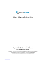
If you ever forget your admin password or have any other reason to reset the camera
to its factory settings, please use the following procedure:
2.1.3 Restore Camera back to factory settings
Make sure the camera is powered up.
Hold the down for at least 5 seconds, you’ll see theReset/WPS Button
Status indicator LED go off for a few seconds. This indicates reset is in progress.
A few seconds later the camera will restart and is now at factory settings. After reset the
user name and password will both be “admin” again.
Reset/WPS button
It is easier to use the software reset function. Login the web server of camera and
browse to > > .Setting Tools Backup or Reset
If hardware reset is needed, find the on the .Reset/WPS Button Main Unit
DC12V
LAN Reset
I/O
If using a Wi-Fi connection, the provided external antenna must be mounted to the
SMA connector on the . Please keep the antenna vertical for better signalMain Unit
strength.
The Micro SD Card must be insert to the slot before the Main Unit is powered on.
Note: The camera only supports FAT32, if the SD card is NTFS or Non FAT32 format,
you need to format it in FAT32 on PC.
Mount the Micro SD Card
Mount the antenna

PHYLINK Covert Network Camera User Manual
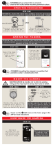
2.1.4 Wireless Installation with WPS function
You may create a Wi-Fi connect using the on the .Reset/WPS Button Camera Cable
Note: On some routers, you may need to login to the web interface and then click
on an onscreen button to activate the WPS feature. If you are not sure where the
WPS button is on your router, please refer to your router’s User Manual.
Status indicator LED
will blink red light
The camera will automatically create a wireless connection to your router.
While connecting, the will always on and your camera will reboot.Status indicator LED
Step 2
Press the on your router within 60 seconds.WPS button
WPS function also called (Quick Secure Setup) on some brands of router.QSS
Step 1
After the camera is powered on, short press the on theReset/WPS button Main Unit
and the will blink red light.Status indicator LED
Short press the
Reset/WPS button
DC12V
LAN Reset
I/O
1

2.1.5 Wireless Installation Considerations
PHYLINK Covert Network Camera User Manual
The wireless network camera lets you access your network using a wireless
connection from anywhere within the operating range of your wireless network.
However, the number, thickness and location of walls, ceilings, or other objects
that the wireless signals must pass through, may limit the range. Typical ranges
vary depending on the types of materials and background RF (radio frequency)
noise in your home or business. The key to maximizing wireless range is to follow
these basic guidelines:
1. Minimize the number of walls and ceilings between your adapter and other
network devices (such as your Network Camera) - each wall or ceiling can reduce
your adapter’s range from 3-90 feet (1-30 meters).
2. Be aware of the direct line between network devices. Position your devices
so that the signal will travel straight through a wall or ceiling (instead of at an
angle) for better reception.
3. Building Materials make a difference. A solid metal door or aluminum studs
may weaken the wireless signal. Try to position your wireless routers and wireless
network camera where the signal passes through drywall or open doorways.
4. Keep the wireless network camera at least 3-6 feet or 1-2 meters away from
electrical devices or appliances that generate RF noise.
5. If you are using 2.4GHz cordless phones or other radio frequency sources (such
as microwave ovens), your wireless connection may degrade dramatically or drop
completely. Make sure your 2.4GHz phone base is as far away from your wireless
network camera as possible. The base transmits a signal even if the phone in not
in use.
IMPORTANT!
The megapixel wireless camera requires a 4 out of 5 bar or 5 out of 5 bar signal
strength in the camera's system status page for a reliable wireless connection
with real-time video streaming. With a typical consumer grade router you should
expect the camera to work reliably 40 to 50 feet (12 to 15 meters) from the
router, with one wall in between. If the signal strength less than 3 out of 5 bar,
you may need a Wi-Fi range extender.

2.1.6 General I/O Terminal
PHYLINK Covert Network Camera User Manual
PLC-128 series provides a general I/O terminal which is used to connect external wired
alarm devices like PIR sensor, Gas Detector, etc.
The terminal definitions are described below :
Pin NO. Name
1
2
3
4
Specification
DC12V
LAN Reset
I/O
POWER
DI
DO
GND
POWER
This terminal can provide DC power to a wired alarm devices.
The max power for external device. is 12VDC ± 5%, 0.5A .
This is a optional, you can use the alarm device with a external power supply.
IMPORTANT! - The rating voltage of alarm device can not less than 12VDC,
or you will damage the alarm device.
POWER
DI
DO
GND
12VDC ± 5%, max. 0.5A (For external device)
Digital output , Max. 40VDC, max. 400mA
Digital input, OPEN/Short-to-GND
Ground

PHYLINK Covert Network Camera User Manual
DO
With a maximum load of 400mA and a maximum voltage of 40V DC, This terminal
has an open-collector NPN Darlington transistor with the emitter connected to the
GND terminal.
If used with an external relay, a diode must be connected parallel with the load,
for protecting against voltage transients.
Please refer to the following diagram for the connection method.
Be careful about choosing Open or Grounded when connecting to a alarm or
other device, you need to make the relevant settings to the camera
as the picture below:
The Grounded means that DO short to GND inside the camera.
The Open means that DO is floating inside the camera.
PWR
Apply
Digital I/O Setup
Digital input:
Active state is:
Camera
Network
Storage
Task
Tools
Live View Wizard System Support Reboot
Digital output:
Active state is:
Enable Disable
Open Grounded
Enable Disable
Open Grounded
Motion Detection
Digital I/O Setup
Schedule Setup
Task Management
Schedule: Always
Post alarm:
5
Schedule: Always
seconds (1-99)
/