Page is loading ...

HHNG5 RIDE-ON TROWEL — PUSH/PULL THROTTLE KIT INSTRUCTIONS P/N 32548 — REV. #1 (04/16/15) — PAGE 1
HHNG5
Push/Pull Throttle Kit Instructions
The following instructions are intended to assist the user in the installation of the Push/Pull Throttle Kit for use on the
HHNG5 Ride-On Trowel. Please read all assembly instructions before installing the kit.
REQUIRED TOOLS
1/4" Drive Ratchet, 6-Inch Extension, 8mm Socket
Drill, 7/16 Drill Bit
Flat Blade Screwdriver
Phillips Head Screwdriver
Needle-Nose Pliers
Hammer
11/16 End Wrench (2)
4mm Allen Wrench
PARTS
Verify that all parts are accounted for. See Figure 1 and
Table 1.
Figure 1. HHNG5 Push/Pull Throttle Kit
2
1
5
8
10
9
3
4
6
7
11
12
WORK SAFELY!
Only a qualified service technician with proper training
should perform this installation. Follow all shop safety rules
when performing this installation.
PREPARATION
1. Make sure trowel is turned off and engine is cool.
2. Place the trowel in an area free of dirt and debris. Make
sure it is on secure level ground.
Table 1. HHNG5 Push/Pull Throttle Kit (P/N 32524)
Item
No.
Part No. Description QTY. Remarks
1 32524 Kit, HHNG5 Push/Pull Throttle 1
Includes items
2-13
2 32510 Cable, Throttle 1
3 1662 Tie Wrap 2
4 30083 Slider, Throttle 1
5 32528 Spring, Ext. .38 OD X 2 L X .38 ZP 1
6 32527 Screw, HHC 10-32 X 3/4" SS 1
7 2203 Washer, Flat SAE #10 2
8 32512
Spring, Ext. .63 OD X 2.25 L X
.38 ZP
1
9 2153 Rod End 10-32 2
10 8126 P-Clamp 1/2" Loop x .25 Hole 1
11 32526 Nut, 10-32 FlexLoc 2
12 32498 Bracket, Cable 1
13 32548 Instructions, Push/Pull Throttle Kit 1

HHNG5 — PUSH/PULL THROTTLE KIT INSTRUCTIONS P/N 32548 — REV. #1 (04/16/15) — PAGE 2
DISASSEMBLY
Battery Cover Removal
1. Remove the 2 wing nuts (Figure 2) that secure the
battery hold down bar to the battery cover.
2. Set wing nuts, battery cover and hold down bar aside.
Battery Cable Disconnection
1. Disconnect the negative battery cable (BLACK) from
the battery post (Figure 2).
Figure 2. Battery Cover Removal and Cable
Disconnection
BATTERY
COVER
WING
NUT
BATTERY HOLD
DOWN BAR
NEGATIVE
(BLACK)
POSITIVE
(RED)
Front Upper Access Panel Removal
1. Unscrew the 2 thumb screws (Figure 3) located on top
of the upper access panel.
Figure 3. Access Panel Removal
2. Next, lift control access upwards and pull panel
slightly forward so that clutch cover retaining screws
(Figure 4) can be accessed.
Figure 4. Clutch Cover Retaining Screws
THUMB
SCREW
ACCESS
PANEL
CLUTCH
COVER
CLUTCH
COVER
RETAINING
SCREWS
REMOVED
ACCESS
PANEL

HHNG5 RIDE-ON TROWEL — PUSH/PULL THROTTLE KIT INSTRUCTIONS P/N 32548 — REV. #1 (04/16/15) — PAGE 3
Clutch Cover Removal
1. Remove the P-clamp (Figure 5) securing the choke
cable to the belt guard. Set the P-clamp aside in a
safe place and move the choke cable out of the way
2. Using a 7/16" wrench, remove the 1/4-20 x 3/4"
retaining screws (10) securing the belt guard panels.
Set the panels and retaining screws aside in a clean
safe place. Figure 5.
Figure 5. Clutch Cover Removal
P-CLAMP
CHOKE
CABLE
1/4-20 x 3/4”
SCREW
BELT
GUARD
COVER
Disconnecting Throttle Cable
1. Remove air filter cover for unobstructed access to the
throttle control bracket components.
2. Using a phillips head screwdriver, remove the throttle
cable wire attached to the brass hex standoff (Figure 6).
Figure 6. Throttle Cable Removal (Brass Hex
Standoff)
NOTICE
Before disconnecting any throttle components from the
control bracket, please observe (mark) the orientation
of the throttle return and governor springs.
SCREW
BRASS HEX
STANDOFF
FLAT
WASHER
HEX
SCREW
THROTTLE
CABLE
THROTTLE
RETURN
SPRING

HHNG5 — PUSH/PULL THROTTLE KIT INSTRUCTIONS P/N 32548 — REV. #1 (04/16/15) — PAGE 4
3. Next, pull the throttle cable wire from the hole opening
on the brass hex standoff.
4. Remove the brass hex standoff.
5. Once the throttle cable wire has been pulled free from
the brass hex standoff, loosen the throttle mount screw
(Figure 7) that is attached to throttle cable clamp at the
other end of control bracket.
Figure 7. Throttle Cable Removal (Cable Clamp)
6. Remove the throttle cable from the control bracket.
Throttle/Governor Springs
1. Using needle nose pliers, disconnect one end of the
governor spring as shown in Figure 8.
2. Using needle nose pliers, disconnect one end of the
throttle return spring from the slide body bracket arm
as shown in Figure 8. The throttle return spring will be
replaced with a new throttle return spring (P/N 32528).
Figure 8. Throttle/Governor Spring
Disconnection
THROTTLE
CABLE
CLAMP
THROTTLE
MOUNT
SCREW
THROTTLE
CABLE
CONTROL
BRACKET
DISCARD
SLIDE BODY
BRACKET
ARM
GOVERNOR
SPRING
THROTTLE
RETURN
SPRING
DISCONNECT
Throttle Stop Bracket/Slide Body
1. Using a 1/4" drive ratchet, 6-inch extension and a 8 mm
socket, loosen the throttle stop bracket retaining screw
(Figure 9) enough to allow the slide body bracket to be
removed. DO NOT remove retaining screw.
Figure 9. Throttle Stop Bracket
2. Using gentle pressure, remove (slide forward) the
brass slide body (P/N 30083) from the slide body
bracket as shown in Figure 10.
Figure 10. Slide Body Removal
SCREW
BRASS HEX
STANDOFF
FLAT
WASHER
HEX
SCREW
THROTTLE
CABLE
THROTTLE
RETURN
SPRING
THROTTLE
STOP BRACKET
RETAINING SCREW
THROTTLE
STOP BRACKET
ORIGINAL THROTTLE
RETURN SPRING
(REMOVE AND REPLACE)
GOVERNOR
SPRING
(REMOVE AND RETAIN)
BRASS SLIDE BODY
(REMOVE AND REPLACE)
BEND ARM FLAT
WITH PLIERS TO
REMOVE SLIDE BODY
SLIDE BODY BRACKET
(REMOVE AND REPLACE)
HIGH SPEED
ADJUSTMENT
SCREW
(REMOVE AND RETAIN)

HHNG5 RIDE-ON TROWEL — PUSH/PULL THROTTLE KIT INSTRUCTIONS P/N 32548 — REV. #1 (04/16/15) — PAGE 5
3. Remove existing governor spring from slide body
bracket and set aside. It will be used later. Discard the
existing slide body (brass) and throttle return spring (if
not already removed).
New Slide Body Installation
1. Remove the new slide body (P/N 30083 Brass) and
new throttle return spring (P/N 32528) from the kit.
2. If not attached, connect new throttle return spring
(Figure 11) through hole opening on slide body bracket.
Figure 11. New Slide Body (Brass)
3. Attach existing governor spring (Figure 12) onto slide
body bracket arm.
4. Install slide body (slide forward) onto slide body control
bracket.
5. Using a 1/4" drive ratchet, 6-inch extension and a 8 mm
socket, reposition throttle stop bracket back to its
original position. Tighten retaining screw securely.
NOTICE
Make sure to use the new slide body (P/N 30083)
provided in the kit when replacing the old slide body.
Continuing to use the old slide body may cause damage
to the trowel.
NEW THROTTLE
RETURN SPRING
ORIGINAL
GOVERNOR
SPRING
NEW BRASS
SLIDE BODY
6. Using needle nose pliers, attach the free ends of the
governor and throttle return springs to the slide body
control bracket as shown in Figure 12.
Figure 12. Throttle/Governor Spring Reconnection
Throttle Control Bracket Installation
1. Using a wrench and socket, remove and set aside the
lower left screw and washer from the engine nameplate
on the clutch and muffler side of the engine as shown
in Figure 13.
2. Place the throttle control bracket downward arm where
the screw and washer were as shown in Figure 13.
3. Reinstall the screw and washer to secure the throttle
control bracket to the engine as shown in Figure 13.
Figure 13. Throttle Control Bracket Engine
Securing
THROTTLE
RETURN SPRING
GOVERNOR
SPRING
SLIDE
BODY
BRACKET
ARM
CONNECT
SLIDE BODY
CONTROL BRACKET
THROTTLE
CONTROL BRACKET
DOWNWARD
ARM
ENGINE
NAMEPLATE
MUFFLER
SCREW AND
WASHER

HHNG5 — PUSH/PULL THROTTLE KIT INSTRUCTIONS P/N 32548 — REV. #1 (04/16/15) — PAGE 6
4. Remove the throttle mount screw securing the throttle
cable clamp. The clamp cover will not be used further.
5. Place the throttle control bracket straight arm where
the throttle mount screw was located as shown in
Figure 14.
6. Insert the throttle mount screw through the throttle
control bracket (P/N 32498) as shown in Figure 14.
Throttle mount screw was used on previous assembly
as shown in Figure 7.
Figure 14. Throttle Stop Bracket and Throttle
Mount Screw Installation
Throttle Cable Clamp/Throttle Cable Installation
1. On the new throttle cable (P/N 32510), adjust the inner
and out flat washers and nuts an adequate distance
from each other on the threaded end of the throttle
cable.
2. Insert the threaded portion of the throttle cable into
the cable slot on the throttle control support bracket
as shown in Figure 15.
3. Using two wrenches, tighten the inner and outer flat
washers and nuts against the throttle control support
bracket as shown in Figure 15.
Figure 15. Throttle Installation and Securing
THROTTLE
MOUNT
SCREW
THROTTLE
CONTROL
BRACKET
DOWNWARD ARM
(SECURED TO ENGINE
NAMEPLATE)
STRAIGHT
ARM
THROTTLE
CONTROL BRACKET
INNER FLAT
WASHER
AND NUT
OUTER
FLAT
WASHER
AND NUT
THROTTLE
CONTROL BRACKET
REAR ARM ENGINE
CONNECTION
THROTTLE
CONTROL
SUPPORT
BRACKET
Rod End/Throttle Cable Installation
1. Install the rod end completely on the cable, and tighten
the jam nut as shown in Figure 16.
2. Insert a 10-32 flat washer and 10-32 x 3/8" screw up
through the bottom of the rod end.
3. While holding the flat washer and screw, place a 10-32"
flexloc nut over the threaded end of the 10-32 x 3/8"
screw to secure the rod end to the slide body bracket.
4. Using a wrench, tighten the nut on the throttle cable to
be flush with the rod end.
Figure 16. Throttle Cable/Rod End Installation
5. Using an antiseize lubricant, lubricate both ends of
the push/pull throttle cable. Pull the wiper back and
lubricate inside boot as shown in Figure 17.
Figure 17. Throttle Cable Boot Lubrication
6. Reinstall the clutch cover. Secure clutch cover to
the frame using retaining screws (4). Tighten screws
securely.
7. Reinstall upper access panel. Secure panel to frame
with thumb screws (2). Tighten securely.
8. Reinstall air cleaner cover.
THROTTLE
CABLE
ROD END
10-32 x 3/8” SCREW
AND 10-32 FLAT
WASHER
10-32
FLEXLOC
NUT
NUT
LUBRICATE
THROTTLE CABLE BOOT

HHNG5 RIDE-ON TROWEL — PUSH/PULL THROTTLE KIT INSTRUCTIONS P/N 32548 — REV. #1 (04/16/15) — PAGE 7
Throttle Side Foot Riser Removal
1. Remove the 5/16-18 x 1" nuts (2) and 5/16-18 washers
(2) that secure the foot riser to platform. These nuts are
located on the underside of the foot platform.
2. Lay foot riser on its side.
3. Unhook throttle wire (Figure 18) from the foot pedal
linkage and throttle standoff.
4. Remove the throttle standoff (Figure 18) attached to
the foot pedal linkage. The throttle standoff will not be
used anymore.
5. Remove the spring (Figure 18) attached to the foot
pedal linkage.
Figure 18. Throttle Wire Removal
6. At the rear of the foot riser, loosen the cable adjustment
fitting ring (Figure 19) and remove the existing throttle
cable and adjuster from the trowel and discard.
Figure 19. Throttle Cable Removal
THROTTLE
WIRE
FOOT PEDAL
LINKAGE
THROTTLE
STANDOFF
SNAP
RING
SPRING
CABLE
ADJUSTMENT
FITTING
THROTTLE
CABLE
7. Route the new throttle cable around the back side of
the engine and slide the cable underneath the opening
at the bottom of lower access panel.
8. Using a 7/16" drill bit, drill out the existing lock nut hole
as shown in Figure 20. Make sure to remove all burrs
from drilled hole.
9. Next, continue to route throttle cable and throttle wire
through the cable adjustment fitting (Figure 19) located
at the rear of the foot riser. A small jam nut, large jam
nut, and washer will need to be removed.
Figure 20. 7/16" Expanded Drill Lock Nut
10. Locate and remove the second rod end (P/N 2153),
10-32 x 3/8" screw (P/N 32527), 10-32 flat washer
(P/N 2203), and 10-32 flexloc nut (P/N 32526) from
the kit.
11. Insert throttle wire through the hole opening in foot
riser. Using needle nose pliers, pull throttle wire until
there is no slack in the cable wire.
12. Using an antiseize lubricant, lubricate both ends of
the push/pull throttle cable. Pull the wiper back and
lubricate inside boot as shown in Figure 21.
Figure 21. Foot Pedal Cable Assembly
13. Install the rod end on the throttle cable completely.
Then set the jam nut.
7/16” DRILL BIT
LUBRICATE

HHNG5 — PUSH/PULL THROTTLE KIT INSTRUCTIONS P/N 32548 — REV. #1 (04/16/15) — PAGE 8
14. Install the rod end, screw, washer, and nuts where the
throttle standoff used to be on the foot pedal linkage
as shown in Figure 22.
15. Attach the new spring (P/N 32512).
Figure 22. Foot Riser Connections
16. To secure the throttle cable to the foot riser, tighten
the cable adjustment fitting nuts securely. Reference
Figure 19.
17. Place foot riser back in the upright position and secure
to foot platform using the retaining screws (2).
18. Locate and remove the P-clamp (P/N 8126) from the
kit. P-clamp the throttle cable and attach to fan guard
as shown in Figure 23.
Figure 23. Securing Throttle Cable
THROTTLE
WIRE
ROD
END
10-32 x 3/8” SCREW
AND
10-32 FLAT WASHER
10-32
FLEXLOC NUT
NUT
NEW SPRING
P-CLAMP
(P/N 8126)
THROTTLE
CABLE
FAN
GUARD
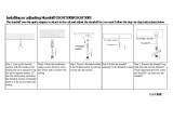
High Speed Throttle Adjustment Setting
This final step is intended to adjust and set the throttle cable
with the engine operating at full speed. This adjustment is
made at the HIGH speed adjustment screw (Figure 24).
1. With engine at full operating speed (pressing down on
throttle pedal), engine RPMs should not exceed 3800
RPM ± 20 RPM’s.
2. If engine speed exceeds 3800 RPM ± 20 RPMs, adjust
HIGH speed adjustment screw until operating speed is
set to 3800 RPM ± 20 RPMs. This can be accomplished
by using a strobe light or clip-on tachometer.
Figure 24. High Speed Adjustment Screw
HIGH SPEED
ADJUTSMENT SCREW

HHNG5
Throttle Push/Pull Kit Instructions
Your Local Dealer is:
HERE’S HOW TO GET HELP
PLEASE HAVE THE MODEL AND SERIAL
NUMBER ON-HAND WHEN CALLING
United StateS
Multiquip Corporate Office MQ Parts Department
18910 Wilmington Ave.
Carson, CA 90746
Contact: [email protected]
Tel. (800) 421-1244
Fax (310) 537-3927
800-427-1244
310-537-3700
Fax: 800-672-7877
Fax: 310-637-3284
Service Department Warranty Department
800-421-1244
310-537-3700
Fax: 310-537-4259 800-421-1244
310-537-3700
Fax: 310-943-2249
Technical Assistance
800-478-1244 Fax: 310-943-2238
Canada
United Kingdom
Multiquip Multiquip (UK) Limited Head Office
4110 Industriel Boul.
Laval, Quebec, Canada H7L 6V3
Contact: jmar[email protected]
Tel: (450) 625-2244
Tel: (877) 963-4411
Fax: (450) 625-8664
Unit 2, Northpoint Industrial Estate,
Globe Lane,
Dukinfield, Cheshire SK16 4UJ
Contact: [email protected].uk
Tel: 0161 339 2223
Fax: 0161 339 3226
© COPYRIGHT 2015, MULTIQUIP INC.
Multiquip Inc
, the MQ logo and the Whiteman logo
are registered trademarks of Multiquip Inc. and may not be used, reproduced, or altered without written permission. All other
trademarks are the property of their respective owners and used with permission.
This manual
MUST accompany the equipment at all times. This manual is considered a permanent part of the equipment and should remain with the unit if resold.
The information and specifi cations included in this publication were in effect at the time of approval for printing. Illustrations, descriptions, references and technical data contained in
this manual are for guidance only and may not be considered as binding. Multiquip Inc. reserves the right to discontinue or change specifi cations, design or the information published
in this publication at any time without notice and without incurring any obligations.
/