Page is loading ...

...... 9
.... 18
.... 12
......7
D
......1
NL
PL
GB
S
UAE
F
DK
GR
E
N
CZ
I
FIN
H
......2
......3
......4
......5
......6
......8
.... 10
.... 11
....13
....14
....15
P
....16
.... 17
TR
SK
SLO
HR
.... 19
.... 20
....22
....21
BG
EST
LV
LT
....23
....24
.... 26
.... 25
RO
CN
RUS
.... 27
Aquatower 3000
95.047.431/ÄM 209162/04.07
Aquatower 3000
27 203
.... 17
.... 35
.... 23
....13
D
......1
NL
PL
GB
S
UAE
F
DK
GR
E
N
CZ
I
FIN
H
......3
......5
......7
......9
....11
....15
.... 19
.... 21
....25
....27
....29
P
....31
.... 33
TR
SK
SLO
HR
.... 37
.... 39
....43
....41
BG
EST
LV
LT
....45
....47
.... 51
.... 49
RO
RUS
RUS
.... 27

III
1 2
3
B1
B
4
3
m
m
G
5
10mm / 24mm
3mm
RZ 2
ø 6mm

III IV

3
GB
Application
In order to ensure correct operation, a pressure of at least 1.5 bar is necessary at the
shower system.
Caution:
Operation with instantaneous heaters (electrically or gas operated) is not possible.
All thermostats are adjusted in the factory at a flow pressure of 3 bar on both sides.
Should temperature deviations occur on account of special installation conditions,
the thermostat must be adapted to local conditions (see Adjustment).
Specifications
Minimum flow pressure 1.5 bar
Max. operating pressure 10 bar
Recommended flow pressure 2 - 5 bar
Test pressure 16 bar
Flow rate at 3 bar flow pressure
Handspray approx. 13.0 l/min
Side showers approx. 30.0 l/min
Overhead spray approx. 15.0 l/min
Overhead spray and side showers approx. 37.0 l/min
Handspray and side showers approx. 35.0 l/min
Max. water temperature at hot water supply 80 °C
Recommended max. flow temperature
(energy saving) 60 °C
Safety stop 38 °C
Hot water temperature at supply connection
min. 2 °C higher than mixed water temperature
Cold water connection right
Hot water connection left
If static pressure exceeds 5 bar, a pressure reducing valve must be fitted.
Delivery specification, see fold-out page VII.
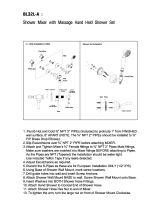
Tools required, see fold-out page I.
Installation
Make up unions, if not yet in place.
For union fastening dimensions (cold and hot water connection), see fold-out page II
Fig. [1].
(unions can be located on the left or the right-hand wall).
The hot water supply must be connected above and the cold water supply below.
The installation dimensions for the fitting relate to the standing level of the shower
stand.
The installation height of the showers from the standing
level must be observed in order to comfortably operate
the fittings, see Fig. [1].
• Install union elbows, see Fig.[2].
(the lower union elbow must be installed approx. 20° offset).
• Drill ø6mm fixing holes for fixing brackets, see Fig. [3].
Flush pipes thoroughly
The following dismantling steps must be performed before commencing
installation of the shower system:
Remove fixing screws (B1) and detach cover (B), see Fig. [4].
Installation of shower system
1. Install fixing bracket (G), see Fig. [3] and [5].
2. Hang the shower system on the upper fixing bracket (G) and secure using
washer (G1) and nut (G2), see fold-out page IV Fig. [6].
3. Pull the shower system away from the wall at the bottom and screw the pressure
hoses (F) with seals (F1) onto the union elbows.
4. Fix the shower system at the top and bottom using washers (G1) and nuts (G2).
5. Reinstall upper cover (B), see fold-out page II Fig. [4].
6. Tighten fixing rings (C) for middle cover (D) using installation aid (A), see
Fig. [7].
7. Place installation tool (A) on the lower cap (H) for safekeeping and install
cap (H) with screws (H1), see Fig. [8].
8. Attach escutcheons (J) to all side sprays, see Fig. [7].
9. Install wall holder (M1) for handspray, (see operating instructions accompanying
wall holder).
10. Attach spray hose (L) with seal (L1) to union nipple (K) and install hand
spray (M), see Fig. [9].
(see also enclosed hand spray operating instructions).
11. Insert hand spray (M) in the wall holder (M1).
12. Install overhead spray, see Fig. [10].
Shut-off knob (P) operation, see fold-out page V, Fig. [11].
Shut-off knob in central position = closed
Turn shut-off knob clockwise = aperture to handspray
Press button (P3) and
turn shut-off knob anti-clockwise = aperture to overhead spray
Adjusting
For temperature adjustment, see Figs. [11] and [12].
1. Open the shut-off knob (P) to the handspray position and measure the
temperature of the water running out using a thermometer, see Fig. [11].
2. With the safety stop depressed, turn thermostat knob (O) until the water
temperature reaches 38 °C.
3. Lever out cap (O1), see Fig. [12].
4. Hold thermostat knob (O) in this position and remove screw (O2).
5. Pull off thermostat knob (O) and reinstall in such a way that the mark
on the knob aligns with the 38 °C lettering on the cover (D).
6. Hold thermostat knob (O) and reinstall screw (O2).
7. Refit cap (O1).
Temperature limitation
The safety stop limits the temperature range to 38 °C. If a higher temperature is
required, the 38 °C limit can be overridden by depressing the safety stop.
Please pass these instructions on to the fitting user!
The right to make technical modifications is reserved!

4
Adjusting the economy stop
Volume adjustment, see Figs. [13] and [14].
• The flow rate is limited by a stop adjusted at the factory.
If a higher rate is required, the stop can be overridden by depressing the
economy button (X3), see Fig. [13].
To adjust the stop, proceed as follows:
1. Close shut-off valve.
2. Lever out cap (X1) and remove screw (X2).
3. Detach shut-off knob (X), splined adapter (X4) and economy stop (X5).
4. Reinstall economy stop (X5) in the desired position. For adjustment range,
see Fig. [14].
5. Reinstall splined adapter (X4) and shut-off knob (X) with economy button (X3)
pointing to the right. Install screw (X2) and refit cap (X1), see Fig. [13].
Volume control for side showers, see Fig. [15].
Prevention of frost damage
When the domestic water system is drained, thermostats must be drained separately,
since non-return valves are installed in the hot and cold water connections. For this
purpose, the shower system must be removed from the wall.
Maintenance
Inspect and clean all parts, replace if necessary and grease with special grease if
required.
Shut off the hot and cold water supply.
I. Side shower with non-return valve (Q5), see Fig. [16].
1. Remove screw (Q1) using a screwdriver.
2. Completely remove spray base (Q).
3. Detach housing (Q2).
4. Remove washer (Q3) by pressing in the ball (Q4).
5. Remove ball (Q4).
6. Pull out non-return valve (Q5) using pliers.
Assemble in reverse order.
When installing the washer (Q3) the ball (Q4) must be pressed slightly into the
housing.
II. Hand, overhead spray and side showers, see Fig. [17].
The function of the SpeedClean nozzles is guaranteed for a period of five years.
Simply rub SpeedClean nozzles in order to remove limescale deposit from spray jets
of hand, overhead spray and side showers.
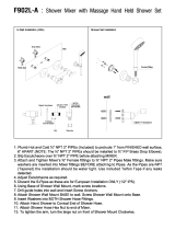
III. Thermostatic cartridge, see fold-out page VI Fig. [18].
1. Lever out cap (O1).
2. Remove screw (O2).
3. Remove temperature selection handle (O).
4. Remove clip (R1).
5. Remove stop ring (R2).
6. Remove adjusting nut (R) with overload unit (R3).
7. Remove sleeve (S1).
8. With a 22mm open-ended spanner, unscrew and remove thermostatic
cartridge (S).
Assemble in reverse order.
Readjustment is necessary after every maintenance operation on the thermostatic
cartridge (see Adjustment).
IV. Non-return valve (T), see Fig. [19].
1. Lever out cap (O1).
2. Remove screw (O2) and detach thermostat knob (O).
3. Lever out rosettes (J) and remove fixing rings (C) using installation tool (A).
4. Detach spray hose (L) and remove union nipple (K) using a 12mm hexagon socket
spanner.
5. Remove cover (D).
6. Remove non-return valve (T) with 17mm socket wrench.
Non-return valve (K2)
1. Detach spray hose (L) and remove union nipple (K) using a 12mm hexagon socket
spanner.
2. Remove non-return valve (K2).
Assemble in reverse order.
V. Aquadimmer, see Fig. [20].
1. Lever out cap (P1).
2. Remove screw (P2) and detach shut-off knob (P).
3. Remove splined adapter (U) and stop (V).
4. Remove Aquadimmer (W) using a 19mm open-ended spanner.
Assemble in reverse order.
Observe the correct installation position, see Figs. [21] and [22].
- The dissimilar pins (W1) and (W2) must engage in the corresponding bores in the
housing, see Fig. [21].
- Attach stop (V) so that the arrow (V1) aligns with the mark (D1) on the cap, see
Fig. [22].
- Turn shut-off spindle of the Aquadimmer so that face (W3) points upwards.
- Fit and turn splined adapter (U) so that arrow (U1) aligns with marking (D1) on the
shower system.
- Attach shut-off knob (P), making sure that button (P3) points to the right.
VI. Ceramic headpart, see Fig. [23].
1. Lever out cap (X1) and remove screw (X2).
2. Detach shut-off knob (X), splined adapter (X4) and economy stop (X5).
3. Pull off sleeve (Y) and remove holder (Y1).
4. Detach extension shaft (Z1).
5. Remove ceramic headpart (Z) using a 17mm open-ended spanner.
Assemble in reverse order.
Replacement parts, see fold-out page III (* = special accessories).
Care
When cleaning the shower system, it must be ensured that the drainage slot (H2) in
the lower cover (H) is always kept clear, see fold-out page IV, Fig. [8].
For further instructions on care of the shower system, please refer to the enclosed
Care Instructions.
Please pass these instructions on to the fitting user!
The right to make technical modifications is reserved!

IV V
G
G1
G2
G1
G2
F
F
F1
6
1
0
m
m
M
M1
L
K
L1
L
9
K2
K1
1
2
m
m
D
C
A
J
7
10
P
O
38 °C
11
P3
O
O1
O2
D
12
X1
X2
X
X4
X3
X5
13 148
H
H1
H2
A
3
m
m
15
Q
Q1
16
Q2
Q3
Q4
Q5
17

VI VII
Lieferumfang Leveransens omfattning βαθµονοµηµένο µέτρο Rozsah dodávky
Delivery specification Leveringsomfang Rozsah dodávky Opseg dobave
Ampleur de la livraison Leveringsomfang Kézbesítéskör Комплектност
Volumen de Suministro Toimituksen laajuus Quantidade de entrega
Enità della fornitura Zakres dostawy Teslimat kapsamı
Tot de levering behoren Объем поставки
S
R1
R
O2
O
S1
18
O1
R2
R3
2
2
m
m
O
O1
O2
C
J
K
L
J
C
A
D
T
19
K1
17mm
1
2
m
m
W
V
U
P
P2
P1
20
1
9
m
m
W1
W2
21
D1
V1
U1
P
P3
U
V
W3
22
Z
Y1
Y
X2
X1
X
23
X4
X5
Z1
1
7
m
m

/