Page is loading ...

2181355F - October 2018
Installation and
operating
instructions
Installers please note -
these InstructIons are to be left wIth the user
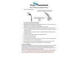
T90sr
electric shower
! IMPORTANT !
Under *NO circumstances should
this shower be connected directly
to a mains water supply.
It is designed for GRAVITY FED
COLD WATER systems ONLY !
*Failure to comply WILL invalidate product warranty
European Union Registered Design No. 003154467-0003/0004
The showerhead and hose supplied with this product are a safety
critical part of your shower. Failure to use genuine Triton parts
may cause injury and invalidate your guarantee.

2
Products manufactured by Triton are safe and without risk provided they are
installed, used and maintained in good working order in accordance with our
instructions and recommendations.
WARNING: DO NOT operate shower if frozen, or suspected of being frozen.
It must thaw out before using.
DO NOT operate the unit if the showerhead or spray hose becomes damaged.
DO NOT restrict ow out of shower by placing showerhead in direct contact
with your body.
DO NOT operate the shower if water ceases to ow during use or if water has
entered inside the unit because of an incorrectly tted cover.
WARNING: If restarting the shower immediately after stopping, be aware
that a slug of hot water will be expelled for the rst few seconds.
The spray head must be descaled regularly.
Fit only shower heads recommended by the manufacturer and never t any
additional device to restrict the water outlet ow.
The outlet must not be connected to any tap or tting other than those specied.
This appliance is intended to be permanently connected to the water mains and
not connected by a hose set.
A suitable double pole isolation switch for supply disconnections must be
incorporated in the xed wiring circuit in accordance with current wiring rules.
See Electrical Installation section for further details.
Supply pressure - see page 11
This book contains all the necessary tting and operating instructions for
your electric shower.
Care taken during the installation will provide a long, trouble-free life from
your shower.
PLEASE READ THIS IMPORTANT SAFETY INFORMATION
INTRODUCTION - PLEASE READ
WARNING
This appliance can be used by children aged from 3 years and
above and persons with reduced physical, sensory or mental
capabilities or lack of experience and knowledge if they have
been given supervision or instruction concerning use of the
appliance in a safe way and understand the hazards involved.
Children may not play with the appliance. Cleaning and user
maintenance shall not be made by children.

3
Products manufactured by Triton are safe and without risk provided they are installed, used and
maintained in good working order in accordance with our instructions and recommendations.
WARNING: DO NOT operate shower if frozen, or suspected of being frozen. It must thaw out
before using.
DO NOT operate the unit if the showerhead or spray hose becomes damaged.
DO NOT restrict ow out of shower by placing showerhead in direct contact with your body.
DO NOT operate the shower if water ceases to ow during use or if water has entered inside
the unit because of an incorrectly tted cover.
WARNING: If restarting the shower immediately after stopping, be aware that a slug of
hot water will be expelled for the rst few seconds.
PLEASE READ THIS IMPORTANT SAFETY INFORMATION
1 GENERAL
1.1 Isolate the electrical and water supplies before
removing the cover.
1.2 Read all of these instructions and retain them
for later use.
1.3 DO NOT take risks with plumbing or electrical
equipment.
1.4 Isolate electrical and water supplies before
proceeding with the installation.
1.5 The unit must be mounted onto the nished
wall surface (on top of the tiles). DO NOT tile
up to or seal around ANY PART of the unit
using silicone sealer after xing to the wall.
Special care must be taken NOT TO BLOCK
OR SEAL ANY PRD VENTS ON THE UNIT.
1.6 Contact Customer Service (see back page), if
any of the following occur:
a) If it is intended to operate the shower at
pressures above the maximum or below the
minimum stated.
b) If the unit shows a distinct change in performance.
c) If the shower is frozen.
1.7 If it is intended to operate the shower in areas
of hard water (above 200 ppm temporary
hardness), a scale inhibitor may have to be
tted. For advice on the Scale Inhibitor,
contact Customer Service.
1.8 The showerhead must be cleaned regularly
with descalent to remove scale and debris,
otherwise restrictions to the ow on the outlet
of the unit will result in higher temperatures
and could also cause the (PRD) Pressure Relief
Device in the unit to operate.
1.9 This product is not suitable for mounting into
steam rooms or steam cubicles.
2
PLUMBING
2.1 The plumbing installation must comply with
Water Regulations, Building Regulations or any
particular regulations as specied by Local
Water Company or Water Undertakers and
should be in accordance with BS EN 806.
2.2 The supply pipe must be ushed to clear debris
before connecting to the shower unit.
2.3 DO NOT solder pipes or ttings within 300mm
of the shower unit, as heat can transfer along
the pipework and damage components.
2.4 DO NOT t any form of outlet ow control as
the outlet acts as a vent for the heater can.
2.5 DO NOT use excessive force when making
connections to the exible hose or
showerhead, nger tight is sufcient.
2.6 All plumbing connections must be completed
before making the electrical connections.
2.7 This appliance MUST NOT be connected to
the inlet supply by a hose-set.
3
ELECTRICAL
3.1 The installation must comply with BS 7671
‘Requirements for electrical installations’ (IEE
wiring regulations), building regulations or any
particular regulations as specied by the local
Electrical Supply Company.
3.2 This appliance MUST be earthed.
3.3 In accordance with ‘The Plugs and Sockets etc.
(Safety) Regulations 1994’, this appliance is
intended to be permanently connected to the
xed wiring of the electrical mains system.
3.4 Make sure all electrical connections are tight to
prevent overheating.
3.5 A 30mA residual current device (RCD) MUST
be installed in all UK electric and pumped
shower circuits. This may be part of the
consumer unit or a separate unit.
3.6 Switch off immediately at isolating switch if
water ceases to ow during use.
3.7 Other electrical equipment i.e. extractor fans,
pumps must not be connected to the circuits
within the unit.
3.8 Switch off at isolating switch when not in use.
This is a safety procedure recommended with
all electrical appliances.
3.9 As with all electrical appliances it is
recommended to have the shower and
installation checked at least every two years by
a competent electrician to ensure there is no
deterioration due to age and usage.
IMPORTANT - PLEASE READ THESE
GENERAL GUIDANCE NOTES BEFORE PROCEEDING

4
GENERAL ADVICE TO USERS
The following points will help you understand
how the shower operates:
a. The electric heating elements operate at a
constant rate at your chosen power setting.
It is the rate of the water passing through
the heater can which determines the water
temperature. The slower the flow, the hotter
the water becomes; the faster the flow, the
cooler the water.
b. During winter, the water supply will be cooler
than in the summer. The flow rate will vary
between seasons at any one temperature
setting. At different times of the year you
may have to adjust the position of the
temperature control to maintain your desired
temperature setting.
NOTE: If ever the water becomes too hot and
you cannot obtain cooler water, first check
that the sprayplate in the showerhead has not
become blocked.
DO NOT place items such as soap or shampoo
bottles on top of the unit. Liquid could seep
through the joint between the cover and backplate.
ADVISORY - CLEANING
It is recommended that all products
are cleaned using warm, soapy water.
DO NOT use abrasive or aggressive
chemical cleaning products as this may
affect the product surface nish and
invalidate your guarantee.
IMPORTANT ADVICE TO USERS
COMMISSIONING ADVICE
When first installed the unit will be empty.
It is essential the unit should contain water
before the elements are switched on. It is
vital that the commissioning procedure
is followed. Failure to carry out this
operation will result in damage to the unit
and will invalidate the guarantee.
Please read this book thoroughly and familiarise yourself with all instructions before
commencing installation and keep it for future reference
The shower installation MUST be carried out by a suitably qualified person, in the sequence of
this instruction book.

5
Check that the water supply will satisfy requirements .............................................. 1
Check that water & cable entry points of the unit meet requirements ..................... 2
Check that the electric supply will satisfy requirements ............................................ 3
Siting of the shower ................................................................................................. 4
Plumbing installation ............................................................................................... 5
Electrical installation ................................................................................................ 6
Fit to the wall & connect the shower supplies .......................................................... 7
Installation ............................................................................................................... 8
ONLY Commission the shower in the way described ............................................ 9
Familiarise yourself with the user operating instructions ........................................... 10
1
2
3
4
5
6
7
8
9
10
Tick off as
you complete
PLEASE USE THE FOLLOWING CHECK LIST TO AID YOUR INSTALLATION
Triton recommend watching the short online *videos that cover electric shower basics before your
installation - *(videos may not show the exact model purchased).
• What is an electric shower?
• Electrical requirements for electric showers
• Plumbing requirements for electric showers
• Kilowatt ratings explained
To view these videos visit: www.tritonshowers.co.uk/triton-products/product-videos.aspx
SECTION
SECTION
SECTION
SECTION
SECTION
SECTION
SECTION
SECTION
SECTION
SECTION

6
To check the product suitability for commercial and multiple installations, please contact Triton’s
specication advisory service before installation. Please see back of book for contact information.
CONTENTS Page
INTRODUCTION
IMPORTANT SAFETY INFORMATION & GENERAL GUIDANCE NOTES (please read)
GENERAL ADVICE TO USERS - CLEANING ADVICE
INSTALLATION CHECK LIST (PLEASE FOLLOW & COMPLETE)
SPECIFICATIONS ...................................................................................................... 7
DIMENSIONS & CABLE/WATER ENTRY POINTS ....................................................... 8
ELECTRICAL REQUIREMENTS ............................................................................ 9 - 10
INSTALLING THE SHOWER ................................................................... 11 - 20
Siting of the shower ................................................................................... 11 - 12
Plumbing installation ......................................................................................... 13
Electrical installation .......................................................................................... 14
Fit to the wall & connect the shower supplies ............................................. 14 - 16
Installation ................................................................................................. 17 - 18
COMMISSIONING PROCEDURE ........................................................19 - 20
USER OPERATING INSTRUCTIONS & FUNCTIONS .......................................... 21 - 23
Cleaning the filter - installers & service engineers only ........................................... 24
Fault finding/Troubleshooting ......................................................................... 25 - 26
Spare parts ...................................................................................................... 27- 28
SHOWER CONTROLS - QUICK USER GUIDE .................................................29
Service Policy/Guarantee ........................................................................... Rear cover

7
SPECIFICATIONS
check list
ELECTRICAL
Nominal power - rating at 230V -
9.0kW – (40A MCB rating)
PLUMBING (see page 11 & 12 for water regulations)
Supply Source - see page 11 for full details Cold water storage ONLY
Minimum capacity 114 litres (25 gallons)
Minimum head height = 8cm
Maximum head height = 10m
Minimum flow to shower inlet = 8l per minute
Maximum inlet temperature 28°C
Minimum inlet temperature 2°C
Inlet connection 15mm diameter
Outlet connection ½” BSP male thread
MATERIALS
ABS Backplate, cover, controls, showerhead
Acetal Sprayplate
Minerally insulated corrosion resistant metal
sheathing
Elements
STANDARDS and APPROVALS
Splashproof rating IP25
Safety Complies with the requirements of current
British and European safety standards for
household and similar electrical appliances
BEAB Complies with requirements of the British
Electrotechnical Approvals Board (BEAB)
CE Meets with Compliance with European
Community Directives (CE)
1
SECTION

8
DIMENSIONS & ENTRY POINTS
2
check list
SECTION
Fig.2
Fig.1
ENTRY POINTS
DIMENSIONS
CABLE
Left: Bottom, Back & Top.
= Back
= Others
322mm 95mm
266mm
WATER
Left: Bottom, Back & Top.
= Back
= Others
PLEASE NOTE: Deviation from the
approved entry points will invalidate
product specifications and warranty.

9
ELECTRICAL REQUIREMENTS
3
check list
SECTION
W-006-A
WARNING!
THIS APPLIANCE MUST BE EARTHED
Meter
Incoming
supply
fuse
Meter
tails
Consumer
unit
Pull cord
isolating switch
Shower
unit
Fuse or
MCB
RCD
(can be part of
consumer unit)
80A or 100A
main switch
Table A
MCB
30/32A
32A
40A
40A
40A
40/45A
45A
cartridge
fuse
30A
35A
35A
45A
45A
45A
45A
unit
rating
7.0kW
7.5kW
8.0kW
8.5kW
9.0kW
9.5kW
10.5kW
CIRCUIT PROTECTION
Fig.4 Schematic of installation circuit
ELECTRICAL REQUIREMENTS
The installation, supply cable and circuit
protection must conform with BS 7671 (IEE
wiring regulations) and be sufcient for the
amperage required.
The following notes are for guidance only:
1 The shower must only be connected to a
230-240V ac supply. If you are installing a
shower with a kilowatt rating above 9kW, it
is advisable to contact the local electricity
supply company.
1.1 The electrical rating of the shower is shown
on the rating label (Fig.3) within the unit.
2 Before making any sort of electrical
connection within the installation make
sure that no terminal is live. If in any doubt,
switch off the whole installation at the mains
supply and remove the correct fuse.
3 The shower must be connected to its own
independent electrical circuit. IT MUST NOT
be connected to a ring main, spur, socket
outlet, lighting circuit or cooker circuit.
3.1 The electrical supply must be adequate for
the loading of the unit and existing circuits.
4 Check your consumer unit (main fuse box)
has a main switch rating of 80A or above
and that it has a spare fuse way which will
take the fuse or Miniature Circuit Breaker
(MCB) necessary for the shower (Fig.4).
4.1 If your consumer unit has a rating below
80A or if there is no spare fuse way, then the
installation will not be straightforward and
may require a new consumer unit serving
the house or just the shower.
4.2 You will need to contact the local electricity
company. They will check the supply and
carry out what is necessary.
5 For close circuit protection DO NOT use a
rewireable fuse. Instead use a suitably rated
Miniature Circuit Breaker (MCB) or cartridge
fuse (see Table A).
5.1 A 30mA residual current device (RCD)
MUST be installed in all UK electric and
pumped shower circuits. This may be part of
the consumer unit or a separate unit.
Triton Showers,
Triton Road, Nuneaton,
Warwickshire, CV11 4NR
xxxx
Fig.3

10
ELECTRICAL REQUIREMENTS
3
check list
SECTION
Table B
Note: Cable selection is dependent on
deratin
g
factors
Twin and earth PVC insulated cable
Current carrying capacity
In conduit
trunking
6mm²
38A
10mm²
52A
16mm²
69A
Installed in an
insulated wall
6mm²
32A
10mm²
43A
16mm²
57A
Clipped direct
or buried in a
non-insulated
wall
6mm²
46A
10mm²
63A
16mm²
85A
6mm
2
10mm
2
16mm
2
*The method below may be used by
installers to determine the approximate
size of the incoming cable.
1. Measure the width of an individual strand,
and half that measurment to find (r),
e.g: 1.34mm ÷ 2 = (r) 0.67mm
2. Multiply (r) x (r) x 3.14,
e.g: (r) 0.67 x (r) 0.67 x 3.14 = 1.41mm
2
3. Multiply this by the number of wire strands
(usually 7), e.g: 1.41mm
2
x 7 = 9.87mm
2
.
4. The number obtained would suggest
10mm
2
wiring.
*PLEASE NOTE: If unsure, consult a qualified Electrician.
6 A 45 amp double pole isolating switch with
a minimum contact gap of 3 mm in both
poles must be incorporated in the circuit.
6.1 It must have a mechanical indicator showing
when the switch is in the OFF position, and
the wiring must be connected to the switch
without the use of a plug or socket outlet.
6.2 The switch must be accessible and clearly
able, but out of reach of a person
u
xed bath or shower, except for the
cord of a cord operated switch, and should
be placed so that it is not possible to touch
the switch body while standing in a bath or
shower cubicle. It should be readily accessible
to switch off after using the shower.
7 Where shower cubicles are located in any
rooms other than bathrooms, all socket
outlets in those rooms must be protected by
a 30mA RCD.
8 The current carrying capacity of the cable
must be at least that of the shower circuit
protection (see Table B).
8.1 To obtain full advantage of the power
provided by the shower, use the shortest
cable route possible from the consumer unit
to the shower.
8.2 It is also necessary to satisfy the disconnection
time and thermal constraints which means
that for any given combination of current
demand, voltage drop and cable size, there is
a maximum permissible circuit length.
9 The shower circuit should be separated from
other circuits by at least twice the diameter
of the cable or conduit.
9.1 The current rating will be reduced if the
cabling is bunched with others, surrounded
by thermal loft or wall insulation or placed
in areas where the ambient temperature
is above 30°C. Under these conditions,
derating factors apply and it is necessary to
select a larger cable size.
9.2 In the majority of installations (see
Table B), the cable will unavoidably be
placed in one or more of the above
conditions. This being so, it is strongly
recommended to use a minimum of 10mm
cabling throughout the shower installation.
9.3 In any event, it is essential that individual
site conditions are assessed by a competent
electrician in order to determine the correct
cable size and permissible circuit length.

11
SITING OF THE SHOWER
SITING OF THE SHOWER
The installation must be in accordance with
Water Regulations/Bylaws - see page 7 and
below for water specifications.
• To ensure activation of the heating elements,
the shower must be connected to a cold
water supply which is gravity fed from a
static cold water storage cistern with a
minimum capacity of 114 litres (25 gallons)
that will deliver a MINIMUM of 8 litres per
minute to the shower water inlet.
• There must be a maximum head of water of
10 metres and a minimum head of 8 cm as
measured between the bottom of the cistern
and the top of the shower unit. There must
be no other cold water draw-offs between
the cistern and the unit and the pipe must
not supply water to any other tap or fitting
at a lower level.
• Pipework to the shower unit MUST be
routed where it remains below the level of
the water cistern.
• If it is intended to operate the shower at
pressures above the maximum or below the
minimum stated, contact Customer Service
for advice.
• If the stated flow rates are not available,
it may not be possible to achieve optimum
performance from the unit throughout
the year.
• During periods of high ambient temperatures
it may be necessary to select the economy
power setting to achieve your preferred
shower temperature.
Fig.5 shows a typical system layout.
• Refer to fig.6 for the correct siting of the
shower. Position the unit where it will
NOT be in direct contact with water from
the showerhead. Position the shower unit
vertically.
• Allow enough room between the ceiling and
the shower to access the cover top screws.
• Mark out entry points and routing of the
water and electric supplies into the shower.
4
check list
SECTION
Mains
water
supply
Gate
valve
Stop
valve
Cold water
cistern
Mains electric supply
(via double pole switch)
Double
pole
isolating
switch
Separate permanently
connected supply
from consumer unit
Shower
unit
Minimum capacity
114 litres (25 gallons)
8 cm (3")
minimum
WARNING
UNDER NO CIRCUMSTANCES should
this shower be connected directly to
the mains water supply.
Diagrammatic view (not to scale)
Fig.5
ADVISORY NOTE
The supply pipe from the cistern should be
on the opposite side to the oat operated
valve to prevent air being drawn into the
pipe when the cistern is lling.
If it is intended to operate the shower in
hard water areas (above 200 ppm temporary
hardness) a scale inhibitor should be tted.

12
WARNING
The shower MUST NOT be
positioned where it will be
subjected to freezing conditions.
IMPORTANT: Water regulations (fig.6)
• It is required that the showerhead be
‘constrained by a fixed or sliding attachment
so that it can only discharge water at a point
not less than 25mm above the spill-over level
of the relevant bath, shower tray or other
fixed appliance’.
• If the riser kit is supplied with a ‘soap dish
hose retainer’ or bespoke ‘hose retainer’, it
will in most cases meet this requirement. If
the showerhead can still be placed within a
bath, basin or shower tray within the 25mm
limit, then a double check valve, or similar
MUST be fitted in the supply pipework to
prevent back-flow.
Pressure relief safety device
• A pressure relief device (PRD) is designed
into the shower unit which complies with
European standards. The PRD provides a level
of appliance protection should an excessive
build up of pressure occur within the shower.
DO NOT operate the shower with a damaged or
kinked shower hose, or a blocked showerhead.
This may cause the PRD to operate.
• When commissioning, the showerhead
must be removed from the flexible hose.
Failure to follow this procedure may cause
the PRD to operate.
• Make sure the shower is positioned over a
bath or shower tray. If the PRD operates,
then water will eject from the bottom of
the unit. Should this happen, turn off the
electricity and water supplies to the shower
at the isolating switch and stop valve.
Contact Customer Service for advice on
replacing the PRD.
SITING OF THE SHOWER
4
check list
SECTION
IMPORTANT: The unit must be mounted on
a flat surface which covers the full width and
length of the backplate. It is important that
the wall surface is flat otherwise difficulty
may be encountered when fitting the cover
and subsequent operation of the unit may
be impaired.
IMPORTANT: If installing onto a tiled wall,
ALWAYS mount the unit on the surface of
the tiles. NEVER tile up to the unit.
Cold water supply
from cistern
(top, bottom or back)
Ceiling
Shower unit
must not
be within
an area
1 metre
from base
Height of
showerhead
and shower
to suit user's
requirement
Spillover
level
25 mm minimum
Shower unit can
be mounted either
side of riser rail
Outline of bath
or shower tray
Fig.6
*(diagrammatic view – not to scale)

13
PLUMBING INSTALLATION
PLUMBING INSTALLATION
Plumbing to be carried out before wiring
• DO NOT use jointing compounds on any
pipe fittings for the installation.
• DO NOT solder fittings near the shower unit
as heat can transfer along the pipework and
damage components.
• Compression fittings MUST be used to
connect to the inlet of the shower (fig.7).
Push-on fittings must NOT be used as full
engagement cannot be guaranteed.
• If installing a feed pipe from the back or
bottom, the centre of the inlet valve to the
wall surface is 21mm (fig.7).
NOTE: If entry is from the back, the nut of the
compression fitting will be partially behind the
surface of the wall. This area MUST be left clear
when plastering and tiling around the pipework
in order to make the nut accessible for future
adjustments (fig.7).
NOTE: A fullway isolating valve (complying with
Water Regulations) must be fitted in the water
supply to the shower as an independent means
of isolating the water supply should maintenance
or servicing be necessary.
IMPORTANT: Before completing the connection
of the water supply to the inlet of the shower, flush
out the pipework to remove all swarf and system
debris. This can be achieved by connecting a hose
to the pipework and turning on the water supply
long enough to clear the debris to waste.
IMPORTANT: A suitable sealant should always
be used to seal around the incoming pipework to
prevent water entering the wall.
IMPORTANT INFORMATION
The outlet of the shower acts as a vent
and must not be connected to anything
other than the hose and showerhead
supplied.
Fig.7
5
check list
SECTION
21mm

14
Installation -
FIT TO THE WALL & CONNECT THE SHOWER SUPPLIES
ELECTRICAL INSTALLATION
IMPORTANT: Switch off the electricity supply at
the mains before proceeding.
• The supply cable MUST be secured either by
routing through conduit, in trunking or by
embedding in the wall, in accordance with
IEE regulations.
NOTE: Conduit entry can only be from rear.
ELECTRICAL INSTALLATION
NOTE: Deviations from the designated entry
points will invalidate product approvals. The
cable entry points are listed on page 8.
• Seal around rear entry cable to prevent water
ingress into the wall.
FIT TO THE WALL & CONNECT THE
SHOWER SUPPLIES
The top of the shower backplate has been
designed with a removable pipe/electric entry
point trim that may be cut as shown in fig.8 to
accommodate either pipe or electric cable entry.
The bottom trimplate has a ‘cut out’ access point
for pipe/electric.
• Decide on the pipe and electric entry
required.
• Once chosen, remove either the top trim or
appropriate ‘cut out’ section using a junior
hacksaw and file or suitable knife.
6
check list
7
check list
SECTION
SECTION
*PLEASE NOTE: The 'cut out' is NOT designed
to 'snap out'. ONLY a junior hacksaw, file or suitable
knife should be used. Excessive damage to
the lower trimplate may invalidate product
specifications and warranty.
Fig.8
Top pipe/electric
entry point trim
‘Cut out’
entry point*
Trim may be cut to
t either pipe or
electric entry
WARNING
Check there are no hidden cables or
pipes before drilling holes for wall plugs.
Use great care when using power tools near
water. The use of a residual current device
(RCD) is recommended when
using power tools.

15
Fitting Procedure
• Turn off water supply at the isolating stop
valve.
• Temporarily connect the water supply to the
inlet of the shower using a 15mm x 15mm
compression fitting.
• Use the backplate as a template making sure
it is level and mark the fixing holes (fig.9).
• Remove the unit from the wall. Drill and
plug the wall. An appropriate drill bit should
be used. If the wall is plasterboard or a soft
building block, appropriate wall plugs should
be fitted.
• Screw the top middle (no2) fixing screw into
position leaving the base of the screw head
protruding 6mm out from the wall.
• Hook the backplate over the top screw and
fit the other fixing screws into position, but
DO NOT fully tighten the screws at this
stage as the fixing holes are elongated to
allow for out of square adjustment after the
plumbing connection has been completed.
• Connect the water supply to the inlet DO
NOT use excessive force when making the
connection.
• Make sure the backplate is square on the
wall and tighten the retaining screws which
hold it in place.
• Turn on the water supply and check for leaks
in the pipework connection to the shower.
IMPORTANT: A temporary locking screw is
fitted to the power selector spindle at the factory
(fig.10). This is to make sure the spindle is held
in the COLD position whilst the commissioning
procedure is carried out.
DO NOT remove the locking screw before
the commissioning procedure has been
successfully completed.
FIT TO THE WALL & CONNECT THE SHOWER SUPPLIES
7
check list
SECTION
Fig.9
Fig.10
4
1
3
5
2
ONLY remove locking
screw after commissioning
has been successfully
completed
power
selector
spindle
Spindle
marker
set on
COLD

16
NOTE: At this stage no water can flow through
the unit.
IMPORTANT: A suitable sealant should always
be used to seal around the incoming pipework to
prevent water entering the wall.
• Route the cable into the shower unit for
connection to the terminal block (fig.11)
as follows:
Live cable to terminal marked L
Earth cable to terminal marked
Neutral cable to terminal marked N
• Fig.12 shows a schematic wiring diagram.
IMPORTANT: When connecting the cable fully
tighten the terminal block screws and make sure
that no cable insulation is trapped under the
screws. Loose connections can result in cable
overheating.
NOTE: The supply cable earth conductor must
be sleeved. The outer sheath of the supply cable
must be stripped back to the minimum.
• The use of connections within the unit or
other points in the shower circuit to supply
power to other equipment i.e. extractor fans,
pumps, etc. will invalidate the guarantee.
• DO NOT switch on the electricity supply
until the shower cover has been fitted.
FIT TO THE WALL & CONNECT THE SHOWER SUPPLIES
7
check list
SECTION
Fig.11
1. Terminal block
2. Solenoid valve
3. Thermal cut-out (main)
4. Start/Stop button
5. Motor Power Supply
L
N
E
L
+ -
N
M
1
4
5
6
8
7 7
3
inlet
outlet
2
9
6. Pump and motor assembly
7. Selector microswitches
8. LED indicator
9. Heater Can Elements
Fig.12

17
INSTALLATION
OFF
ON
COMMISSION
OFF
ON
COMMISSION
8
check list
SECTION
TO DO BEFORE FITTING THE COVER
1. Make sure the water supply is turned on to
the shower.
2. Open the bleed screw on the pump unit
(fig.13) by rotating two revolutions. When
water flows from the opening, this indicates
that any trapped air is vented and that the
pump unit is primed. The bleed valve MUST
now be closed by rotating in the opposite
direction.
3. Make sure the temporary locking screw on
the power selector is in place - see fig.10.
Fig.13
Fig.14
Commission ON
= Pump OFF
Bleed screw
Open
Commission OFF
= Pump ON
WARNING
Before tting the cover the following
list MUST be checked to ensure the
commissioning procedure may be
carried out correctly.

18
INSTALLATION
8
check list
SECTION
4. IMPORTANT: Make sure the commission link
is in the ON position - see fig.14.
NOTE: With the commission link in the
ON position the pump is OFF and will not
operate.
FITTING THE COVER
5. Locate the trimplate into the backplate.
6. Turn the temperature control spindle
ANTI-CLOCKWISE until it stops (fig.15).
7. The power selector knob must be aligned as
shown, to the COLD position (fig.16).
8. Turn the temperature control knob fully
ANTI-CLOCKWISE until it stops (fig.16).
9. Clip the LED into the holder on the back of
the ‘power on’ lens.
10. Check to ensure that the wiring is not
trapped and replace the cover squarely to
the backplate and guide into position so that
the knobs locate correctly into the splined
spindles.
Should any difficulty arise, recheck the
points above.
11. While applying slight pressure to the cover,
secure in position with the retaining screws.
12. Fit the riser rail and kit (see kit
instructions).
NOTE: The knobs should be left in these
positions ready for commissioning.
Fig.16
COLD
position
Fully anti-clockwise
position
POWER
SELECTOR
KNOB
TEMPERATURE
CONTROL
KNOB
Fig.15
Turn the
spindle until
it stops
WARNING
COVER RETAINING SCREWS
ONLY the SUPPLIED SCREWS should be
used. The use of none supplied screws WILL
invalidate product specications & warranty.

19
COMMISSIONING PROCEDURE
The first operation of the shower is intended
to flush out any remaining unit debris and
to make sure the heater unit contains water
before the elements are switched on.
This operation MUST be carried out WITH
the flexible hose screwed to the outlet but
WITHOUT THE SHOWERHEAD ATTACHED.
Make sure the outlet of the flexible hose is
directed to waste.
1. Before turning on the electric supply to the
shower, make sure that the power selector is
at the ‘COLD‘ position and the temperature
control is turned to fully anti-clockwise to
‘MAXIMUM’ flow (fig.17).
2. Turn on the electric supply to the shower at
the isolating switch.
3. Press the Start/Stop button and wait until
water starts to flow from the flexible hose. At
least 30 seconds
4. Once flushing out has been completed, stop
the water flow by pressing the Start/Stop
button.
WARNING
Before normal operation of the shower, it
is essential the following commissioning
procedure is completed correctly.
COMMISSIONING
9
check list
SECTION
PLEASE NOTE: On the COLD power
setting (only) the TEMPERATURE
selector settings are as follows:
Fully anti-clockwise = maximum ow
Fully clockwise = minimum ow
Fig.17
COLD
position
Fully anti-clockwise
position
POWER
SELECTOR
KNOB
TEMPERATURE
CONTROL
KNOB

20
COMMISSIONING
9
check list
SECTION
SWITCH OFF THE ELECTRICITY SUPPLY TO THE
SHOWER AT THE ISOLATING SWITCH BEFORE
PROCEEDING TO STAGE 5.
5. Unscrew the cover retaining screws and lift the
cover from the backplate.
6. Make sure the commission link is moved to the
OFF position - see fig.14.
NOTE: With the commission link in the OFF
position the pump is ON and will operate
normally.
7. Remove the locking screw from the power
selector spindle (fig.18) and store for future
use. Make sure the selector spindle is left at the
same position.
8. Check to ensure that the wiring is not trapped
and replace the cover squarely to the backplate
and guide into position so that the knobs
locate correctly into the splined spindles.
Should any difficulty arise, recheck the
points above.
9. While applying slight pressure to the cover,
secure in position with the retaining screws.
Fit the showerhead to the flexible hose and
place in the showerhead holder.
The shower is now ready for normal operation.
Fig.18
Remove locking screw
after commissioning
has been successfully
completed
power
selector
spindle
Spindle
marker
set on
COLD
/