Marley Engineered Products 761 User manual
- Category
- Household fans
- Type
- User manual

READ AND SAVE THESE INSTRUCTIONS
MODELS 761, 763, 765, 7100, 7130, 7150,
8090 & 8100 FANS
MODELS 768IC, 770IC, 7100L, 7150L, 7100FL, 7150FL,
8090L & 8100L FAN/LIGHTS
MODELS 7100H, 7100FLH, 7150H & 7150FLH
FANS & FAN/LIGHTS with HUMIDITY SENSOR
DESCRIPTION
The FAN and FAN/LIGHT models listed in these instructions
are intended for use in bathrooms. However, they can also be
used in other areas where ventilation is required. These units
are approved for installation in the ceiling above a bathtub or
shower stall only when connected to a U.L. Listed GFCI pro-
tected branch circuit. ALL FAN/LIGHT models are U.L. Listed
Type I.C. (Inherently Protected) for installation in insulated ceil-
ings.
UNPACKING
Unpack carefully. If there are missing components or hidden
damage, immediately contact your distributor or the delivering
carrier concerning discrepancies.
IMPORTANT SAFETY INSTRUCTIONS
WARNING:
TO REDUCE RISK OF FIRE, ELECTRICAL SHOCK OR
INJURY TO PERSONS, OBSERVE THE FOLLOWING:
1. Do not use this fan with any Solid-State speed control
device.
2. Use this unit only in the manner intended by the manufa-
cturer. If you have any questions, contact the
manufacturer.
3. Before servicing or cleaning unit, switch power off at
service panel and lock service panel to prevent power
from being switched on accidentally.
4. Installation work and electrical wiring must be done by
qualified person(s) in accordance with all applicable
codes and standards, including fire-rated construction.
5. Sufficient air is needed for proper combustion and
exhausting of gases through the flue (chimney) of fuel
burning equipment to prevent back drafting. Follow the
heating equipment manufacturer’s guideline and safety
standards such as those published by the
National Fire Protection Association (NFPA), and the
American Society for Heating and Air Conditioning
Engineers (ASHRAE), and the local code authorities.
6. When cutting or drilling into wall or ceiling, do not damage
electrical wiring or other hidden utilities.
7. Ducted fans must always be vented to the outdoors.
8. If this unit is installed over a tub or shower, it must be
marked as appropriate for the application. See product
label.
9. NEVER place a switch where it can be reached from a tub
or shower.
10. CAUTION: For General Ventilation Use Only! Do not
use to exhaust hazardous or explosive materials or vapors.
11. Not for use in kitchens.
TOOLS
Installation of your Marley Engineered Products fan is easy. No
special technical knowledge is needed; only a few ordinary
tools are required:
Screwdriver
Hammer
Saber saw, Keyhole saw, or Jig saw
Electric drill with bit
Wire cutters
Wire stripper
Wire nuts and general electrical supplies
Safety glasses
Ruler and straight edge
All hand tools should be insulated. Power tools should display
the UL Listing Mark.
Page is loading ...

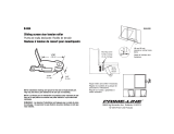
NEW HOME INSTALLATION
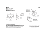
MODELS 761, 763, 765, 768IC, AND 770IC
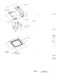
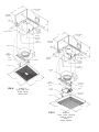
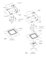
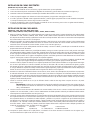
NOTE: Plastic scroll and motor assembly can be removed from
the metal housing prior to step one if desired. Simply loosen four
mounting screws securing scroll to housing and slide it towards
the outlet box. Carefully lift and tilt scroll, motor and wheel assem-
bly to remove it from housing. (See Fig. 1 & 2.)
1. Pull motor plug from receptacle. Remove outlet box cover and
desired knockout from housing.
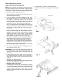
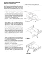
2. If the duct adapter is attached, disregard this note. Attach
duct adapter to housing by first hooking mounting flange
over edge of air discharge opening. Pivot duct adapter
insuring (2) aligning tabs are inside opening and align (2)
locking tabs with small rectangular holes. Press firmly into
holes to lock. See Fig. 3. Remove tape securing damper.
NOTE: The attachment of the duct adapter to the housing may
be reinforced if desired, by installing a #8AB screw through the
oblong hole in the duct adapter and the small round hole in
the housing.
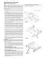
3. Insert mounting brackets with angle pointing away from
housing. Position housing into ceiling location. Housing is
stamped to show a line at 3/8” for drywall and 3/4” for standard
sheetrock and plaster. Fasten securely through mounting
holes provided in housing. (Fig. 4.) Pull mounting brackets
against adjacent ceiling joist and fasten securely. (Fig. 5.)
4. Run 120vAC, 60 Hz power cables from wall switch/switches to
appropriate knockout in housing. Use a BX or Romex con-
nector. (Refer to wiring diagram designated for the model
being installed.) Connect cables from wall switch/switches to
receptacle wires using approved wire connectors. Connect
ground wire to green screw or lead in outlet box. Install outlet
box cover and secure with screw provided.
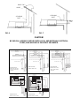
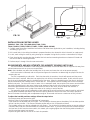
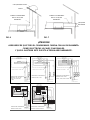
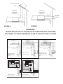
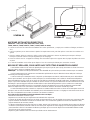
5. Run four inch round duct from fan air discharge outlet to wall
cap or roof cap. See Figs. 6 & 7.
IMPORTANT: Be sure nothing obstructs the discharge of the fan.
Take precautions to insure that insulation does not get into
duct work or fan discharge opening, and damper opens and
closes freely.
6. Carefully replace plastic scroll, motor and wheel assembly if
unit was disassembled for installation. Reverse procedure as
noted. Tighten screws securely and push plug into motor
receptacle.
7. (MODELS 761, 763 & 765 ONLY)
Squeeze springs on grille and insert in tabs located in housing.
See Fig. 1. Press grille firmly into place.
8. (MODELS 768IC & 770IC ONLY)
Center reflector in center of grille. Push light plug into recepta-
cle. Center reflector/grille assembly over housing and engage
1” mounting bolt through center hole in reflector into metal
mounting bracket located on plastic scroll and motor
assembly. Tighten bolt until grille is firmly pulled against the
ceiling. See Fig. 2.
9. Install light bulb. (Type A-19, 100 watts maximum.)
10. Install the snap-on lens by engaging lens tabs into grille
slots.
FIG. 3
FIG. 4
FIG. 5
LOCKING
TABS
MOUNTING
FLANGE
DUCT ADAPTER
ALIGNING

FIG. 6
FIG. 7
CAUTION!
BE SURE ALL WIRING COMPLIES WITH LOCAL AND NATIONAL ELECTRICAL
CODES, AND HOUSING IS PROPERLY GROUNDED.
ROOF CAP
WALL
CAP
4” ROUND
DUCT
4” ROUND
DUCT
ROOF
OUTLET BOX
RECEPTACLE
WIRING DIAGRAM
MODELS 768IC, 770IC
LIGHT
GREEN
WHITE
WHITE
WHITE
GREEN
BLACK
WIRING DIAGRAM
MODELS 7100H, 7150H
SENSOR
TIMER
BLACK
WHITE
WHITE
WHITE
WIRING DIAGRAM
MODELS 7100L, 7150L,
7100FL, 7150FL, 8090L
AND 8100L
LIGHT
NIGHT LIGHT
BLUE
BROWN
WHITE
WHITE
WHITE
WHITE
BLACK
WIRING DIAGRAM
MODELS 7100FLH, 7150FLH
LIGHT
BALLAST
BALLAST
LIGHT
NIGHT LIGHT
BLU
BLU
BROWN
VENTILATOR
BLACK
WHITE
GROUND SCREW
GROUND
WHITE
BLACK
BLACK
WIRING DIAGRAM
MODELS 761, 763, 765
7100, 7130, 7150, 8090
AND 8100
WALL
SWITCH
WALL
SWITCH
WALL
SWITCH
WALL
SWITCH
WALL
SWITCH
WALL
SWITCH
120V AC
60 HZ
SUPPLY
OUTLET BOX
RECEPTACLE
VENTILATOR
GROUND SCREW
GROUND
WHITE
BLACK
BLACK
BLACK
120V AC
60 HZ
SUPPLY
OUTLET BOX
RECEPTACLE
VENTILATOR
GROUND SCREW
GROUND
WHITE
BLACK
BLACK
BLACK
BLACK
120V AC
60 HZ
SUPPLY
WALL
SWITCH
WALL
SWITCH
WALL
SWITCH
WALL
SWITCH
OUTLET BOX
VENTILATOR
TIMER
GROUND SCREW
GROUND
WHITE
BLACK
BLACK
120V AC
60 HZ
SUPPLY
OUTLET BOX
RECEPTACLE
VENTILATOR
SENSOR
GROUND SCREW
GROUND
WHITE
BLACK
BLACK
BLACK
BLACK
120V AC
60 HZ
SUPPLY
BLACK
WHITE
BLACK
WHITE

INSTALLATION IN EXISTING HOMES
(MODELS: 761, 763, 765, 768IC & 770IC)
1. Review the section: “New Home Installation” and follow instructions where applicable.
2. Refer to wiring diagrams for wiring and Fig. 6 & 7 for duct work.
3. Determine location of ventilator, remembering that the housing must be installed next to a joist.
4. Drill a small hole in ceiling in proposed location, then locate this hole in the attic.
5. In the attic, position housing against ceiling joist and over drilled hole. Using the housing as a template, mark ceiling for
cutout. Make cutout on this line.
6. Remainder of installation is the same as steps 1 through 10 under “New Home Installation” above. Cracks between
housing and ceiling may be plastered or caulked.
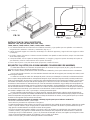
NEW HOME INSTALLATION
(MODELS: 7100, 7130, 7150, 8090, 8100, 7100L,
7150L, 7100H, 7100FLH, 7150H, 7150FLH, 7100FL, 7150FL, 8090L & 8100L)
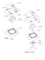
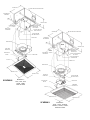
1. Remove grille assembly from carton and set aside until needed. Remove reflector assembly from blower unit
(MODELS: 7100L, 7100FLH, 7150FLH, 7150L, 7100FL, 7150FL, 8090L & 8100L) by pulling plug from receptacle,
loosen mounting screws and remove through keyhole slot. Pull timer plug from recetpacle if applicable. See Fig. 9.
2. Loosen three screws securing blower unit to housing and slide it toward outlet box. Carefully lift and tilt blower unit
and remove from housing. Pull motor plug from receptacle. Pull humidity sensor plug from recetpacle if
applicable. See Figs. 8 & 9.
3. Remove outlet box cover by removing mounting screw. Retain cover and screw for reinstallation. Remove desired
knockout from housing.
4. If DUCT ADAPTER is already attached to housing, disregard Item #4. If not proceed as follows! Attach DUCT
ADAPTER to housing by first hooking mounting flange over edge of air discharge opening. Pivot duct adapter
insuring (2) aligning tabs are inside opening and align (2) locking tabs with small rectangular holes. Press tabs
firmly into holes to lock. See Fig. 3. Remove tape securing damper.
NOTE: The attachment of the duct adapter to the housing may be reinforced, if desired, by
installing a #8AB screw through the oblong hole in the duct adapter and the small round
hole in the housing.
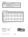
5. Insert (4) mounting brackets with angles pointing away from housing. In approximate location between joist where
housing will be located, drive (2) nails (4D or 6D) 1” from bottom of joist, 11” apart leaving 1/4” of nail projecting.
Position one set of mounting brackets over nails and drop into place. Extend the remaining mounting brackets to
the adjacent joist and repeat nailing procedure. Finish driving nails and adjust housing between ceiling joist.
See Fig. 10.
6. Run 120V A C, 60 Hz power cables from wall switch/switches to appropriate knockout in housing. Use a BX or
Romex connector. (Refer to wiring diagram designated for the model being installed.) Connect cables from wall
switch/switches to receptacle wires using approved wire connectors. Connect ground wire to green screw or lead
in outlet box. Install outlet box cover and secure with screw provided.
7. Run four inch duct from discharge outlet to roof jack or wall cap. See Figs. 6 & 7.
IMPORTANT: Be sure nothing obstructs the discharge of the vent. Take precautions to insure that
insulation does not get into ductwork or fan discharge opening, and damper opens and closes freely.
8. Push humidity sensor plug into receptacle, if applicable. Push blower motor plug into receptacle and carefully
replace blower unit. Reverse procedure as noted. Tighten screws securely. See Figs. 8 & 9.
9. Insert timer plug into humidity sensor receptacle, if applicable. Insert lamp plug of reflector assembly into lamp
receptacle on the outlet box. Align keyhole slot on reflector
assembly bracket over screw on blower unit and slide into place. Insure that protrusion in bracket aligns with hole
in blower assembly and tighten screw. Install 100 watt (maximum) type A-19 bulb and a 7 1/2 watt candelabra base
C-7 bulb. (MODELS: 7100L, 7150L, 8090L & 8100L only.) On fluorescent models 7100FL, 7150FL, 7100FLH and
7150FLH install two of the following 13 watt quad-tube compact fluorescent lamps / 2 Pin:
Osram/Sylvania Panasonic Philips General Electric
CF13DD/841 FQ13E41.u/2 PL-C13W/41/USA F13DBX23T4/SPX41
10.Squeeze spring on plastic grille and insert into tabs located in housing. See Figs. 8 & 9. Press grille firmly into place.

AIR DISCHARGE
OUTLET
OUTLET
BOX COVER
GRILLE
MOUNTING
TABS
BLOWER UNIT
GRILLE
12 1/2”
11 13/16”
7 5/8”
10”
11 1/2”
GRILLE
SPRING
BLOWER
MOUNTING
SCREWS
WIRE
CONNECTORS
HUMIDITY SENSOR
MODELS:
7100, 7130, 7150,
7100H, 7150H,
8090 & 8100
OUTLET
BOX COVER
GRILLE MOUNTING
TABS
BLOWER
UNIT
GRILLE
12 1/2”
12 1/2”
11 3/16”
7 5/8”
10”
GRILLE
SPRING
BLOWER
MOUNTING
SCREWS
REFLECTOR
MOUNTING
SCREW
REFLECTOR
ASSEMBLY
MODELS:
7100L, 7150L, 7100FLH,
7150FLH, 7100FL,
7150FL,
8090L & 8100L
FIG. 8
FIG. 9
MOUNTING
BRACKETS
MOUNTING
BRACKETS
WIRE
CONNECTOR
(PLUG)
WIRE
CONNECTOR
(PLUG)
TIMER
TIMER
HUMIDITY
SENSOR
AIR DISCHARGE
OUTLET
WIRE
CONNECTORS

INSTALLATION IN EXISTING HOMES
(MODELS: 7100, 7130, 7150, 8090, 8100, 7100L, 7150L,
7100H, 7100FLH, 7150H, 7150FLH, 7100FL, 7150FL, 8090L & 8100L)
1. Carefully read all previous installation instructions and follow those applicable to your installation, including ducting
and wiring. (Figs. 6 & 7.)
2. Drill a small hole in the ceiling from below in proposed location, then locate this hole in the attic (or crawl space).
3. In attic, mark ceiling for cutout by using housing as a template. Using this line, make a cutout about 1/4” larger.
4. Place housing with mounting brackets installed into hole and rest mounting brackets on sheetrock. Extend and
nail all four ends of mounting brackets.
5. Perform steps 1 through 10 as for new construction.
REQUIREMENTS AND ADJUSTMENTS FOR HUMIDITY SENSING UNITS ONLY
The unit should be mounted on a flat ceiling surface that does not exceed twelve feet in height and is away from
a direct heat source such as a room or sauna heater.
Note: Open windows may affect the humidity level in the room and cause the unit not to operate properly.
Once the location is selected, refer to the previous figures for instruction on determining the proper hole size for
mounting the unit.
The unit is operated by a wall switch. Each time the switch is turned on, the unit will operate until the preset
time on the timer is expired. After time has expired, the unit will be in the automatic mode. At this point the opera-
tion of the unit is dependent upon the humidity level of the room. When the humidity level of the room is above the
set-point selected on the humidity sensor, the unit will run. It will operate until the humidity level of the room drops
below its set-point. For the unit to come on when it is on automatic mode, the set-point of the sensor must be below
the existing humidity level in the room. It takes some amount of time for the unit to stop when the moisture is
removed or decreased and it also takes some amount of time for the unit to come on when the moisture is
increased. This prevents short cycling of the motor or its coming on and off too fast.
The automatic mode can be bypassed by simply switching the unit off and back on again through its wall switch.
This will allow immediate operation of the unit for the pre-set amount of time on the timer. the timer is preset for
about 15 minutes from factory with an adjustment range of 18 seconds minimum to a maximum of thirty minutes.
To adjust the humidity and time settings follow the steps below:
–Disconnect power and remove the grille
–Refer to Figure 11 for location and orientation of components
–Timer knob can be adjusted with your fingers. Turn clockwise to increase pre-set time delay. Full clockwise position
will set it to thirty minutes. Full counter clockwise position will set it to 18 seconds minimum.
–The humidity sensor can also be adjusted with your fingers. Turn shaft to full clockwise position to start at minimum
(contacts close) and turn counterclockwise to increase set-point level. If you are turning the shaft counterclockwise
and you hear a click from the sensor switch, this means you are going higher than the existing relative humidity in
the room and the contact has opened.
–Replace the grille and turn the unit on to check its operation.
FIG. 10
FIG. 11
1”
11”
15
HUMIDITY
SENSOR
SHAFT
TIMER KNOB

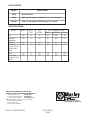
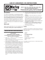
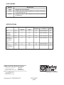
ACCESSORIES
MODEL DESCRIPTION
1011A One Hour Timer
1117A Wall cap with damper. Adaptable for 3” or 4” round duct.
AD1106 Roof Cap with damper. Will fit duct up to 7” round.
SPECIFICATIONS:
MODEL VOLTS DUCT CFM H.V.I. Certification (Sq. Ft.)
SIZE RATING BATH KITCHEN OTHER
761 120 4” 70 65 N/A 85
763/768IC 120 4” 90 85 N/A 115
8090/8090L
765/770IC 120 4” 110 105 N/A 135
7100/7100L 120 4” 100 95 N/A 125
7100H/7100FLH
7100FL/8100
8100L
7130 120 4” 130 120 N/A 165
7150/7150L 120 4” 150 140 N/A 190
7150H/7150FLH,
7150FL
Part No. 5200-2500-003 ECR 35922
10/03
470 Beauty Spot Rd. East
Bennettsville, SC 29512 USA
HOW TO OBTAIN WARRANTY SERVICE AND
WARRANTY PARTS PLUS GENERAL INFORMATION
1. Warranty Service or Parts 1-800-642-4328
2. Purchase Replacement Parts 1-800-654-3545
3. General Product Information www.marleymep.com
Note: When obtaining service always have the following:
1. Model number of the product
2. Date of manufacture
3. Part number or description
Page is loading ...

TORNILLOS DE MONTAJE
DEL SOPLADOR
ALETAS DE MONTAJE
DE LA REJILLA
SOPORTE DE
MONTAJE DE LA
REJILLA
SALIDA DE DESCARGA
DE AIRE
SALIDA DE
DESCARGA
DE AIRE
SOPORTES
DE MONTAJE
SOPORTES
DE MONTAJE
CUBIERTA DE
LA CAJA DE
SALIDA
CUBIERTA DE
LA CAJA DE
SALIDA
TORNILLOS DE MONTAJE
DEL SOPLADOR
UNIDAD
SOPLADORA
UNIDAD SOPLADORA
CONJUNTO DEL
REFLECTOR
PIEZA ELASTICA
DE LA REJILLA
REJILLA
REJILLA
LENTE
292 MM (11
1
⁄2)
318 MM (12
1
⁄
2)
292 MM (11
1
⁄2)
318 MM (12
1
⁄2)
MODELOS:
761, 763 AND 765
FIG. 1
MODELOS:
768IC AND 770IC
FIG. 2
270 MM (10
5
⁄8)
191 mm (7
1
⁄2)
244 mm (9
5
⁄8)
TORNILLO DE
MONTAJE DEL
REFLECTOR
270 MM (10
5
⁄8)
124 mm
(4
7
⁄8)
244 MM (9
5
⁄8
)
Page is loading ...

FIG. 6
FIG. 7
¡ATENCION!
ASEGURESE DE QUE TODO EL CONEXIONADO CUMPLA CON LAS REGLAMENTA-
CIONES ELECTRICAS LOCALES Y NACIONALES,
Y QUE EL BASTIDOR ESTE PUESTO A TIERRA ADECUADAMENTE.
CASQUETE DE TECHO
CASQUETE
DE PARED
CONDUCTO REDONDO
DE 10 CM (4”) DE
DIAMETRO
CONDUCTO REDONDO
DE 10 CM (4”) DE
DIAMETRO
TECHO
CAJA DE SALIDA
CONECTOR HEMBRA
DIAGRAMA DE CONEXIONADO
MODELOS 768IC, 770IC
LUZ
VERDE
BLANCO
BLANCO
BLANCO
VERDE
NEGRO
DIAGRAMA DE CONEXIONADO
MODELOS 7100H, 7150H
SENSOR
TEMPORIZADOR
SENSOR
NEGRO
BLANCO
BLANCO
BLANCO
DIAGRAMA DE CONEXIONADO
MODELOS 7100L, 7150L,
7100FL, 7150FL, 8090L Y 8100L
LUZ
LUZ NOCTURNA
BLUE
BROWN
BLANCO
BLANCO
BLANCO
BLANCO
NEGRO
DIAGRAMA DE CONEXIONADO
MODELOS 7100FLH, 7150FLH
LUZ
BALASTO
BALASTO
LUZ
LUZ NOCTURNA
BLU
BLU
MARRON
VENTILADOR
NEGRO
BLANCO
TORNILLO DE PUESTA A TIERRA
TIERRA
BLANCO
NEGRO
NEGRO
DIAGRAMA DE CONEXIONADO
MODELOS 761, 763, 765
7100, 7130, 7150, 8090
Y 8100
INTERR.
DE PARED
INTERR.
DE PARED
INTERR.
DE PARED
INTERR.
DE PARED
INTERR.
DE PARED
INTERR.
DE PARED
ALIMENTACION
ELECTRICA,
120 VOLT CA, 60 Hz
CAJA DE SALIDA
RECEPTACLE
VENTILADOR
TORNILLO DE PUESTA A TIERRA
TIERRA
BLANCO
NEGRO
NEGRO
NEGRO
ALIMENTACION ELEC-
TRICA,
120 VOLT CA, 60 Hz
CAJA DE SALIDA
RECEPTACLE
VENTILADOR
TORNILLO DE PUESTA A TIERRA
TIERRA
BLANCO
NEGRO
NEGRO
NEGRO
NEGRO
ALIMENTACION ELEC-
TRICA,
120 VOLT CA, 60 Hz
INTERR.
DE PARED
INTERR.
DE PARED
INTERR.
DE PARED
INTERR.
DE PARED
CAJA DE SALIDA
VENTILADOR
TEMPORIZADOR
TORNILLO DE PUESTA A TIERRA
TIERRA
BLANCO
NEGRO
NEGRO
ALIMENTACION
ELECTRICA,
120 VOLT CA, 60 Hz
CAJA DE SALIDA
CONECTOR HEMBRA
VENTILADOR
TORNILLO DE PUESTA A TIERRA
TIERRA
BLANCO
NEGRO
NEGRO
NEGRO
NEGRO
ALIMENTACION
ELECTRICA,
120 VOLT CA, 60 Hz
NEGRO
BLANCO
NEGRO
BLANCO
Page is loading ...

SALIDA DE DESCARGA
DE AIRE
CUBIERTA
DE LA CAJA DE
SALIDA
ALETAS DE MONTAJE
DE LA REJILLA
UNIDAD
SOPLADORA
REJILLA
318 MM (12 1/2”)
284 MM
(11 3/16”)
194 MM (7 5/8”)
254 MM (10”)
292 MM (11 1/2”)
PIEZA ELASTICA
DE LA REJILLA
TORNILLOS DE
MONTAJE DEL
SOPLADOR
CONECTORES
DE CABLE
SENSOR DE
HUMEDAD
MODELOS:
7100, 7130, 7150,
7100H, 7150H,
8090 Y 8100
CUBIERTA
DE LA CAJA DE
SALIDA
ALETAS DE MONTAJE DE
LA REJILLA
UNIDAD
SOPLADORA
REJILLA
318 MM (12 1/2”)
318 MM (12 1/2”)
284 MM
(11 3/16”)
194 MM (7 5/8”)
254 MM (10”)
PIEZA ELASTICA
DE LA REJILLA
TORNILLOS DE MONTA-
JE DEL SOPLADOR
TORNILLO DE
MONTAJE DEL
REFLECTOR
CONJUNTO DEL
REFLECTOR
MODELOS:
7100L, 7150L, 7100FLH,
7150FLH, 7100FL, 7150FL,
8090L Y 8100L
FIG. 8
FIG. 9
SOPORTES DE
MONTAJE
SOPORTES
DE MONTAJE
CONECTOR DE
CABLE
(MACHO)
CONECTOR
DE CABLE
(MACHO)
TEMPORIZADOR
TEMPORIZADOR
SENSOR DE
HUMEDAD
SALIDA DE DESCARGA
DE AIRE
CONECTORES
DE CABLE
Page is loading ...

ACCESORIOS
MODELO DESCRIPCION
1011A Temporizador de una hora
1117A Casquete para pared, con compuerta reguladora. Adaptable para
conductos redondos de 7,5 cm (3”) o 10 cm (4”) de diámetro.
AD1106 Casquete para techo, con compuerta reguladora. Se adapta a con-
ductos redondos de hasta 18 cm (7”).
ESPECIFICACIONES:
MODELO TENSION CERTIFICACIÓN H. V. I. (PIES CUADRADOS)
(VOLT) BAÑO COCINA OTROS
761 120 4” 70 65 N/A 85
763/768IC 120 4” 90 85 N/A 115
8090/8090L
765/770IC 120 4” 110 105 N/A 135
7100/7100L 120 4” 100 95 N/A 125
7100H/7100FLH
7100FL/8100
8100L
7130 120 4” 130 120 N/A 165
7150/7150L 120 4” 150 140 N/A 190
7150H/7150FLH,
7150FL
Número de parte 5200-2500-003 ECR 35922
10/03
470 Beauty Spot Rd. East
Bennettsville, SC 29512
Estados Unidos de América
DIAMETRO DEL
CONDUCTO
(PULGADAS)
CAUDAL
(PIES CUBICOS
POR MINUTO)
NOTAS:
1. H.V.I.: INSTITUTO DE VENTILACION DEL HOGAR (E. U. DE A.)
2. N/A: NO APLICABLE
COMO OBTENER SERVICIO Y PIEZAS BAJO GARANTIA MAS
INFORMACION GENERAL
1. Servicio o piezas bajo garantía 1-800-642-4328
2. Compra de piezas de repuesto 1-800-654-3545
3. Información general del producto www.marleymep.com
Nota: Cuando se solicite servicio tener siempre a mano lo siguiente:
1. Número de modelo del producto
2. Fecha de fabricación
3. Número de pieza o descripción
Page is loading ...
Page is loading ...
Page is loading ...

SCHÉMA 6
SCHÉMA 7
ATTENTION !
VÉRIFIEZ BIEN QUE TOUT LE CÂBLAGE EST EN CONFORMITÉ AVEC LES NORMES
ÉLECTRIQUES LOCALES ET NATIONALES ET QUE LE CHÂSSIS EST MIS À LA TERRE.
CHAPEAU DE TOIT
CHAPEAU
DE MUR
CONDUITE
CYLINDRIQUE
Ø 10 CM
CONDUITE
CYLINDRIQUE
Ø 10 CM
TOIT
BOÎTIER ÉLECTRIQUE
PRISE
SCHÉMA DE CÂBLAGE
MODÈLES 768IC, 770IC
ÉCLAIRAGE
VERT
BLANC
BLANC
BLANC
VERT
NOIR
SCHÉMA DE CÂBLAGE
MODÈLES 7100H, 7150H
DETECTEUR
DETECTEUR
MINUTERIE
NOIR
BLANC
BLANC
BLANC
SCHÉMA DE CÂBLAGE
MODÈLES 7100L, 7150L,
7100FL, 7150FL, 8090L ET
8100L
ÉCLAIRAGE
ECLAIRAGE NOCTURNA
BLEU
MARRON
BLANC
BLANC
BLANC
BLANC
NOIR
SCHÉMA DE CÂBLAGE
MODÈLES 7100FLH, 7150FLH
ÉCLAIRAGE
BALLAST
BALLAST
ÉCLAIRAGE
ECLAIRAGE NOCTURNA
BLEU
BLEU
MARRON
VENTILATEUR
NOIR
BLANC
VIS DE TERRE
TERRE
BLANC
NOIR
NOIR
SCHÉMA DE CÂBLAGE
MODÈLES 761, 763, 765
7100, 7130, 7150, 8090
ET 8100
INTERR.
MURAL
INTERR.
MURAL
INTERR.
MURAL
INTERR.
MURAL
INTERR.
MURAL
INTERR.
MURAL
SECTEUR
120 V CA 60 HZ
BOÎTIER ÉLECTRIQUE
PRISE
VENTILATEUR
VIS DE TERRE
TERRE
BLANC
NOIR
NOIR
NOIR
SECTEUR
120 V CA 60 HZ
BOÎTIER ÉLECTRIQUE
PRISE
VENTILATEUR
VIS DE TERRE
TERRE
BLANC
NOIR
NOIR
NOIR
NOIR
SECTEUR
120 V CA 60 HZ
INTERR.
MURAL
INTERR.
MURAL
INTERR.
MURAL
INTERR.
MURAL
BOÎTIER ÉLECTRIQUE
VENTILATEUR
MINUTERIE
VIS DE TERRE
TERRE
BLANC
NOIR
NOIR
SECTEUR
120 V CA 60 HZ
BOÎTIER ÉLECTRIQUE
PRISE
VENTILATEUR
VIS DE TERRE
TERRE
BLANC
NOIR
NOIR
NOIR
NOIR
SECTEUR
120 V CA 60 HZ
NOIR
BLANC
NOIR
BLANC
Page is loading ...
Page is loading ...
Page is loading ...
Page is loading ...
-
 1
1
-
 2
2
-
 3
3
-
 4
4
-
 5
5
-
 6
6
-
 7
7
-
 8
8
-
 9
9
-
 10
10
-
 11
11
-
 12
12
-
 13
13
-
 14
14
-
 15
15
-
 16
16
-
 17
17
-
 18
18
-
 19
19
-
 20
20
-
 21
21
-
 22
22
-
 23
23
-
 24
24


Marley Engineered Products 761 User manual
- Category
- Household fans
- Type
- User manual
Ask a question and I''ll find the answer in the document
Finding information in a document is now easier with AI
in other languages
Related papers
-
Marley Engineered Products FRR10512B User manual
-
-
-
-
-
-
-
-
-
Other documents
-
NuTone 605RP Installation guide
-
-
Silhouette SR001 The Renoir Installation guide
-
 Prime-Line B 654 Operating instructions
-
TowSmart 1461 Installation guide
-
-
Poly Planar PM2 Installation guide
-
 Prime-Line R 7130 Operating instructions
-
OUKANING HG-HCXLST-2808 Operating instructions
-
Broan AE50110DCS Installation guide

