Page is loading ...

Pololu Maestro Servo
Controller User’s Guide
Pololu Maestro Servo Controller User’s Guide © 2001–2022 Pololu Corporation
https://www.pololu.com/docs/0J40/all Page 1 of 102

1. Overview . . . . . . . . . . . . . . . . . . . . . . . . . . . . . . . . . . . . . . . . . . . . . . 4
1.a. Micro Maestro Pinout and Components . . . . . . . . . . . . . . . . . . . . . . . . . . 10
1.b. Mini Maestro Pinout and Components . . . . . . . . . . . . . . . . . . . . . . . . . . 13
1.c. Indicator LEDs . . . . . . . . . . . . . . . . . . . . . . . . . . . . . . . . . . . . . . . 18
1.d. Supported Operating Systems . . . . . . . . . . . . . . . . . . . . . . . . . . . . . . 19
2. Contacting Pololu . . . . . . . . . . . . . . . . . . . . . . . . . . . . . . . . . . . . . . . . . 20
3. Getting Started . . . . . . . . . . . . . . . . . . . . . . . . . . . . . . . . . . . . . . . . . . 21
3.a. Installing Windows Drivers and Software . . . . . . . . . . . . . . . . . . . . . . . . . 21
3.b. Installing Linux Drivers and Software . . . . . . . . . . . . . . . . . . . . . . . . . . . 26
3.c. Using the Maestro without USB . . . . . . . . . . . . . . . . . . . . . . . . . . . . . . 27
4. Using the Maestro Control Center . . . . . . . . . . . . . . . . . . . . . . . . . . . . . . . . 29
4.a. Status and Real-time Control . . . . . . . . . . . . . . . . . . . . . . . . . . . . . . . 29
4.b. Channel Settings . . . . . . . . . . . . . . . . . . . . . . . . . . . . . . . . . . . . . 31
4.c. Sequencer . . . . . . . . . . . . . . . . . . . . . . . . . . . . . . . . . . . . . . . . . 34
4.d. Entering a Script . . . . . . . . . . . . . . . . . . . . . . . . . . . . . . . . . . . . . . 37
4.e. Errors . . . . . . . . . . . . . . . . . . . . . . . . . . . . . . . . . . . . . . . . . . . 38
4.f. Upgrading Firmware . . . . . . . . . . . . . . . . . . . . . . . . . . . . . . . . . . . . 41
4.f.1. Hard Bootloader Reset . . . . . . . . . . . . . . . . . . . . . . . . . . . . . . 43
5. Serial Interface . . . . . . . . . . . . . . . . . . . . . . . . . . . . . . . . . . . . . . . . . . 46
5.a. Serial Settings . . . . . . . . . . . . . . . . . . . . . . . . . . . . . . . . . . . . . . . 46
5.b. TTL Serial . . . . . . . . . . . . . . . . . . . . . . . . . . . . . . . . . . . . . . . . . 49
5.c. Command Protocols . . . . . . . . . . . . . . . . . . . . . . . . . . . . . . . . . . . . 50
5.d. Cyclic Redundancy Check (CRC) Error Detection . . . . . . . . . . . . . . . . . . . . 52
5.e. Serial Servo Commands . . . . . . . . . . . . . . . . . . . . . . . . . . . . . . . . . . 54
5.f. Serial Script Commands . . . . . . . . . . . . . . . . . . . . . . . . . . . . . . . . . . 59
5.g. Daisy Chaining . . . . . . . . . . . . . . . . . . . . . . . . . . . . . . . . . . . . . . 60
5.h. Serial Example Code . . . . . . . . . . . . . . . . . . . . . . . . . . . . . . . . . . . 62
5.h.1. Cross-platform C . . . . . . . . . . . . . . . . . . . . . . . . . . . . . . . . . 62
5.h.2. Windows C . . . . . . . . . . . . . . . . . . . . . . . . . . . . . . . . . . . . 65
5.h.3. PIC18F4550 . . . . . . . . . . . . . . . . . . . . . . . . . . . . . . . . . . . 65
5.h.4. Bash script . . . . . . . . . . . . . . . . . . . . . . . . . . . . . . . . . . . . 66
5.h.5. Arduino library . . . . . . . . . . . . . . . . . . . . . . . . . . . . . . . . . . 67
6. The Maestro Scripting Language . . . . . . . . . . . . . . . . . . . . . . . . . . . . . . . . . 69
6.a. Maestro Script Language Basics . . . . . . . . . . . . . . . . . . . . . . . . . . . . . 69
6.b. Command Reference . . . . . . . . . . . . . . . . . . . . . . . . . . . . . . . . . . . 72
6.c. Example Scripts . . . . . . . . . . . . . . . . . . . . . . . . . . . . . . . . . . . . . . 77
6.d. Script Specifications . . . . . . . . . . . . . . . . . . . . . . . . . . . . . . . . . . . . 89
7. Wiring Examples . . . . . . . . . . . . . . . . . . . . . . . . . . . . . . . . . . . . . . . . . 90
Pololu Maestro Servo Controller User’s Guide © 2001–2022 Pololu Corporation
Page 2 of 102

7.a. Powering the Maestro . . . . . . . . . . . . . . . . . . . . . . . . . . . . . . . . . . . 90
7.b. Attaching Servos and Peripherals . . . . . . . . . . . . . . . . . . . . . . . . . . . . . 91
7.c. Connecting to a Microcontroller . . . . . . . . . . . . . . . . . . . . . . . . . . . . . . 94
8. Writing PC Software to Control the Maestro . . . . . . . . . . . . . . . . . . . . . . . . . . . 96
9. Maestro Settings Limitations . . . . . . . . . . . . . . . . . . . . . . . . . . . . . . . . . . . 98
10. Related Resources . . . . . . . . . . . . . . . . . . . . . . . . . . . . . . . . . . . . . . 101
Pololu Maestro Servo Controller User’s Guide © 2001–2022 Pololu Corporation
Page 3 of 102

1. Overview
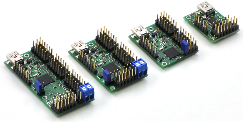
The Maestros are Pololu’s second-generation
family of USB servo controllers. The Maestro
family consists of four controllers, each available
fully assembled or as a partial kit:
•Micro Maestro 6 [https://www.pololu.com/
product/1350]
•Mini Maestro 12 [https://www.pololu.com/
product/1352]
•Mini Maestro 18 [https://www.pololu.com/
product/1354]
•Mini Maestro 24 [https://www.pololu.com/
product/1356]
With three control methods — USB for direct connection to a PC computer, TTL serial for use
with embedded systems, and internal scripting for self-contained, host controller-free applications
— and channels that can be configured as servo outputs for use with radio control (RC) servos
[https://www.pololu.com/category/23/rc-servos] or electronic speed controls (ESCs), digital outputs, or
analog/digital inputs, the Maestro is a highly versatile servo controller and general I/O board in a
highly compact package. The extremely precise, high-resolution servo pulses have a jitter of less
than 200 ns, making the Maestro well suited for high-performance animatronics, and built-in speed
and acceleration control make it easy to achieve smooth, seamless movements without requiring the
control source to constantly compute and stream intermediate position updates to the Maestro. The
Maestro features configurable pulse rates (up to 333 Hz for Mini Maestros) and can generate a wide
range of pulses to allow maximum responsiveness and range from modern servos. Units can be daisy-
chained with additional Pololu servo and motor controllers on a single serial line.
Pololu Maestro Servo Controller User’s Guide © 2001–2022 Pololu Corporation
1. Overview Page 4 of 102

A free configuration and control program is available for Windows and Linux (see Section 4), making
it simple to configure and test the board over USB, create sequences of servo movements for
animatronics or walking robots, and write, step through, and run scripts stored in the servo controller.
The Maestro’s internal script memory allows storage of servo positions that can be automatically
played back without any computer or external microcontroller connected (see Section 6).
The Maestros’ channels can also be used as general-purpose digital outputs and analog or digital
inputs, providing an easy way to read sensors and control peripherals directly from a PC over USB.
These inputs can be used with the scripting system to enable creation of self-contained animatronic
displays that respond to external stimuli.
AUSB A to mini-B cable [https://www.pololu.com/product/130] (not included) is required to connect this
device to a computer.
Pololu Maestro Servo Controller User’s Guide © 2001–2022 Pololu Corporation
1. Overview Page 5 of 102

Features
• Three control methods: USB, TTL (5 V) serial,
and internal scripting
• 0.25μs output pulse width resolution
(corresponds to approximately 0.025° for a
typical servo, which is beyond what the servo
could resolve)
• Configurable pulse rate and wide pulse range
(see the Maestro comparison table below)
• Individual speed and acceleration control for
each channel
• Channels can be optionally configured to go to
a specified position or turn off on startup or error
• Alternate channel functions allow the channels
to be used as:
◦ General-purpose digital outputs (0 or
5 V)
◦ Analog or digital inputs (channels 0 –
11 can be analog inputs; channels 12+
can be digital inputs)
◦ One channel can be a PWM output
with frequency from 2.93 kHz to
12 MHz and up to 10 bits of resolution
(see Section 4.a for details)
• A simple scripting language lets you program
the controller to perform complex actions even
after its USB and serial connections are
removed
Pololu Maestro Servo Controller User’s Guide © 2001–2022 Pololu Corporation
1. Overview Page 6 of 102

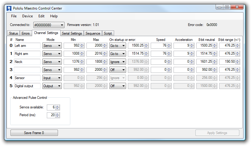
The Channel Settings tab in the Maestro
Control Center.
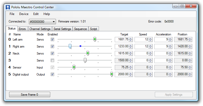
The Status tab in the Maestro Control
Center.
• Free configuration and control application for
Windows and Linux makes it easy to:
◦ Configure and test your controller
◦ Create, run, and save sequences of
servo movements for animatronics and
walking robots
◦ Write, step through, and run scripts
stored in the servo controller
• Two ways to write software to control the
Maestro from a PC:
◦ Virtual COM port makes it easy to
send serial commands from any
development environment that
supports serial communication
◦Pololu USB Software Development
Kit [https://www.pololu.com/docs/0J41]
allows use of more advanced native
USB commands and includes example
code in C#, Visual Basic .NET, and
Visual C++
• TTL serial features:
◦ Supports 300 – 200,000 bps in fixed-
baud mode, 300 – 115,200 bps in
autodetect-baud mode
◦ Simultaneously supports the Pololu
protocol, which gives access to
advanced functionality, and the simpler
Scott Edwards MiniSSC II protocol
(there is no need to configure the
device for a particular protocol mode)
◦ Can be daisy-chained with other
Pololu servo and motor controllers
using a single serial transmit line
◦ Chain input allows reception of data
from multiple Mini Maestros using a
Pololu Maestro Servo Controller User’s Guide © 2001–2022 Pololu Corporation
1. Overview Page 7 of 102

single serial receive line without extra components (does not apply to Micro
Maestros)
◦ Can function as a general-purpose USB-to-TTL serial adapter for projects controlled
from a PC
• Board can be powered off of USB or a 5 – 16 V battery, and it makes the regulated 5V
available to the user
• Upgradable firmware
Pololu Maestro Servo Controller User’s Guide © 2001–2022 Pololu Corporation
1. Overview Page 8 of 102

Maestro Comparison Table
Micro
Maestro
Mini
Maestro 12
Mini
Maestro 18
Mini
Maestro 24
Channels: 6 12 18 24
Analog input
channels: 6 12 12 12
Digital input
channels: 0 0 6 12
Width:
0.85"
(2.16 cm)
1.10"
(2.79 cm)
1.10"
(2.79 cm)
1.10"
(2.79 cm)
Length:
1.20"
(3.05 cm)
1.42"
(3.61 cm)
1.80"
(4.57 cm)
2.30"
(5.84 cm)
Weight(1):3.0 g 4.2 g 4.9 g 6.0 g
Configurable pulse
rate(2):
33–100 Hz 1–333 Hz 1–333 Hz 1–333 Hz
Pulse range(2):64–3280 μs 64–4080 μs 64–4080 μs 64–4080 μs
Script size(3):1 KB 8 KB 8 KB 8 KB
1This is the weight of the board without header pins or terminal blocks.
2The available pulse rate and range depend on each other and factors such as baud rate and number of
channels used. See Section 9 for details.
3The user script system is more powerful on the Mini Maestro than on the Micro Maestro. See Section 6.d for
details.
Pololu Maestro Servo Controller User’s Guide © 2001–2022 Pololu Corporation
1. Overview Page 9 of 102

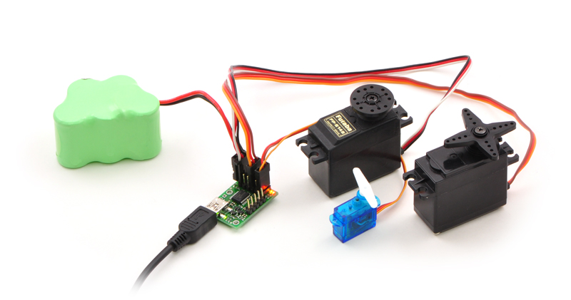
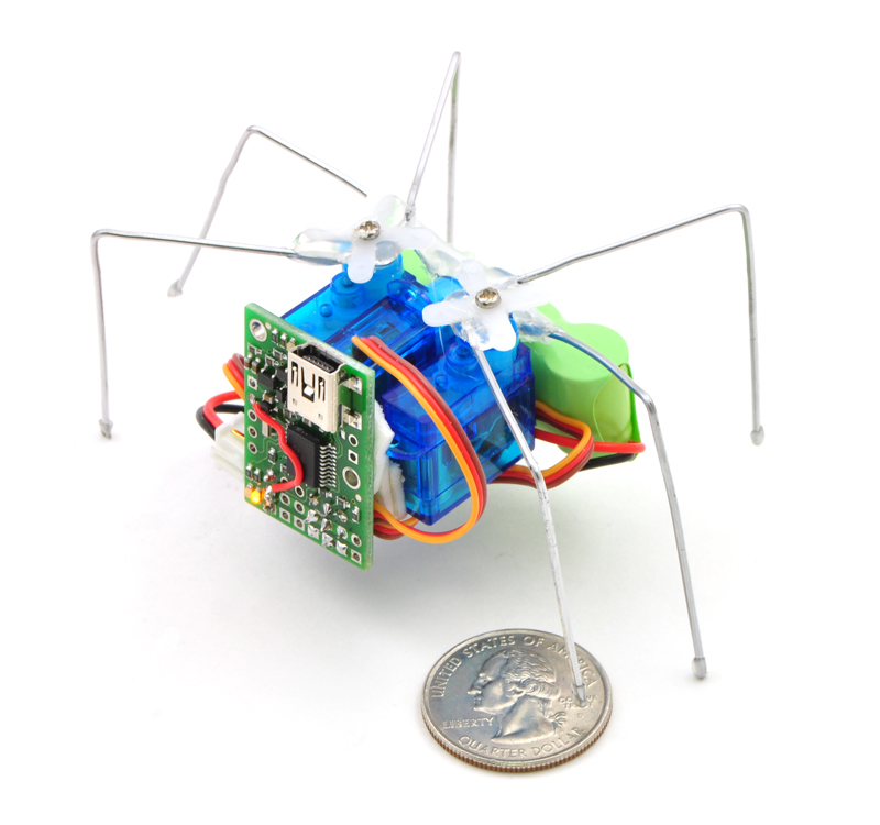
Micro Maestro as the brains of a tiny
hexapod robot.
Application Examples
• Serial servo controller for multi-servo projects
(e.g. robot arms, animatronics, fun-house
displays) based on microcontroller boards such
as the BASIC Stamp, Orangutan robot
controllers [https://www.pololu.com/category/8/
robot-controllers], or Arduino platforms
• Computer-based servo control over USB port
• Computer interface for sensors and other
electronics:
◦ Read a gyro or accelerometer
[https://www.pololu.com/category/80/
accelerometers-gyros-compasses] from a
computer for novel user interfaces
◦ Control a string of ShiftBrites
[https://www.pololu.com/product/1222] from
a computer for mood lighting
• General I/O expansion for microcontroller
projects
• Programmable, self-contained Halloween or
Christmas display controller that responds to
sensors
• Self-contained servo tester
1.a. Micro Maestro Pinout and Components
Pololu Maestro Servo Controller User’s Guide © 2001–2022 Pololu Corporation
1. Overview Page 10 of 102

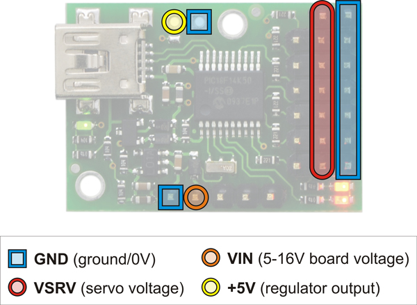
Micro Maestro power pins.
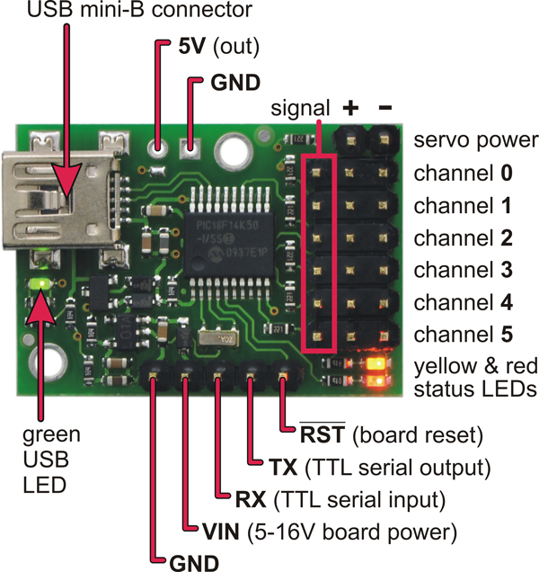
Micro Maestro 6-channel USB servo controller
(fully assembled) labeled top view.
Note: This section applies to the Micro Maestro servo controller. Please see Section
1.b for Mini Maestro pinout and component information.
The Pololu Micro Maestro 6-channel servo controller can connect to a computer’s USB port via a
USB A to mini-B cable [https://www.pololu.com/product/130] (not included). The USB connection is used
to configure the servo controller. It can also be used to send commands to the servo controller, get
information about the servo controller’s current state, and send and receive TTL serial bytes on the
TX and RX lines.
The processor and the servos can have separate power
supplies.
Processor power must come either from USB or from
an external 5–16V power supply connected to the VIN
and GND inputs. It is safe to have an external power
supply connected at the same time that USB is
connected; in such cases the processor will be powered
from the external supply. Note that if the external supply
falls below 5 V, correct operation is not guaranteed, even
if USB is also connected.
Pololu Maestro Servo Controller User’s Guide © 2001–2022 Pololu Corporation
1. Overview Page 11 of 102

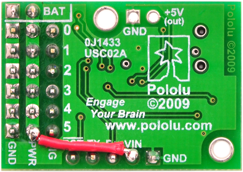
Micro Maestro configured to use
a single power supply for both
board and servos.
Servo power connections are provided in the upper right corner of the Micro Maestro board. Servo
power is passed directly to the servos without going through a regulator, so the only restrictions on
your servo power supply are that it must be within the operating range of your servos and provide
enough current for your application. Please consult the datasheets for your servos to determine an
appropriate servo power source, and note that a ballpark figure for the current draw of an average
straining servo is 1 A.
You can power the Maestro’s processor and servos from a single
power supply by connecting the positive power line to both VIN
and the servo power ports. An easy way to accomplish this on the
Micro Maestro is to solder a wire on the bottom of the board
between VIN and one of the servo power connections as shown
in the picture to the right. Only one ground connection is needed
because all ground pins on the board are connected.
The 5V (out) power output allows you to power your own 5V
devices from the on-board 50mA regulator or directly from USB.
The on-board regulator is used whenever VIN is powered; in this
case, since the Maestro requires 30 mA, there is about 20 mA
available to power other devices.
The SIG lines (0,1,2, …) are used for sending pulses to servos, controlling digital outputs, and
measuring analog voltages. These lines are protected by 220Ω resistors. The total current limit (in or
out) for these pins is 60 mA, but when using the on-board regulator the current out is limited to 20 mA
(see above.)
The RX line is used to receive non-inverted TTL (0–5 V) serial bytes, such as those from
microcontroller UARTs. These bytes can either be serial commands for the Maestro, arbitrary bytes to
send back to the computer via the USB connection, or both. For more information about the Maestro’s
serial interface, see Section 5.a. Note that the Maestro will probably be able to receive 3.3V TTL serial
bytes, but it is not guaranteed to read 3.3V as high on the RX pin, so you should boost 3.3V TTL serial
signals to above 4V if you want to ensure reliable operation.
The TX line transmits non-inverted TTL (0–5 V) serial bytes. These bytes can either be responses
to serial commands sent to the Maestro, or arbitrary bytes sent from the computer via the USB
connection.
The RST pin can be driven low to reset the Maestro’s microcontroller, but this should not be necessary
for typical applications. The line is internally pulled high, so it is safe to leave this pin unconnected.
Driving RST low is roughly equivalent to powering off the Maestro; it will not reset any of the
configuration parameters stored in non-volatile memory. To reset the configuration parameters, select
Pololu Maestro Servo Controller User’s Guide © 2001–2022 Pololu Corporation
1. Overview Page 12 of 102

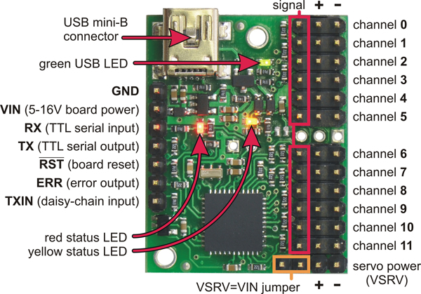
Mini Maestro 12-channel USB servo controller (fully
assembled) labeled top view.
Device > Reset to default settings… in the Maestro Control Center.
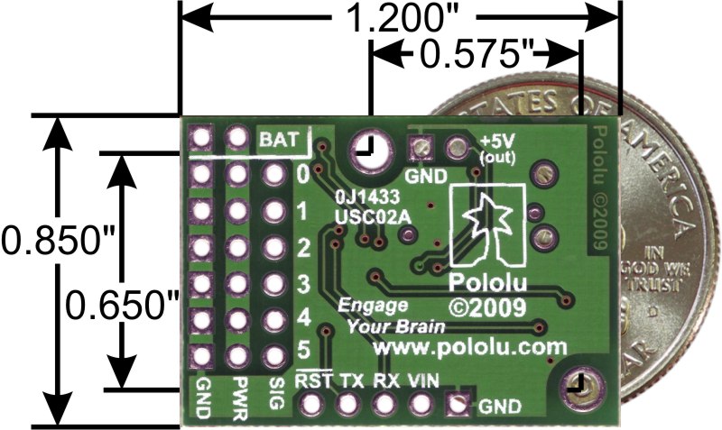
Micro Maestro 6-channel USB servo controller
bottom view with quarter for size reference.
The dimensions of the Micro Maestro PCB are 1.2″ × 0.85″. The mounting holes have a diameter of
0.086″and are intended for #2 or M2 screws. The vertical and horizontal distances between the two
mounting holes are 0.65″ and 0.575″. The Micro Maestro weighs 3.0 g (0.11 oz) without header pins.
1.b. Mini Maestro Pinout and Components
Pololu Maestro Servo Controller User’s Guide © 2001–2022 Pololu Corporation
1. Overview Page 13 of 102


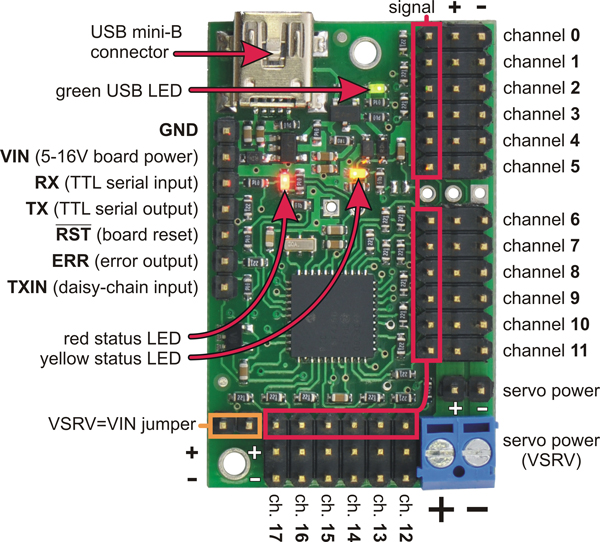
Mini Maestro 24-channel USB servo controller (fully
assembled) labeled top view.
Note: This section applies to the Mini Maestro 12, 18, and 24 servo controllers. Please
see Section 1.a for Micro Maestro pinout and component information.
The Pololu Mini Maestro 12-,18-, and 24-channel servo controllers can connect to a computer’s
USB port via a USB A to mini-B cable [https://www.pololu.com/product/130] (not included). The USB
connection is used to configure the servo controller. It can also be used to send commands to the
servo controller, get information about the servo controller’s current state, and send and receive TTL
serial bytes on the TX and RX lines.
Pololu Maestro Servo Controller User’s Guide © 2001–2022 Pololu Corporation
1. Overview Page 15 of 102

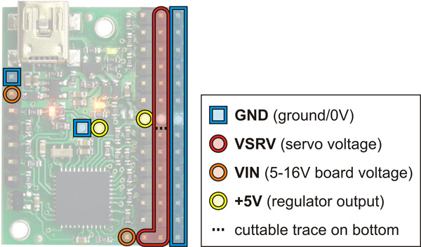
Mini Maestro 12 power pins.
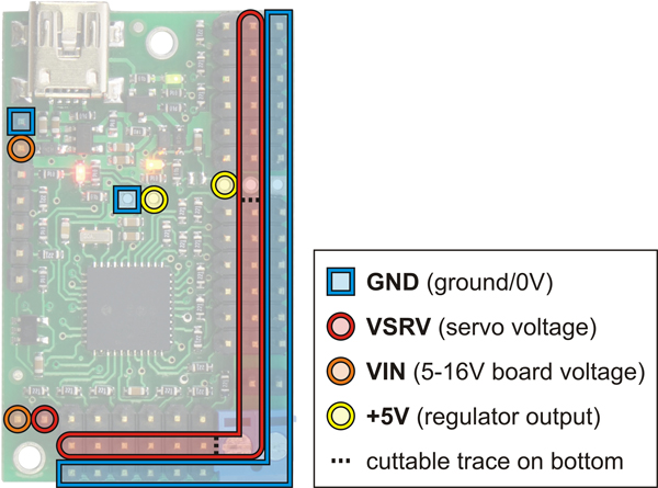
Mini Maestro 18 power pins.
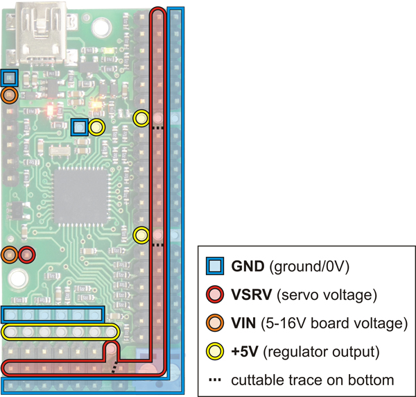
Mini Maestro 24 power pins.
The processor and the servos can have separate power
supplies.
Processor power must come either from USB or from
an external 5–16V power supply connected to the VIN
and GND inputs on the left side of the board. It is safe to
have an external power supply connected at the same
time that USB is connected; in that case the processor
will be powered from the external supply. Note that if the
external supply falls below 5 V, correct operation is not
guaranteed, even if USB is also connected.
Servo power connections are provided in the lower right
corner of the Mini Maestro board. On the Mini Maestro 18
and 24, you can make servo power connections via a
2-pin terminal block or a 2-pin 0.1″ header; the Mini
Maestro 12 only has a 2-pin 0.1″ header for connecting
servo power. Servo power is passed directly to the
servos without going through a regulator, so the only
restrictions on your servo power supply are that it must
be within the operating range of your servos and provide
enough current for your application. Please consult the
datasheets for your servos to determine an appropriate
servo power source, and note that a ballpark figure for
the current draw of an average straining servo is 1 A.
You can power the Maestro’s processor and servos from
a single power supply by connecting the positive power
line to both VIN and the servo power ports (only one
ground connection is needed because all ground pins on
the board are connected). The recommended way to do
this is to connect your power supply to the dedicated
servo power pins in the corner of the board and use the
included blue shorting block to connect the pins labeled
“VSRV=VIN”.
The 5V (out) power output allows you to power your own 5V devices from the 100mA on-board
regulator or directly from USB. The on-board regulator is used whenever VIN is powered; in this case,
since the Maestro requires 50 mA, there is about 50 mA available to power other devices.
Pololu Maestro Servo Controller User’s Guide © 2001–2022 Pololu Corporation
1. Overview Page 16 of 102

The signal lines (0,1,2, …) are used for sending pulses to servos, controlling digital outputs, and
measuring voltages. The total current limit (in or out) for these pins is 200 mA, but when using the
on-board regulator the current out is limited to 50 mA (see above.)
The RX line is used to receive non-inverted TTL (0–5 V) serial bytes, such as those from
microcontroller UARTs. These bytes can either be serial commands for the Maestro, arbitrary bytes to
send back to the computer via the USB connection, or both. For more information about the Maestro’s
serial interface, see Section 5.a. Note that the Maestro will probably be able to receive 3.3V TTL serial
bytes, but it is not guaranteed to read 3.3V as high on the RX pin, so you should boost 3.3V TTL serial
signals to above 4V if you want to ensure reliable operation.
The TX line transmits non-inverted TTL (0–5 V) serial bytes. These bytes are either generated by the
Mini Maestro itself (as responses to serial commands or arbitrary bytes sent from the computer via the
USB connection), or they come from the TXIN line.
The RST pin can be driven low to reset the Maestro’s microcontroller, but this should not be necessary
for typical applications. The line is internally pulled high, so it is safe to leave this pin unconnected.
Driving RST low is roughly equivalent to powering off the Maestro; it will not reset any of the
configuration parameters stored in non-volatile memory. To reset the configuration parameters, select
Device > Reset to default settings… in the Maestro Control Center.
The ERR line is an output that is tied to the red error/user LED. It is driven high when the red LED is
on, and it is a pulled low through the red LED when the red LED is off. The red LED turns on when
an error occurs, turns off when the error flags have been cleared, and can also be controlled by the
user script. Since the ERR line is never driven low, it is safe to connect the ERR line of multiple Mini
Maestros together. Please note, however, that doing this will cause the red LEDs of all connected Mini
Maestros to turn on whenever one of the Mini Maestros turns on its red LED. For more information on
the possible error conditions and response options, please see Section 4.e.
The TXIN line is a serial input line that makes it easy to chain together multiple Mini Maestros. Any
serial bytes received on this line will be buffered through an AND gate and transmitted on the TX line.
See Section 5.g for more information about daisy chaining.
Pololu Maestro Servo Controller User’s Guide © 2001–2022 Pololu Corporation
1. Overview Page 17 of 102

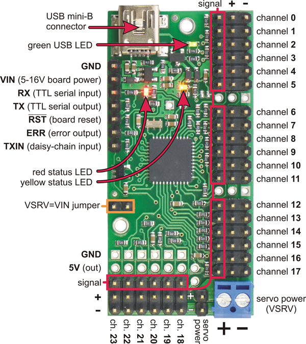
Bottom view with dimensions (in inches) of Pololu Micro and Mini Maestro
servo controllers.
The dimensions of the Mini Maestro PCBs are shown in the picture above, along with the Micro
Maestro for comparison. The mounting holes have a diameter of 0.086″and are intended for #2 or M2
screws. The vertical and horizontal distances between the two mounting holes are as follows: 1.2″ and
0.5″ for the Mini Maestro 12, 1.58″ and 0.5″ for the Mini Maestro 18, and 1.5″ and 0.5″ for the Mini
Maestro 24.
1.c. Indicator LEDs
The Maestro has three indicator LEDs:
• The green USB LED indicates the USB status of the device. When the Maestro is not
connected to a computer via the USB cable, the green LED will be off. When you connect
the Maestro to USB, the green LED will start blinking slowly. The blinking continues until the
Maestro receives a particular message from the computer indicating that the Maestro’s USB
drivers are installed correctly. After the Maestro gets this message, the green LED will be on,
but it will flicker briefly when there is USB activity. The control center application constantly
streams data from the Maestro, so when the control center is running and connected to the
Maestro, the green LED will flicker constantly.
• The red error/user LED usually indicates an error. The red LED turns on when an error
occurs, and turns off when the error flags have been cleared. See Section 4.e for more
information about errors. The red LED can also be controlled by the user script; the red LED
will be on if there is an error or if the script command for turning it on was run.
• The yellow status LED indicates the control status. When the Maestro is in auto-baud detect
mode (the default) and has not yet detected the baud rate, the yellow LED will blink slowly.
During this time the Maestro does not transmit any servo pulses. Once the Maestro is ready
to drive servos, the yellow LED will periodically flash briefly. The frequency of the flashes is
Pololu Maestro Servo Controller User’s Guide © 2001–2022 Pololu Corporation
1. Overview Page 18 of 102

proportional to the servo period (the amount of time between pulses on a single channel);
with a period of 20 ms the flashing occurs approximately once per second. The number of
flashes indicates the state: a single flash indicates that none of the servos are enabled (no
pulses are being sent) and all output channels are low, while a double flash indicates that
at least one of the servos is enabled or one of the output channels is being driven high.
Also, when a valid serial command is received, the yellow LED will emit a brief, dim flash
which ends when the next valid serial command is received or when the main blinking occurs
(whichever happens first). Mini Maestros with firmware version 1.00 only emit single flashes
unless a servo channel with a speed or acceleration limit is enabled. This behavior was fixed
in firmware version 1.02 to be consistent with the Micro Maestro.
When the Maestro is reset in some other way than being initially powered up, the red and/or yellow
LEDs blink four times to indicate the reset condition:
• Yellow off, red blinking: A brownout reset. This occurs when the Maestro’s 5 V line drops
below about 3.0 V, usually due to low batteries or an inadequate power supply.
• Yellow blinking, red off: The Maestro was reset by a low voltage on its RST line.
• Yellow and red blinking together: A firmware crash resulted in a “watchdog” reset. This also
occurs immediately following a firmware upgrade, as a normal part of the upgrade process.
• Yellow blinking, red steady: A firmware error resulted in a soft reset. This should never occur
during normal usage.
1.d. Supported Operating Systems
The Maestro USB drivers and configuration software work under Microsoft Windows XP, Windows
Vista, Windows 7, Windows 8, Windows 8.1, Windows 10, Windows 11, and Linux.
On ARM-based Linux machines such as the Raspberry Pi, the Maestro’s graphical configuration
program (the Maestro Control Center) does not work. This is caused by problems with Mono’s
implementations of WinForms on those systems.
We do not provide any software for macOS, but the Maestro’s two virtual serial ports are compatible
with macOS 10.7 (Lion) and later. The Maestro must be initially configured from a Windows or Linux
computer, but after that it can be controlled from a Mac. If you have macOS 10.11 or later, you will
need to update your Maestro’s firmware to version 1.03 or later to use the Maestro’s virtual serial ports
(see Section 4.f).
Pololu Maestro Servo Controller User’s Guide © 2001–2022 Pololu Corporation
1. Overview Page 19 of 102

2. Contacting Pololu
You can check the product page of your particular Maestro model for additional information. We would
be delighted to hear from you about any of your projects and about your experience with the Maestro.
You can contact us [https://www.pololu.com/contact] directly or post on our forum [http://forum.pololu.com/].
Tell us what we did well, what we could improve, what you would like to see in the future, or anything
else you would like to say!
Pololu Maestro Servo Controller User’s Guide © 2001–2022 Pololu Corporation
2. Contacting Pololu Page 20 of 102
/


