Page is loading ...

Notes:
If the magnet is not placed in front of the display to
select a tank shape, the tank selection sequence will
continue and the FULL light will flash 5 times. After the
FULL light flashes 5 times the tank shape selection
sequence will begin again. (Step 5) The tank shape
selection sequence will repeat 3 times. If no tank shape
selection is made in this time, the display will default to
a rectangular tank.
If the display was calibrated incorrectly, remove power
from the display and repeat the process. Recalibration
can not occur without cycling power.
FULL
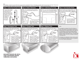
Step 3: Calibrating The Probe
With the 1/4, 1/2, 3/4 and FULL lights all flashing, fill
tank - if not yet full. For a level-by-level calibration,
do not fill tank and go to alt. instructions on page 2.
SL Series Level Monitor Calibration/Installation
Subject:
Revision:
For Installing and Calibrating SL 10-LED Level Monitors
08/16/04 D Revision Date: 04/10/06 Standards No.
Date Originated:
c 2006 Innovative Controls, Inc. All Rights Reserved
Note:
This calibration procedure must be performed to ensure that the indicated fluid levels on the display accurately match the actual levels in the tank. The tank can
be full or empty to begin calibration, but must be filled before beginning Step 4. To ensure proper calibration, do not have water in the fill tower.
Step 5: Rectangular Tank
When the 1/4 level lights begin to flash, place the
magnet back onto the master display before the
lights flash for the fifth time.
Remove the magnet.
Calibration for a rectangular
tank is now complete. If the
magnet is not placed in
time, wait until tank shape
sequence begins again.
Step 1: Install Tank Sender Unit
To ensure proper drainage,
it is highly recommended
that the sender unit is
mounted vertically on the
side of the tank by using a
90 degree 1/4" NPT fitting.
Connect sender unit to
the display and
the display to a
12 or 24 volt
power source.
Go to Step 2.
TANK
Step 2: Initiate Calibration
Within 1 min. of powering up the unit, place the
magnet over the master display between the 1/2
and 3/4 levels.
The 1/4,1/2, 3/4 and FULL
lights will flash in succession
and then they will flash
together - at the same time.
Step 4: Tank Selection Mode
Place the magnet over the display between 1/2 and
3/4 levels. The level lights will flash in sequence
upward beginning the tank selection mode.
You will now select the tank
shape. For a rectangular
tank, go to Step 5. For a T
tank, go to Step 6. For an
elliptical tank go to Step 7.
Step 6: T-Shaped Tank
When the 1/2 level lights begin to flash, place the
magnet back onto the master display before the
lights flash for the fifth time.
Remove the magnet.
Calibration for a T-shaped
tank is now complete. If the
magnet is not placed in
time, wait until tank shape
sequence begins again.
Step 7: Elliptical Tank
When the 3/4 level lights begin to flash, place the
magnet back onto the master display before the
lights flash for the fifth time.
Remove the magnet.
Calibration for an elliptical
tank is now complete. If the
magnet is not placed in
time, wait until tank shape
sequence begins again.
Page 1 of 3

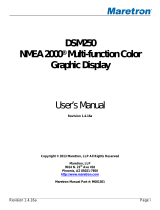
SL Series Level Monitor Calibration (Alternative)
Subject:
Revision:
For Manually Calibrating SL 10-LED Level Monitor to Unique Tank Styles and Capacities
08/16/04 D Revision Date: 04/10/06 Standards No.
Date Originated:
c 2004 Innovative Controls, Inc. All Rights Reserved
Alt. Step 5
Wait until the FULL level is flashing and place the
magnet over the display.
The 1/4 and EMPTY lights will
alternate flashing.
Alt. Step 4
With the tank empty and the 1/4, 1/2, 3/4 and FULL
lights flashing, place the magnet over the master
display between the 1/2 and 3/4 levels.
The 1/4,1/2,3/4, and FULL
lights will flash in succession,
bottom-up.
Alt. Step 6
Fill the tank to the desired 25% level. Check level
visually or by measuring depth.
25%
Note:
If none of the 3 calibration modes described on the previous page is acceptable, use this special calibration mode to set each of the water or foam levels
independently. Perform Steps 1, 2, and 3 on previous page before astarting Alt. Step 4.
Alt. Step 7
Place the magnet over the display. The 1/4 lights will
stay on while the 1/2 lights begin to flash.
Alt. Step 13
Place the magnet over the display to complete the
alternate calibration process.
Alt. Step 9
Place the magnet over the display. The 1/4 and 1/2
lights will be on while the 3/4 lights begin to flash.
Alt. Step 11
Place the magnet over the display. The 1/4, 1/2 and
3/4 lights will be on while the FULL lights begin
to flash.
Alt. Step 8
Fill the tank to the desired 50% level. Check level
visually or by measuring depth.
50%
Alt. Step 10
Fill the tank to the desired 50% level. Check level
visually or by measuring depth.
75%
Alt. Step 12
Fill the tank to the desired FULL level.
100%
Notes:
Dual level monitors must be calibrated one
side (tank) at a time for both standard
calibration (front of page) and alternate
calibration (above).
Both calibration methods will work for
all styles of SL level monitor master
displays (10 and 14 LED water and foam,
mini masters, and dual displays)
1/2
F
3/4
1/4
E
Page 2 of 3

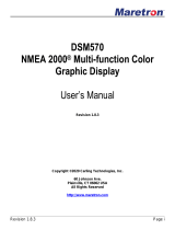
SL Series Level Monitor Display Installation
Subject:
Revision:
For Installing Single and Dual SL 10-LED Tank Level Monitor Displays
10/5/04 04/10/06D Revision Date: Standards No.
Date Originated:
c 2004 Innovative Controls, Inc. All Rights Reserved
Step 1: Layout Panel Cut-Outs
Using the dimensions below (can also be used as
templates), layout the location(s) for the display(s).
Allow enough clearance between displays and
other components. Note overall display dimensions.
2.9 5.3
5.5
Step 2: Install Display
Feed cables through panel cut-out and secure
display using the hardware provided. (Qty.4 1/2"
long 8-32 flathead SCS, and nylon insert locking
nuts)Weld nuts or press-in nuts are also acceptable
for panel-mounting.
TANK
Step 3: Connect Display
Connect the display to the sender
unit and a12 or 24 volt power
source.
1/2
F
3/4
1/4
E
1.88" [48mm]
2.38" [61mm] 4.75" [121mm]
4.25" [108mm]
Single Tank
Level Monitor
Display Cut-out
Dual Tank
Level Monitor
Display Cut-out
0.188" [5mm] DIA.
4.88"
[124mm]
4.50"
[115mm]
Page 3 of 3

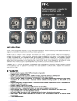
SL Series Tank Sender Installation Instructions
Subject:
Revision:
For Installing SL Series Tank Level Sender Unit
12/05/06 B Revision Date: 12/16/06 Standards No.
Date Originated:
c 2006 Innovative Controls, Inc. All Rights Reserved
The SL Level Monitor is a pressure transducer system that converts pressure (psi) into voltage. The 5.0 VDC sensor
outputs 0.25-0.31 VDC at no pressure up to a max of 4.5 VDC at 69” of water.
Page 1 of 1
TANK
Step 2: Install Sender
Screw the sender
unit into 1/4” NPT
street elbow using
teflon tape. Be
careful to not
allow the tape
into the sensor
bore. This will
affect operation.
Do not insert
anything into the
sensor bore. The
internal diaphragm
may be damaged.
Step 3: Check Sender Seal
This step is optional.
You may choose to test the
seal of the sensor by
partially filling the tank and
inspecting the fittings for
leaks.
Master
Display
To 12 Volt
Supply
Step 4: Connect Sender Unit
Connect the sender unit
to the master display via an
extension cable.
See SL Calibration Instructions
to calibrate sender unit.
Step 1: Install Fitting in Tank
Install an elbow of your
choice into side of the
tank that will accept
the 1/4” NPT thread
of the sender unit as
shown. The elbow
should be installed at
a height that will place
the diaphram inside
the sender at
between 1.5“ and
2” from the bottom of
the tank.
TANK
1.5”- 2.0”
TANK
TANK
/