Page is loading ...

63296 Powell Butte Hwy • Bend, OR 97701 • (541) 318-6060 • iFlyEi.com
MVP-50T
Installation Instructions
II 1211061 - Rev. F: 02/21/18***
The MVP-50T is an STC’d & TSO’d Primary Replacement
for Engine and Aircraft System Instruments
Read this manual before installing this
instrument. It contains information that
may aect your decision to install this
product and/or the safety of your aircraft.
Model # :
Serial # :

Blank Page
22

Important Notice
***** MUST READ *****
Page 1 of 4
If you think it is not important to read this manual, you're wrong! This manual contains important
operating information that may affect the safety of the pilot, passengers, aircraft, operation of the system or
time to install the system. You MUST read the manual prior to installing this system. Any deviation from these
installation instructions is the sole responsibility of the installer and should be done in accordance with AC
43.13.
Read the Warranty/Agreement. There is information in the Warranty/Agreement that may alter your decision
to install this product. If you do not accept the terms of the Warranty/Agreement, do not install this
product. This product may be returned for a refund. Contact Electronics International Inc. for details.
If you are not an FAA Certified Aircraft Mechanic familiar with the issues of installing aircraft N1,
N2, ITT, Torque, Volt, Amp, Oil Temperature and Pressure instruments, Do Not attempt to install this
instrument. The installer should use current aircraft standards and practices to install this system (refer
to AC 43.13).
If the installer does not have the skills, knowledge, tools, equipment or facility, to perform and determine
whether the installation of this product is safe, reliable and accurate and to determine whether this product is
operating properly after installation, DO NOT INSTALL THIS PRODUCT. If the owner/pilot and/or installer
are unwilling to take the responsibility for the installation and operation of this product, DO NOT INSTALL
THIS PRODUCT. This product may be returned for a refund. Contact Electronics International Inc. for
details.
By installing this product, the aircraft owner/pilot and installer agree to hold Electronics International Inc.
harmless and in no way responsible for monetary compensation, including punitive damages for any incident,
harm and/or damage associated with this product. If you do not agree to the above, DO NOT INSTALL THIS
PRODUCT. This product may be returned for a refund. Contact Electronics International Inc. for details.
Electronics International Inc. is not liable or responsible for a pilot’s action or any situation that results in
personal injury, property damage, missed commitments, lack of use of an aircraft or any expenses incurred due
to: product failure, inaccuracy in displayed data or text files, display or display format issues, software bugs
or problems, upgrade or customization issues, misinterpretation of the display, warning and/or limit settings,
calibration problems, installation issues (leaks, mis-wiring, obstructions, damage to aircraft or components,
incorrect installation of any parts, wrong parts, parts that don’t fit, etc.) or any other issues related to the
installation or operation of this product. All of the above are solely the pilot’s and/or installer’s responsibility.
The pilot must understand the operation of this product before flying the aircraft. The pilot will not allow
anyone to operate the aircraft that does not know the operation of this product. The pilot will keep the
instrument Operating Instructions in the aircraft at all times. If you do not agree to all of the above, DO NOT
INSTALL THIS PRODUCT. This product may be returned for a refund. Contact Electronics International
Inc. for details.
33

Important Notice
***** MUST READ *****
Page 2 of 4
Do not install a non-certified MVP-50T (MVP) in a certified aircraft. A certified MVP lists the applicable TSO
numbers at the bottom of the Model Label.
Before starting the installation make sure the unit will fit in the location you intend to install it without
obstructing the operation of any controls.
Before using the Weight and Balance screen check that the “Weight and Balance Setup” data in the MVP
System Configuration Menu is accurate. Always verify the MVP weight and balance data with you aircraft’s
POH.
Verify the horsepower displayed on the MVP is accurate, as compared to your aircraft's POH and/or engine TC
data.
The MVP must be calibrated to the aircraft fuel system and the MVP's accuracy must be verified before flying
the aircraft.
The accuracy and proper operation of each function displayed on the MVP should be verified before the
aircraft is released for flight.
When the installation is finished, inspect the system for loose fittings, connections, clamps, probes and inspect
for leaks, chafing, obstructions, heat damage and anything that may cause unsafe flight before the 1st run-up,
after the 1st run-up and after the first flight.
The MVP allows the pilot to enter checklists, flight plans and general information through the USB port. This
data must be verified for its accuracy (by the pilot) before it is used.
Before allowing the aircraft to be flown, verify the instrument markings displayed on the MVP screens are
accurate with the aircraft’s POH for every function displayed on the MVP.
Before allowing anyone to operate the aircraft read the Operating Manual including the Important Notice there
in. Keep the Operating Instructions and the POH/AFM Supplement in the aircraft at all times.
It is important the password(s) be changed to a unique and protected number before the first flight. If
setup or calibration data is inadvertently or improperly changed, there could be inaccurate readings that may
lead to improper operation of the aircraft or engine. This could result in engine damage and/or an emergency
situation. The password must be protected from dissemination to unauthorized persons.
44

Important Notice
***** MUST READ *****
Page 3 of 4
Fuel Level Accuracy Limitations:
The accuracy limitations of the MVP are listed below. It is the pilot/owner’s obligation to make anyone
flying the aircraft aware of these limitations.
1. Angle of Attack - The MVP must be calibrated with the aircraft in a cruise angle of attack. If the aircraft
is in an angle of attack other than cruise, the MVP may display inaccurate fuel levels (depending on the
mounting location and type of sensor used). If your aircraft does not sit at a cruise angle of attack when on the
ground, it may not display accurate fuel levels. Test your aircraft at different angles of attack to see the
affects on the MVP fuel level readings.
2. Full Fuel Readings - As a tank is filled the fuel sensor may not be able to detect the fuel entering the
upper corners of the fuel tank. If this is the case with your sensor, the MVP will display lower fuel levels than
the actual fuel in the tanks when the tanks are full. When the fuel level drops to a point where the fuel sensor
starts to detect a change, the displayed fuel level should be accurate. Check the accuracy of your system by
comparing the displayed fuel levels on the MVP to the fuel levels listed in the flight manual at each fill
up.
3. Low Fuel Readings - Do not rely on the MVP to determine the fuel level in the tank for an indicated
tank level below 1/8. You should always fly the aircraft in such a manner as to maintain at least the FAA
minimum fuel requirements in the aircraft at all times. Depending on the mounting location and type of fuel
sensor used, the MVP may not be able to accurately measure the last few gallons of fuel in the tanks.
4. Improper Calibration - If the MVP has not been properly calibrated it will not display accurate fuel levels
in the tanks. It is important you verify the accuracy of the MVP. Always crosscheck your measured fuel
levels in the tanks with the readings on the MVP before each flight.
5. Poor Connections - Poor connections between the wires leading from the EDC to the fuel sensors can
become intermittent with age. An intermittent connection most likely will show up as wandering or inaccurate
readings on the MVP. Always crosscheck your measured fuel levels in the tanks with the readings on the
MVP before each flight.
6. Defective Fuel Level Sensors - Fuel sensors can become intermittent or change resistance with age. It is
not uncommon to find intermittent problems even in new sensors. An intermittent problem with a fuel sensor
most likely will show up as wandering or inaccurate readings on the MVP. Always crosscheck the measured
fuel levels in the tanks with the readings on the MVP at each fill up.
If you ever find an inaccuracy issue or any other problem with a fuel level display on the MVP, disable
the fuel level display (see the “Redlines, Limits and Color Setup” screen). This will alert anyone flying
the aircraft to the condition of this display.
55

Important Notice
***** MUST READ *****
Page 4 of 4
Important Fuel Level Considerations:
DO NOT RELY SOLELY ON THE FUEL LEVEL DISPLAYED ON THE MVP TO DETERMINE
THE FUEL LEVELS IN THE AIRCRAFT. The use of the MVP does not eliminate or reduce the
necessity for the pilot to use good flight planning, preflight and in-flight techniques for managing fuel. It
is important the pilot adopt the practices listed below. If you are not familiar with these techniques, contact the
FAA to acquire proper training.
1. A copy of the Operating Manual must be in the aircraft at all times.
2. Flight Planning - Always calculate the fuel requirement for each leg of a flight, including any
alternate plans for bad weather. Keep this information available in the aircraft during the flight. Keep
a chart of the published fuel flows for various flight/engine conditions in the aircraft. Keep a chart of
the measured fuel flows for various flights in the aircraft. Measured fuel flows can be considerably
different from published figures. This usually is due to old, inaccurate engine instruments.
3. Preflight - Do not rely on the MVP to determine the fuel level in the fuel tanks. The pilot
must visually check/measure the fuel levels in the tanks before every takeoff. Crosscheck the
measured fuel levels with the displayed levels on the MVP. Also, crosscheck these levels with the
fuel requirements for the flight listed in your flight plan.
4. In Flight - Make the MVP part of your normal instrument scan. Crosscheck the fuel levels
displayed on the MVP with your flight plan at each leg of the flight or every 30 minutes (if
a leg is longer than 30 minutes). Calculate the fuel flows from the MVP displayed fuel levels and
compare them with your charts of measured and published fuel flows for the aircraft. If there is a
discrepancy, land the aircraft at the nearest airport and verify the fuel levels. Discrepancies should
be taken seriously.
5. New Pilot or Owner of the Aircraft - If there is a new pilot or owner of the aircraft, it is the
previous aircraft pilot/owner’s responsibility to ensure the new pilot has read this manual and
is aware of any accuracy limitations and other important considerations. All limitations and
operating characteristics learned from operating the MVP must be passed on to the new pilot/
owner.
If you do not agree or are unwilling to comply with the information/requirements contained within this
Important Notice, DO NOT INSTALL THIS PRODUCT. This product may be returned for a refund. Contact
Electronics International Inc. for details.
66

CONTENTS
1.0 System Overview .................................................................................................................................................................................... 13
1.1 System Description .............................................................................................................................................................................. 15
1.1.1 MVP Display: .............................................................................................................................................................................. 15
1.1.2 EDC-33T: ................................................................................................................................................................................... 15
1.1.3 Probes, Transducers and Modules: ......................................................................................................................................... 15
1.1.4 Wiring & Extension Cables: ..................................................................................................................................................... 16
1.2 Operational Overview: ........................................................................................................................................................................ 16
1.3 Installation Overview: ......................................................................................................................................................................... 16
1.4 Password Protection:............................................................................................................................................................................ 17
1.4.1 Level #1 Password (Maintenance): .......................................................................................................................................... 17
1.4.2 Level #2 Password (OEM/Experimental): .............................................................................................................................. 18
2.0 Hardware Installation .......................................................................................................................................................................... 19
2.1 Important Information and Initial Check Out: ................................................................................................................................ 21
2.2 Review the "EDC Wiring Work Sheets:" ........................................................................................................................................... 22
2.3 Verify You Have all the Probes, Modules, Transducers and Cables: ............................................................................................. 22
2.4 Installing the MVP Display: ................................................................................................................................................................ 22
2.5 Install the Temperature Probes: .......................................................................................................................................................... 23
2.6 Install the Pressure Transducers: ........................................................................................................................................................ 24
2.7 Install the Interface Circuit for Annunciators: ................................................................................................................................. 26
2.8 Install the Interface Circuit for Flap and Trim Pots (Optional): .................................................................................................... 27
2.9 Install the Interface Circuit for the Gear Position, Unsafe Indicator and Gear Warning (Optional): ...................................... 27
2.10 Install the CO Guardian CO Detector (Optional): ........................................................................................................................ 28
2.11 Install the Shunt: ................................................................................................................................................................................. 28
2.12 Install the Fuel Flow Transducer: ..................................................................................................................................................... 29
2.13 Install the P-300C Fuel Level Probes: .............................................................................................................................................. 30
2.14 Install the P-300M Magnetic Fuel Level Sender: ........................................................................................................................... 30
2.15 Install the Resistive Fuel Level Module (RFLM-4-X): ................................................................................................................... 31
2.16 Install the Voice Alarm Control Panel (AV-17CP) (Optional): ................................................................................................... 31
2.17 Install the Intensity Control Pot (CP-1) (Optional): ..................................................................................................................... 31
2.18 Install the Master Warning (red) and Caution (yellow) Lights (Optional): ............................................................................... 32
2.19 Install the USB-6A (Optional): ......................................................................................................................................................... 32
2.20 Install the FM-SC or AC-1 Converter (Optional): ........................................................................................................................ 32
2.21 Install the BC-5xx (Optional) ........................................................................................................................................................... 32
2.22 Install the NA-1 (Optional)............................................................................................................................................................... 32
2.23 Install any Additional Modules (Optional): ................................................................................................................................... 32
2.24 Installing the EDC-33T: .................................................................................................................................................................... 33
3.0 Install the EDC Wire Harnesses and Route Wires ................................................................................................................ 35
3.1 Attach the three EDC 37-pin wire harnesses to the EDC: .............................................................................................................. 37
3.2 Connect the EDC Harness to the Temperature Probes: ................................................................................................................. 37
3.3 Connect the EDC Harness to the Pressure Transducers: ................................................................................................................ 37
3.4 Connect the EDC Harness to the Shunt:........................................................................................................................................... 38
3.5 Connect the EDC Harness to the Fuel Flow Transducer: ............................................................................................................... 38
3.6 Connect the RFLM-4-x Harness to the EDC Connector and to the Resistive Fuel Level Sensors: .......................................... 39
77

3.7 Connect the EDC Harness to the Capacitive Fuel Level Probes: ................................................................................................... 39
3.8 Connect the EDC Harness to the P-300M Magnetic Fuel Level Senders: .................................................................................... 40
3.9 Connect the EDC Harness (Volts Measurement Pin) to the Bus: ................................................................................................. 40
3.10 Connect the EDC Harness to the N1 and/or N2 Tach Generator: .............................................................................................. 40
3.11 Connect the EDC Harness to the VI-221's (Voltage Interface Units): ........................................................................................ 40
3.12 Connect the EDC Harness to Power and Ground: ........................................................................................................................ 41
3.13 Route the EDC RS422 Wires to the MVP Connector: .................................................................................................................. 41
4.0 Install the MVP Wire Harness and Route Wires ................................................................................................................... 43
4.1 Attach the MVP 25-pin D-sub Connector to the MVP: ................................................................................................................. 45
4.2 Connect the EDC RS422 Wires to the MVP RS422 Wires: ............................................................................................................ 45
4.3 Connect the MVP Harness to the Master Warning and Caution Lights (Optional): ................................................................. 45
4.4 Connect the MVP Harness to the Voice Alarm Control Panel (AV-17CP) (Optional): ............................................................ 45
4.5 Connect the MVP Harness to the Audio Panel (Optional): ........................................................................................................... 46
4.6 Connect the MVP Harness to the External Intensity Control Pot (CP-1) (Optional): ............................................................... 46
4.7 Connect the MVP Harness to the Moving Map Data Out from the GPS (Optional): ................................................................ 46
4.8 Connect the MVP Harness to the Fuel Data Input on the GPS (Optional): ................................................................................ 46
4.9 Connect the MVP "Transmit Lockout Input" pin to the Transmit Key (Optional): ................................................................... 47
4.10 Connect the MVP Harness to Power and Ground: ....................................................................................................................... 47
4.11 Connect the MVP Harness to the CO-Guardian CO Detector (Optional): .............................................................................. 47
4.12 Connect to the MVP RTDO Port (Optional): ................................................................................................................................ 47
5.0 Mandatory System Setup and Checkout .................................................................................................................................... 49
5.1 Power-On Checkout: ........................................................................................................................................................................... 51
5.2 Perform all Steps listed in the "MVP-50T Setup Checklist": .......................................................................................................... 51
5.3 Ground Run Checkout: ....................................................................................................................................................................... 51
5.4 First Flight Checkout: .......................................................................................................................................................................... 52
5.5 Read the "Warranty/Agreement" and the "Important Notice": ...................................................................................................... 52
5.6 POH/AFM Supplement: ...................................................................................................................................................................... 52
6.0 Installation Data .................................................................................................................................................................................... 53
6.1 Instructions for Continued Airworthiness (ICA): ........................................................................................................................... 55
6.2 Airworthiness Limitations: ................................................................................................................................................................. 55
6.3 Working With Connectors: ................................................................................................................................................................. 55
6.3.1 Installing the Over-Lap Connector onto Copper or TC Wire: ........................................................................................... 55
6.3.2 Installing a D-sub Pin onto a TC or Tin Copper Wire: ........................................................................................................ 56
MVP-50T 25-pin D-sub Connector Wiring Diagram ............................................................................................................................ 57
EDC Wiring (Top Connector) ................................................................................................................................................................... 58
EDC Wiring (Middle Connector) ............................................................................................................................................................ 59
EDC Wiring (Bottom Connector) ............................................................................................................................................................ 60
Template for MVP Cutout .......................................................................................................................................................................... 61
Template for EDC ........................................................................................................................................................................................ 62
7.0 Troubleshooting .................................................................................................................................................................................... 63
7.1 MVP or EDC Problem: ....................................................................................................................................................................... 65
7.2 Pressure Problem with one Function: ............................................................................................................................................... 66
7.3 Temperature Problem on all Channels: ............................................................................................................................................. 66
7.4 Temperature Problem with one Function: ........................................................................................................................................ 67
88

7.5 N1 or N2 RPM Problem: ..................................................................................................................................................................... 67
7.6 Fuel Flow Problem: .............................................................................................................................................................................. 68
7.7 Amp Problem: ....................................................................................................................................................................................... 68
7.8 Resistive Fuel Level Problem: ............................................................................................................................................................. 69
7.9 Capacitive Fuel Level Problem: .......................................................................................................................................................... 70
7.10 Voltage Problem: ................................................................................................................................................................................ 70
7.11 Annunciator Problem: ....................................................................................................................................................................... 71
8.0 Technical Data ....................................................................................................................................................................................... 73
Specications, Functions and Features ..................................................................................................................................................... 75
Environmental Qualication Form DO-160 ........................................................................................................................................... 83
STC & AML .................................................................................................................................................................................................. 86
A Appendix .................................................................................................................................................................................................... 89
A1.0 Appendix: Connecting an EDC Input to a Custom Probe .......................................................................................................... 91
A2.0 Appendix: Connecting a Second EDC to the MVP ...................................................................................................................... 94
99

Warranty/Agreement
Electronics International Inc. (EI) warrants this instrument and system components to be free from defects in materials
and workmanship for a period of one year from the user invoice date. EI will repair or replace any item under the
terms of this Warranty provided the item is returned to the factory prepaid.
1. If you do not agree to and accept ALL the terms of this Warranty/Agreement, DO NOT Install This Product.
You may return the product for a refund, contact Electronics International Inc. for details.
2. Electronics International Inc. is not liable or responsible for a pilot’s action or any situation that results in personal
injury, property damage, missed commitments, lack of use of an aircraft or any expenses incurred due to: product
failure, inaccuracy in displayed data or text files, display or display format issues, software bugs or problems,
upgrade or customization issues, misinterpretation of the display, warning and/or limit settings, calibration problems,
installation issues (leaks, mis-wiring, obstructions, damage to aircraft or components, incorrect installation of any
parts, wrong parts, part that don’t fit, etc.) or any other issues related to the installation or operation of this product.
All of the above are solely the pilot’s and/or installer’s responsibility. The pilot must understand the operation of
this product before flying the aircraft. The pilot will not allow anyone to operate the aircraft that does not know the
operation of this product. The pilot will keep the instrument's Operating Instructions in the aircraft at all times.
By installing this product, the aircraft owner/pilot and installer agree to hold Electronics International Inc. harmless
and in no way responsible for monetary compensation, including punitive damages for any incident, harm and/or
damage associated with this product (including but not limited to the ones listed above). If you do not agree to any
part of this Warranty/Agreement, DO NOT INSTALL THIS PRODUCT.
3. This Warranty/Agreement shall not apply to any product that has been repaired or altered by any person other than
Electronics International Inc., or that has been subjected to misuse, accident, incorrect wiring, negligence, improper or
unprofessional assembly or improper installation by any person. This warranty does not cover any reimbursement
for any person’s time for installation, removal, assembly or repair. Electronics International retains the right to
solely determine the reason or cause for warranty repair.
4. This warranty does not extend to any machine, vehicle, boat, aircraft or any other device to which the Electronics
International Inc. product may be connected, attached, interconnected or used in conjunction with in any way.
5. Personal injury or property damage due to misinterpretation or lack of understanding of this product is solely the
pilots' responsibility. The pilot must understand all aspects of the operation of this product before flying the aircraft.
If he/she does not, he or she agrees to seek training from a knowledgeable instructor. The pilot also agree that no one
will be allowed to operate the aircraft that does not know the operation of this product and will Keep the Operating
Instructions in the aircraft at all times.
6. The obligation assumed by Electronics International Inc. under this warranty is limited to repair, replacement or
refund of the product, at the sole discretion of Electronics International Inc.
7. Electronics International Inc. is not liable for expenses incurred by the customer or installer due to factory updates,
modifications, improvements, changes, or any other alterations to the product that may affect the form, fit, function or
operation of the product.
8. Electronics International is not responsible for shipping charges or damages incurred under this Warranty.
9. No representative is authorized to assume any other liability for Electronics International Inc. in connection with
the sale of Electronics International Inc. products.
10. You must read the entire Installation and Operating Instructions for this instrument. If you do not agree to
and accept the terms of this Warranty/Agreement and the responsibilities set forth in these manuals, DO NOT
1010

install this product, contact EI for a refund.
This Warranty is made only to the original user. THIS WARRANTY IS IN LIEU OF ALL OTHER
WARRANTIES OR OBLIGATIONS: EXPRESS OR IMPLIED. MANUFACTURER EXPRESSLY
DISCLAIMS ALL IMPLIED WARRANTIES OF MERCHANTABILITY OR FITNESS FOR A
PARTICULAR PURPOSE. PURCHASER AGREES THAT IN NO EVENT SHALL MANUFACTURER
BE LIABLE FOR SPECIAL, INCIDENTAL OR CONSEQUENTIAL DAMAGES, INCLUDING LOST
PROFITS OR LOSS OF USE OR OTHER ECONOMIC LOSS. EXCEPT AS EXPRESSLY PROVIDED
HEREIN, MANUFACTURER DISCLAIMS ALL OTHER LIABILITY TO PURCHASER OR ANY OTHER
PERSON IN CONNECTION WITH THE USE OR PERFORMANCE OF MANUFACTURER’S PRODUCTS,
INCLUDING SPECIFICALLY LIABILITY IN TORT.
1111

Blank Page
1212

1.0 SYSTEM OVERVIEW
1.1 System Description
1.1.1 MVP Display:
1.1.2 EDC-33T:
1.1.3 Probes, Transducers and Modules:
1.1.4 Wiring & Extension Cables:
1.2 Operational Overview:
1.3 Installation Overview:
1.4 Password Protection:
1.4.1 Level #1 Password (Maintenance):
1.4.2 Level #2 Password (OEM/Experimental):
1313

Blank Page
1414

1.1 System Description
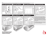
The MVP-50 Glass Panel Engine Monitor Installation consists of four major components: the MVP Display, the
Engine Data Converter (EDC-33T), the Probes, Transducers & Modules, and the Wiring and Extension Cables.
1.1.1 MVP Display:
The MVP Display unit measures 5.55" wide by 5.15" high by 2.4" deep and is designed to be mounted
from behind the aircraft instrument panel. The MVP could be mounted on to a sub-panel which would
then be mounted to the aircraft instrument panel from the front.
The 25-pin D-sub connector on the back of the MVP Display is used to interface the MVP to the EDC-
33T, Power & Ground, GPS, Master Warning and Caution Lights, Audio Panel, etc.
1.1.2 EDC-33T:
The EDC-33T (Engine Data Converter) converts all of the engine and aircraft system signals into serial
data. This data is transmitted to the MVP display via two wires (RS422). If a second EDC is installed, one
of the data lines will be connected to a RS232 channel on the MVP. The EDC measures 4.5" long by 3.5"
wide by 2.2" high and is to be mounted on the cockpit side of the rewall or in an equipment bay. The
EDC reduces the wire bundle to the instrument panel by over 100 wires. There are three 37-pin D-sub
connectors that interface the EDC to the various probes, transducers and modules.
The EDC’s Temperature and Fuel Level inputs can be used to monitor voltage outputs from almost any
transducer. In this way almost any function can be displayed on the MVP.
Up to two EDC’s can be connected to the MVP at a one time. This signicantly increases the total number
of functions that can be displayed on the MVP.
1.1.3 Probes, Transducers and Modules:
The various probes, transducers and modules are mounted in the aircraft at appropriate locations.
Engine Data Converter
(EDC 33T)
To
PWR & GND
Voice Alarm
Ack
On
Off
To PWR & GND
GPS
Audio Panel
Master
Warning
Lights
MVP Display
1515

1.1.4 Wiring & Extension Cables:
The extension cables and wiring provide the connections from the probes, modules or direct connections
to the EDC inputs. Once the wiring and extension cables are installed into the aircraft they become semi-
permanent. Everything else (MVP, EDC, Probes and Modules) can be easily disconnected and removed.
1.2 Operational Overview:
The MVP system measures an engine or aircraft function using a probe or transducer and displays that function on the
MVP screen using the following steps:
A. A probe is mechanically connected to the aircraft and electrically connected to an EDC input. The pre-
wired harness provides most of the electrical connections from the probes to the EDC inputs.
B. The EDC converts the signals from the probes to a digital format (RS422) and sends the data to the MVP.
The EDC has 33 inputs. Many of the inputs can be used for a number of different types of functions.
C. The MVP receives the data from the EDC and the data is processed through the MVP as follows:
1. The data received for each EDC input is assigned a function name and probe. Function names
and probes are set up for each EDC input in System Conguration Screen #1. The probe assigned
provides specic calibration algorithms. Calibration algorithms for any function can be modied in
System Conguration Screen #5. Some functions have special calibration/setup screens (Fuel Tank
Calibration, Tach Time, Engine Hours, Flight Time, Pressure Altitude, Flaps, Trim, etc.).
2. The function is then placed on the Main or System screen of the MVP. System Conguration
Screens #2 or #3 allows the placement location of the function to be selected for either the Main or
System screen.
3. The analog and/or digital display of the function (with redlines, limits, colors, etc) is depicted on
the appropriate screen. Redlines, limits, colors, units, blinking, master warnings and voice les can
be set up for any function in Conguration Screens #4.
Much of the setup for the certified MVP is done at the factory and cannot be changed by the pilot or installer. See the
following Password Protection section for more information.
1.3 Installation Overview:
The installer should start the installation by reviewing the EDC Wiring Work Sheets. There are three work sheets,
one for each of the 37-pin D-Sub connectors on the EDC. The work sheets are packaged with each of the three EDC
wire harnesses. The work sheets provide a list of the functions and probes/transducers included with this kit. The
installation is achieved by performing the following steps:
A. The MVP display is installed. The MVP can be mounted one of two ways; from behind the instrument
panel or on a sub-panel, which is then mounted to the aircraft instrument panel from the front. This method
hides the cutout for the MVP case and makes a clean and good-looking installation. Electronics International
has a MVP sub-panel avaliable (see EI Price List for more information).
B. Probes and Transducers are installed.
C. Control Panels, Pots and Warning Lights are installed.
1616

D. The EDC is installed. This should be installed (with the connectors pointing down) on the inside of the
cockpit or in an instrument bay. For a twin-engine aircraft it can be installed on the backside (not the engine
side) of the firewall. The EDC should NOT be installed in a location where it can be pressure washed.
E. The Wire Harnesses are installed. The wire harnesses for the EDC and MVP are pre-wired and included
in the kit.
F. Field Calibration/Setup steps are performed. Weight & Balance, Fuel Tanks, Horsepower, etc. Functions
are calibrated/setup. Calibration/Setup requires a password. See the following Password Protection section
for more information.
G. System Checkout is performed.
1.4 Password Protection:
The MVP provides a number of screens for the pilot to use during flight, none of which require a password. It also
provides many System Configuration Screens that are used to configure the MVP for a specific aircraft. Some of the
aircraft functions (fuel level, flaps, trim, weight and balance, etc.) MUST be calibrated during installation and some
must be set at the factory or by an OEM.
The MVP provides two levels of passwords for configuring and calibrating the unit.
1.4.1 Level #1 Password (Maintenance):
The Level #1 password is for the installer or maintenance personnel. This password allows the
installer to perform the following:
A. Delete Log Files.
B. Set up the Gear Warning.
C. Adjust the Recovery Factor.
D. Calibrate the Fuel Level for all fuel tanks.
E. Adjust the aircraft’s Weight and Balance data.
F. Set the Fuel Weight, Tach Time and Engine Hours.
G. Set up the Serial Ports.
H. Disable the Bar Graph.
I. Calibrate Pressure Altitude.
J. Calibrate Flap and Trim indications.
For a non-certified MVP, the password is “100.” For a certified unit the password must be obtained from
Electronics International Inc. To qualify for the maintenance password you must be a certified mechanic or
FAA approved shop.
The password protects the MVP from unauthorized access to calibration data. If calibration data is
improperly changed, it could lead to engine or aircraft damage and/or personal injury. Once the MVP is
installed and checked out, the password should be changed (on either the certified or non-certified unit) to a
unique number and it should be protected from unauthorized access.
If the new password is lost or a new shop requires access to calibration data (as allowed by the Maintenance
Password), Electronics International has a method of providing the Maintenance Password to any
authorized shop or personnel.
1717

1.4.2 Level #2 Password (OEM/Experimental):
The Level #2 password is for the Factory, OEM’s, Certied Installers, or experimental users. This
password allows access to all System Conguration Data. For a non-certied MVP, the password is
“100.” For a certied unit the password is only released under a contract or agreement.
The password protects the MVP from unauthorized access to calibration data. If calibration data is
improperly changed, it could lead to engine or aircraft damage and/or personal injury. Once the unit is
installed and checked out, this password should be changed (on either the certied or non-certied unit) to
a unique number and should be protected from unauthorized access.
1818

2.1 Important Information and Initial Checkout:
2.2 Review the "EDC Wiring Work Sheets":
2.3 Verify You Have all the Probes, Modules, Transducers and Cables:
2.4 Install the MVP Display:
2.5 Install the Temperature Probes:
2.6 Install the Pressure Transducers:
2.7 Install the Interface Circuit for Annunciators:
2.8 Install the Interface Circuit for Flap and Trim Pots:
2.9 Install the Interface Circuit for the Gear Position, Unsafe Indicator and Gear Warning:
2.10 Install the CO Guardian CO Detector:
2.11 Install the Shunt:
2.12 Install the Fuel Flow Transducer:
2.13 Install the P-300C Fuel Level Probes:
2.14 Install the P-300M Magnetic Fuel Level Sender:
2.15 Install the Resistive Fuel Level Module (RFLM-4-X):
2.16 Install the Voice Alarm Control Panel:
2.17 Install the Intensity Control Pot (CP-1):
2.18 Install the Master Warning (red) and Caution (yellow) Lights:
2.19 Install the USB-6A:
2.20 Install the FM-SC or AC-1 Converter:
2.21 Install the BC-5xx:
2.22 Installing the NA-1:
2.23 Installing any Additional Modules:
2.24 Installing the EDC-33T:
2.0 HARDWARE INSTALLATION
1919

Blank Page
2020
/